Page 814 of 1954
Stall Speed
Test
CAUTION:
• To prevent transmission damage, do not test stall speed for more than 10 seconds at a time.
• Do not shift the lever while raising the engine speed.
• Be sure to remove the pressure gauge before testing stall speed.
1. Engage the parking brake, and block the front wheels.
2. Connect a tachometer to the engine, and start the engine.
3. Make sure the A/C switch is OFF.
4. After the engine has warmed up to normal operating temperature (the radiator fan comes on), shift into position.
5. Fully press the brake pedal and accelerator for 6 to 8 seconds, and note engine speed.
6. Allow two minutes for cooling, then repeat the test in and positions.
NOTE:
• Stall speed tests should be used for diagnostic purposes only.
• Stall speed should be the same in and positions.
Stall Speed RPM:
Specification: 2,250 rpm
Service Limit: 2,100 - 2,400 rpmProCarManuals.com
Page 1027 of 1954
Front Toe Inspection/Adjustment
NOTE: Use commercially-available computerized four
wheel alignment equipment to measure wheel align-
ment (caster, camber, toe, and/or turning angle).
Follow the equipment manufacturer's instructions.
1. Check the tire pressure.
2. Center the steering wheel spokes.
3. Check the toe with the wheels pointed straight
ahead.
Front toe: 0 ± 2 mm (0±1/16 in)
— If adjustment is required, go on to step 4.
— If no adjustment is required, remove the align-
ment equipment.
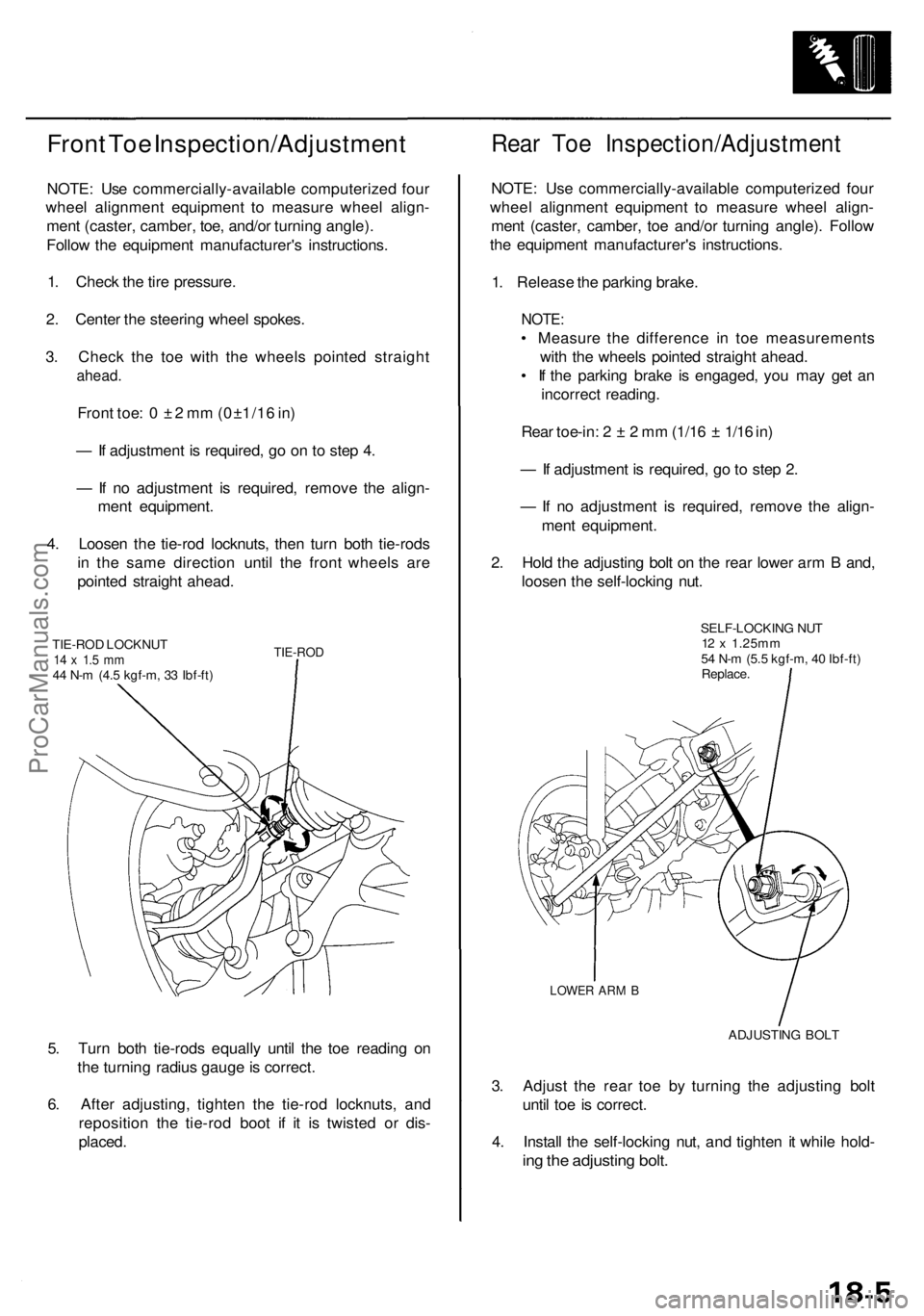
4. Loosen the tie-rod locknuts, then turn both tie-rods
in the same direction until the front wheels are
pointed straight ahead.
TIE-ROD LOCKNUT
14 x 1.5 mm
44 N-m (4.5 kgf-m, 33 Ibf-ft)
TIE-ROD
5. Turn both tie-rods equally until the toe reading on
the turning radius gauge is correct.
6. After adjusting, tighten the tie-rod locknuts, and
reposition the tie-rod boot if it is twisted or dis-
placed.
Rear Toe Inspection/Adjustment
NOTE: Use commercially-available computerized four
wheel alignment equipment to measure wheel align-
ment (caster, camber, toe and/or turning angle). Follow
the equipment manufacturer's instructions.
1. Release the parking brake.
NOTE:
• Measure the difference in toe measurements
with the wheels pointed straight ahead.
• If the parking brake is engaged, you may get an
incorrect reading.
Rear toe-in: 2 ± 2 mm (1/16 ± 1/16 in)
— If adjustment is required, go to step 2.
— If no adjustment is required, remove the align-
ment equipment.
2. Hold the adjusting bolt on the rear lower arm B and,
loosen the self-locking nut.
SELF-LOCKING NUT
12 x 1.25mm
54 N-m (5.5 kgf-m, 40 Ibf-ft)
Replace.
LOWER ARM B
ADJUSTING BOLT
3. Adjust the rear toe by turning the adjusting bolt
until toe is correct.
4. Install the self-locking nut, and tighten it while hold-
ing the adjusting bolt.ProCarManuals.com
Page 1041 of 1954
Rear Suspensio n
Hub Bearin g Uni t Replacemen t
NOTE:
• Us e onl y genuin e Hond a whee l weight s fo r aluminu m wheels . Non-genuin e wheel s weight s ma y corrod e an d damag e
aluminum wheels .
• Befor e installin g th e wheel , clea n th e matin g surface s o f th e brak e dis c an d insid e o f th e wheel .
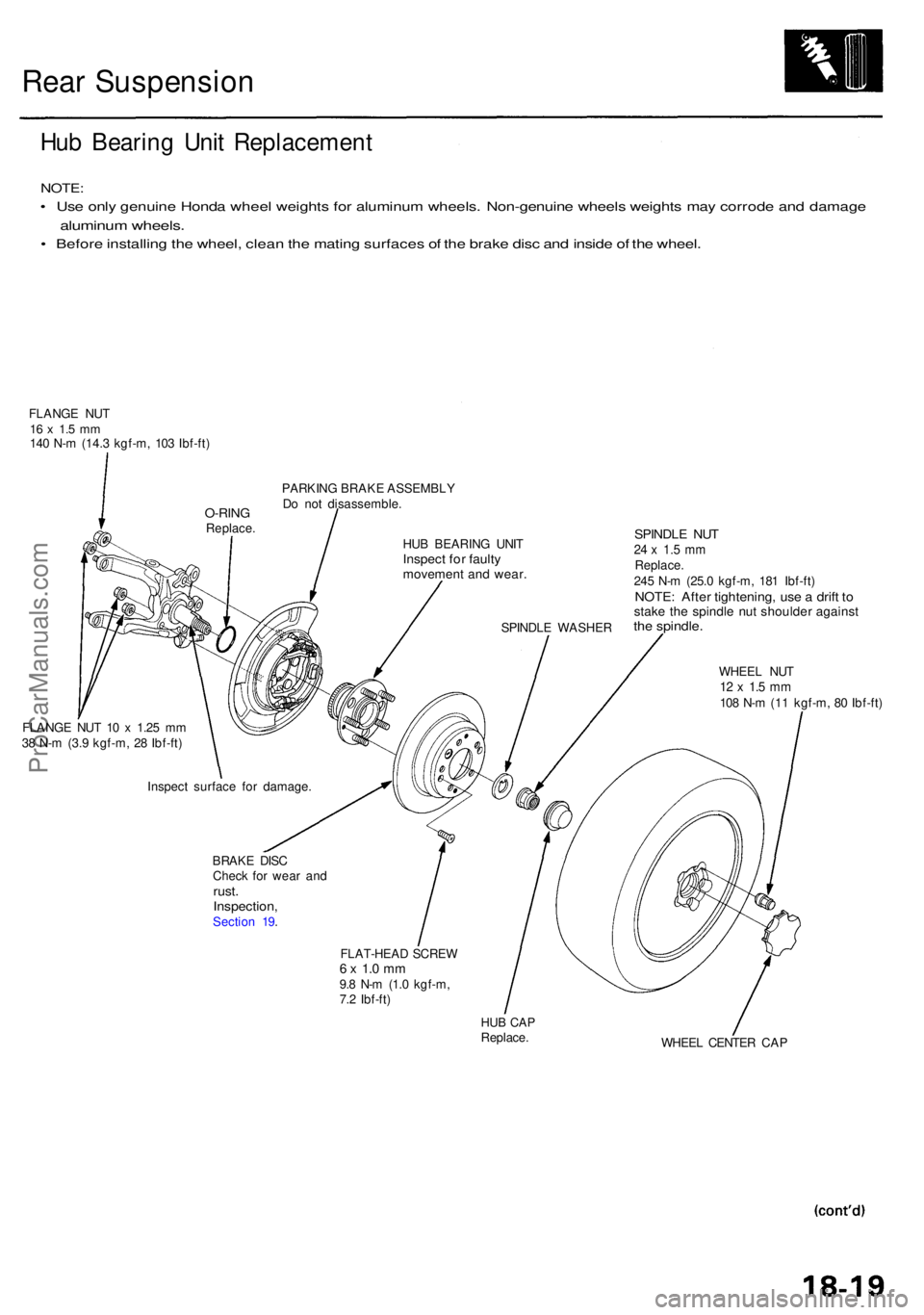
FLANG E NU T16 x 1. 5 m m140 N- m (14. 3 kgf-m , 10 3 Ibf-ft )
PARKING BRAK E ASSEMBL Y
D o no t disassemble .
HU B BEARIN G UNI T
Inspec t fo r fault ymovemen t an d wear .
SPINDL E WASHE R
SPINDLE NU T24 x 1. 5 m mReplace .245 N- m (25. 0 kgf-m , 18 1 Ibf-ft )NOTE : Afte r tightening , us e a drif t t ostak e th e spindl e nu t shoulde r agains tthe spindle .
WHEEL NU T12 x 1. 5 m m108 N- m (1 1 kgf-m , 8 0 Ibf-ft )
FLANG E NU T 1 0 x 1.2 5 m m
3 8 N- m (3. 9 kgf-m , 2 8 Ibf-ft )
BRAKE DIS C
Chec k fo r wea r an d
rust .Inspection ,Section 19 .
FLAT-HEAD SCRE W
6 x 1. 0 m m9.8 N- m (1. 0 kgf-m ,
7. 2 Ibf-ft )
HUB CA PReplace .
WHEEL CENTE R CA P
Inspec
t surfac e fo r damage .
O-RINGReplace .
ProCarManuals.com
Page 1052 of 1954
Inspection an d Adjustmen t
Parking Brak e Peda l
Inspectio n
1 . Pres s th e parkin g brak e peda l wit h 29 4 N (3 0 kgf , 6 6
Ibf ) o f pressur e to full y appl y th e parkin g brake .
Th e parkin g brak e peda l shoul d b e locke d withi n th e
specifie d numbe r o f clicks .
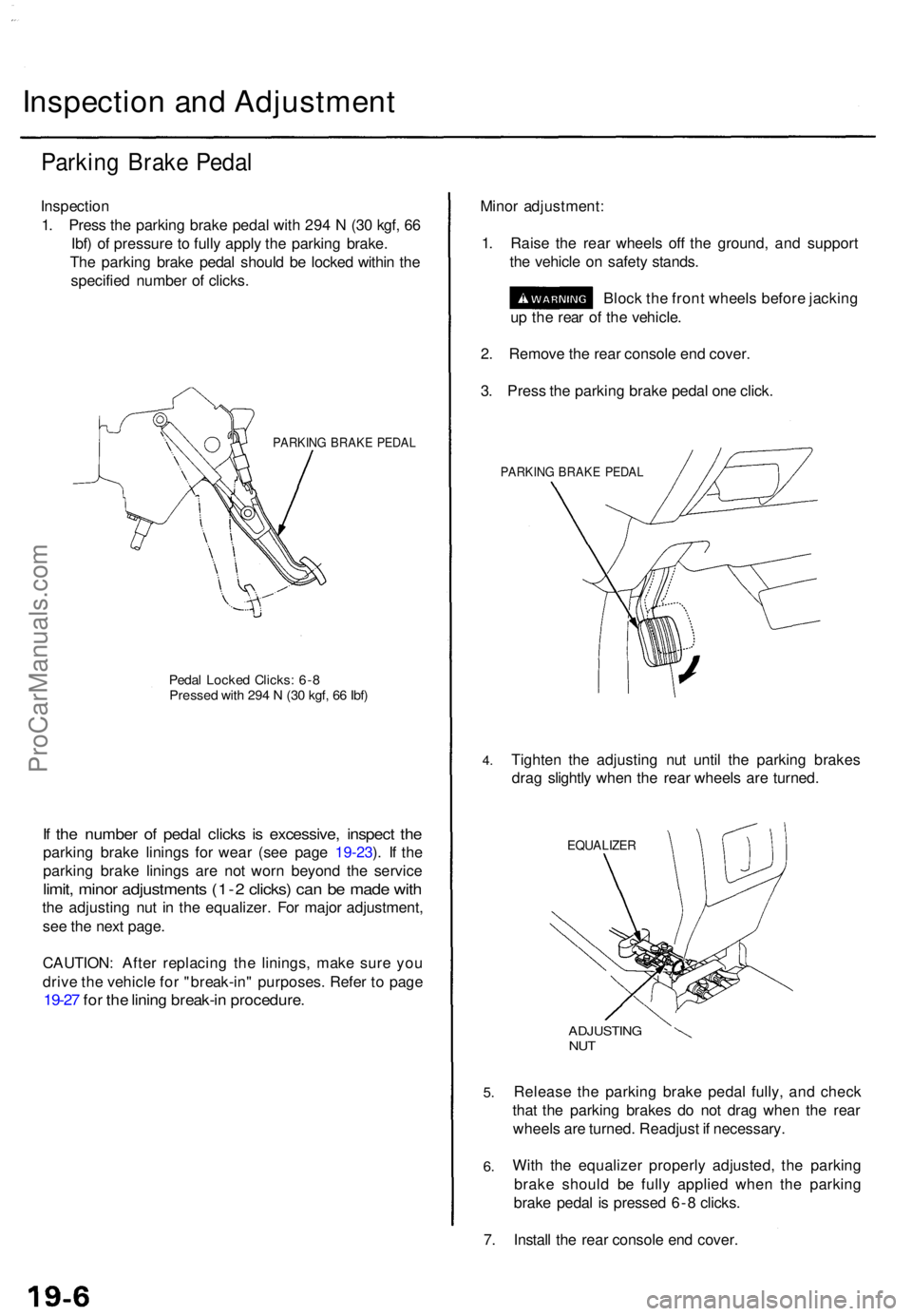
PARKIN G BRAK E PEDA L
Pedal Locke d Clicks : 6- 8Presse d wit h 29 4 N (3 0 kgf , 6 6 Ibf )
If th e numbe r o f peda l click s i s excessive , inspec t th e
parkin g brak e lining s fo r wea r (se e pag e 19-23 ). I f th e
parkin g brak e lining s ar e no t wor n beyon d th e servic e
limit, mino r adjustment s (1- 2 clicks ) ca n b e mad e wit h
the adjustin g nu t i n th e equalizer . Fo r majo r adjustment ,
se e th e nex t page .
CAUTION : Afte r replacin g th e linings , mak e sur e yo u
driv e th e vehicl e fo r "break-in " purposes . Refe r t o pag e
19-27 fo r th e linin g break-i n procedure .
Minor adjustment :
1 . Rais e th e rea r wheel s of f th e ground , an d suppor t
th e vehicl e o n safet y stands .
Bloc k th e fron t wheel s befor e jackin g
u p th e rea r o f th e vehicle .
2 . Remov e th e rea r consol e en d cover .
3 . Pres s th e parkin g brak e peda l on e click .
PARKIN G BRAK E PEDA L
4.Tighte n th e adjustin g nu t unti l th e parkin g brake s
dra g slightl y whe n th e rea r wheel s ar e turned .
EQUALIZE R
5.
6.
ADJUSTIN GNUT
Releas e th e parkin g brak e peda l fully , an d chec k
tha t th e parkin g brake s d o no t dra g whe n th e rea r
wheel s ar e turned . Readjus t i f necessary .
Wit h th e equalize r properl y adjusted , th e parkin g
brak e shoul d b e full y applie d whe n th e parkin g
brak e peda l i s presse d 6- 8 clicks .
7 . Instal l th e rea r consol e en d cover .
ProCarManuals.com
Page 1055 of 1954
Brake Syste m Indicato r
Parking Brak e Switc h Tes t
1 . Remov e th e dashboar d lowe r cove r an d kne e bol -
ste r (se e sectio n 20 ).
2 . Disconnec t th e connecto r fro m th e parkin g brak e
switch .
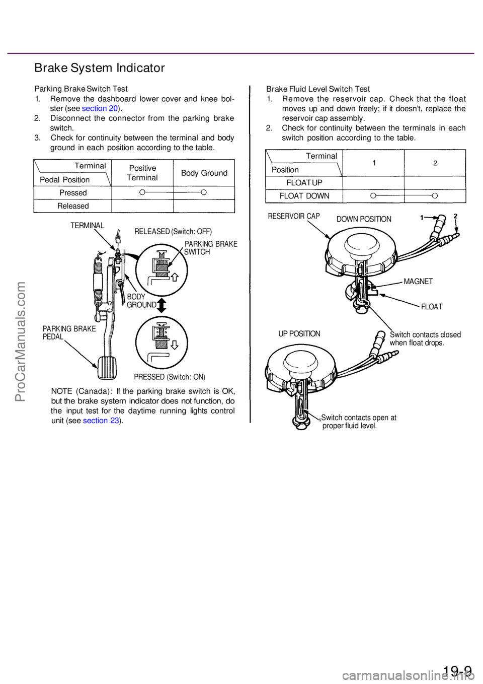
3 . Chec k fo r continuit y betwee n th e termina l an d bod y
groun d i n eac h positio n accordin g t o th e table .
TERMINA LRELEASE D (Switch : OFF )
PARKIN G BRAK ESWITCH
PARKIN G BRAK EPEDAL
PRESSE D (Switch : ON )
NOT E (Canada) : I f th e parkin g brak e switc h i s OK ,
but th e brak e syste m indicato r doe s no t function , d o
th e inpu t tes t fo r th e daytim e runnin g light s contro l
uni t (se e sectio n 23 ). Brak
e Flui d Leve l Switc h Tes t
1 . Remov e th e reservoi r cap . Chec k tha t th e floa t
move s u p an d dow n freely ; i f i t doesn't , replac e th e
reservoi r ca p assembly .
2 . Chec k fo r continuit y betwee n th e terminal s i n eac h
switc h positio n accordin g t o th e table .
RESERVOI R CA PDOW N POSITIO N
FLOAT
Switch contact s close dwhen floa t drops .
sSwitch contact s ope n a tprope r flui d level .
19-9
UP POSITIO N
MAGNET
BODYGROUN D
Positive
Termina lBod
y Groun d
Termina
l
Peda l Positio n
Pressed
Release d
Termina l
Positio n
FLOA T U P
FLOA T DOW N
12
ProCarManuals.com
Page 1072 of 1954
Parking Brak e
Parkin g Brak e Shoe s Replacemen t
Do th e linin g surfac e brake-i n whe n
replacin g th e shoe s wit h ne w lining s and/o r ne w brak e
disc s (drums) .
1 . Remov e th e rea r brak e calipe r an d rea r brak e disc /
drum (se e sectio n 18 ).
2 . Disconnec t an d remov e th e uppe r retur n springs .
'98-01 models :
UPPER RETUR N SPRING S
Chec k fo r weaknes s
an d damage .
'96-97models :
3. Remov e th e tensio n pin s b y pushin g an d turnin g
the retaine r spring .
TENSIO N PIN S
RETAINE R SPRIN G
4. Disconnec t th e ro d spring , an d remov e th e connect -
ing rod .
ROD SPRIN G
Chec k fo r weaknes s
an d damage .
CONNECTIN G ROD
5. Lowe r th e parkin g brak e sho e assembly .
6 . Separat e th e brak e shoe s b y removin g th e lowe r
return sprin g an d adjuste r assembly .
LOWER RETUR N SPRIN G
Chec k fo r weaknes s
an d damage .
ADJUSTE R ASSEMBL YCheck ratche t teet h
fo r wea r an d damage .
ProCarManuals.com
Page 1073 of 1954
7. Remove the brake shoe by disconnecting the park-
ing brake cable from the parking brake lever.
PARKING BRAKE LEVER
PARKING BRAKE CABLE
8. Remove the wave washer, parking brake lever, and
pivot pin from the parking brake shoe by removing
the U-clip.
PARKING BRAKE SHOE
PIVOT PIN
PARKING BRAKE LEVER
U-CLIP WAVE WASHER
Replace.
9. Apply Molykote 44 MA grease to the sliding surface
of the pivot pin, and insert the pin into the parking
brake shoe.
10. Install the parking brake lever and wave washer on
the pivot pin, and secure them with a new U-clip.
NOTE: Pinch the new U-clip securely to prevent the
pivot pin from coming out of the parking brake shoe.
: Apply Molykote 44 MA grease
to sliding surface.
PARKING BRAKE SHOE
PIVOT PIN
PARKING BRAKE LEVER
WAVE WASHER
U-CLIP
Replace.
11. Connect the parking brake cable to the parking brake
lever.
PARKING BRAKE LEVER
PARKING BRAKE CABLEProCarManuals.com
Page 1074 of 1954
Parking Brake
Parking Brake Shoes Replacement (cont'd)
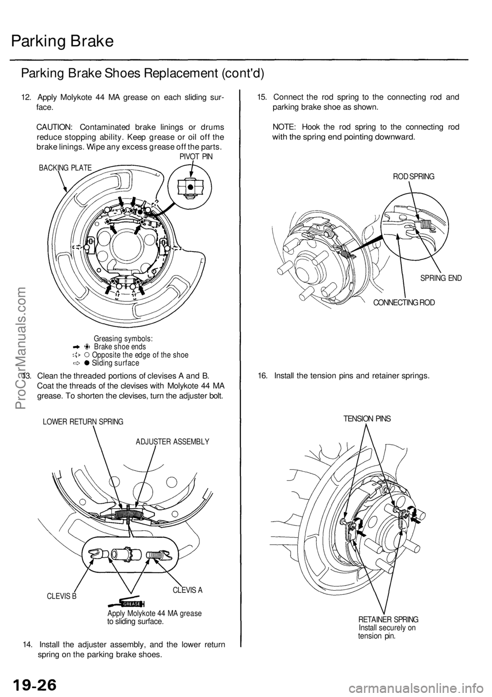
12. Apply Molykote 44 MA grease on each sliding sur-
face.
CAUTION: Contaminated brake linings or drums
reduce stopping ability. Keep grease or oil off the
brake linings. Wipe any excess grease off the parts.
PIVOT PIN
BACKING PLATE
Greasing symbols:
Brake shoe ends
Opposite the edge of the shoe
Sliding surface
13. Clean the threaded portions of clevises A and B.
Coat the threads of the clevises with Molykote 44 MA
grease. To shorten the clevises, turn the adjuster bolt.
LOWER RETURN SPRING
ADJUSTER ASSEMBLY
14. Install the adjuster assembly, and the lower return
spring on the parking brake shoes.
15. Connect the rod spring to the connecting rod and
parking brake shoe as shown.
NOTE: Hook the rod spring to the connecting rod
with the spring end pointing downward.
ROD SPRING
SPRING END
CONNECTING ROD
16. Install the tension pins and retainer springs.
TENSION PINS
RETAINER SPRING
Install securely on
tension pin.
CLEVIS B
CLEVIS A
Apply Molykote 44 MA grease
to sliding surface.ProCarManuals.com