1996 ACURA RL KA9 wiring
[x] Cancel search: wiringPage 213 of 1954
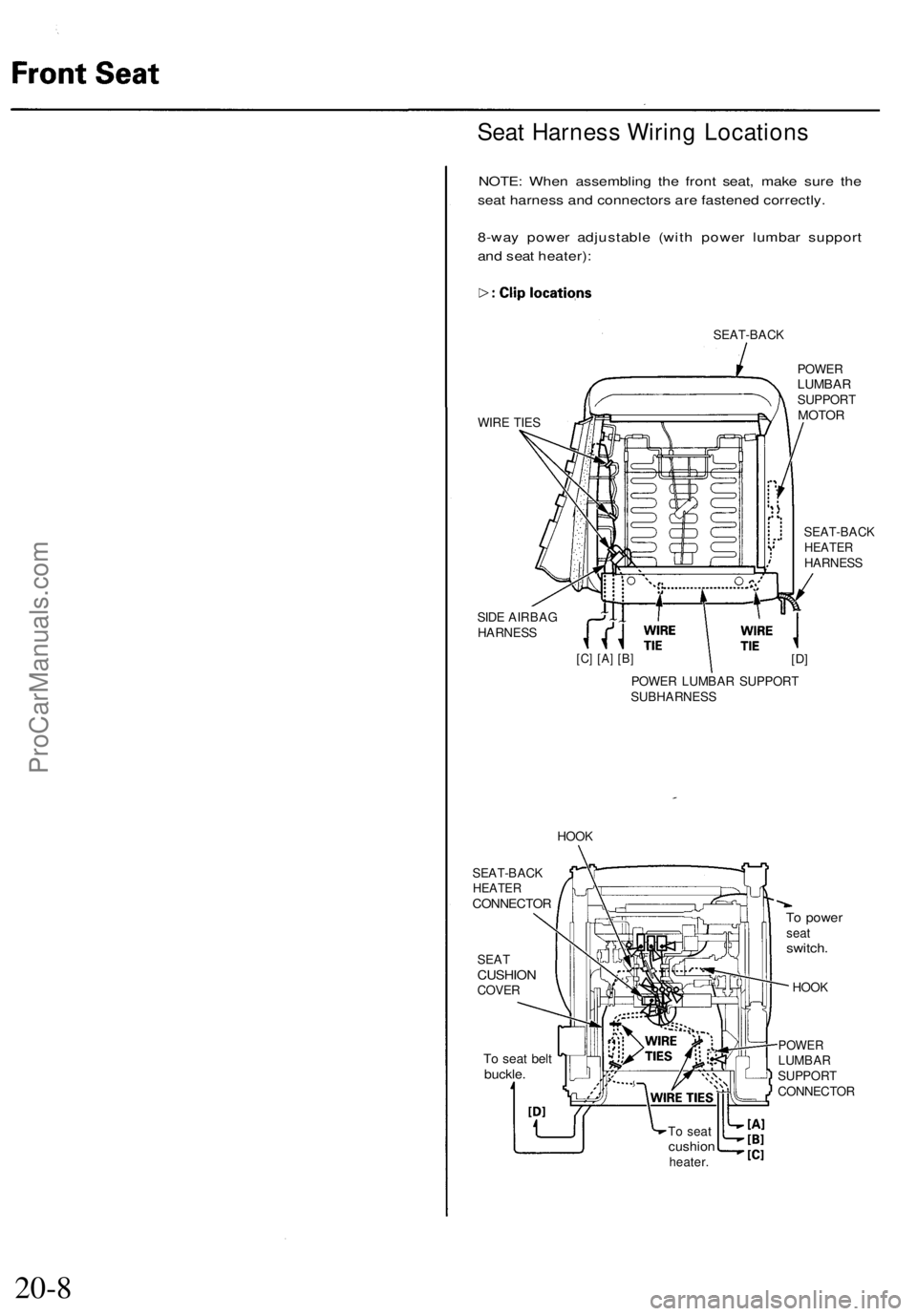
Seat Harness Wiring Locations
NOTE: When assembling the front seat, make sure the
seat harness and connectors are fastened correctly.
8-way power adjustable (with power lumbar support
and seat heater):
SEAT-BACK
WIRE TIES
SIDE AIRBAG
HARNESS
POWER
LUMBAR
SUPPORT
MOTOR
SEAT-BACK
HEATER
HARNESS
[C] [A] [B]
[D]
POWER LUMBAR SUPPORT
SUBHARNESS
HOOK
SEAT
CUSHION
COVER
To seat belt
buckle.
To power
seat
switch.
HOOK
POWER
LUMBAR
SUPPORT
CONNECTOR
To seat
cushion
heater.
20-8
SEAT-BACK
HEATER
CONNECTORProCarManuals.com
Page 275 of 1954

Navigation System
System Diagnosis Mode (cont'd)
GPS Offset Time
This screen is for factory use only. It allows adjustment
of the GPS time. This display updates in real time.
• "GPS Time" is the time as received from the GPS
satellites. It is in Greenwich Mean Time (GMT).
• "System Time" is the internal time used by the navi-
gation unit to calculate your position on the map.
It is also in Greenwich Mean Time (GMT).
• "Display Time" is the time shown on Setup screen 2
"Adjust Time Zone/Clock", and reflects any changes
due to daylight savings time or time adjustments
entered by the customer.
• Date, Hour, Minute, and "Set" buttons should not be
used.
Mic Level
This diagnostic allows you to independently test the
microphone and the TALK and BACK buttons on the
steering wheel (voice control switch). The microphone
and voice control switch are used to activate the voice
control system. The microphone is located near the map
light in the ceiling. It is directional, and works best if the
voice is coming from the drivers seat.
• Press the TALK button on the steering wheel, and in a
normal voice say "testing". The TALK indicator on
the screen should momentarily become green, and
the text "Now Recording..." should appear in yellow.
In addition, the Mic Level indicator should move at
least to the 6th bar. If the Talk indicator on the screen
does not briefly become green, then check the wiring
from the steering wheel talk button to the navigation
unit. If there is no "Mic Level" movement when you
speak, then you should check the wire running from
the microphone to the control unit.
• Press the BACK button on the steering wheel. This
should cause the Cancel indicator on the screen to
momentarily become green. If it does not briefly
change to green, then check the wiring from the
steering wheel BACK button to the navigation unit.ProCarManuals.com
Page 375 of 1954

62. Separate the right engine mount bracket from the
right engine mount, then remove the vacuum hose.
RIGHT ENGINE
MOUNT BRACKET
VACUUM
HOSE
RIGHT ENGINE
MOUNT
63. Separate the left engine mount bracket from the left
engine mount, then remove the vacuum hose.
LEFT ENGINE
MOUNT BRACKET
LEFT ENGINE
MOUNT
VACUUM
HOSE
64. Raise the chain hoist to remove all slack from the
chain.
65. Check that the engine/transmission is completely
free of vacuum hoses, fuel and coolant hoses and
electrical wiring.
66. Slowly raise the engine approximately 150 mm (6 in).
Check once again that all hoses and wires are discon-
nected from the engine/transmission.
67. Raise the engine all the way, and remove it from the
vehicle.ProCarManuals.com
Page 1422 of 1954
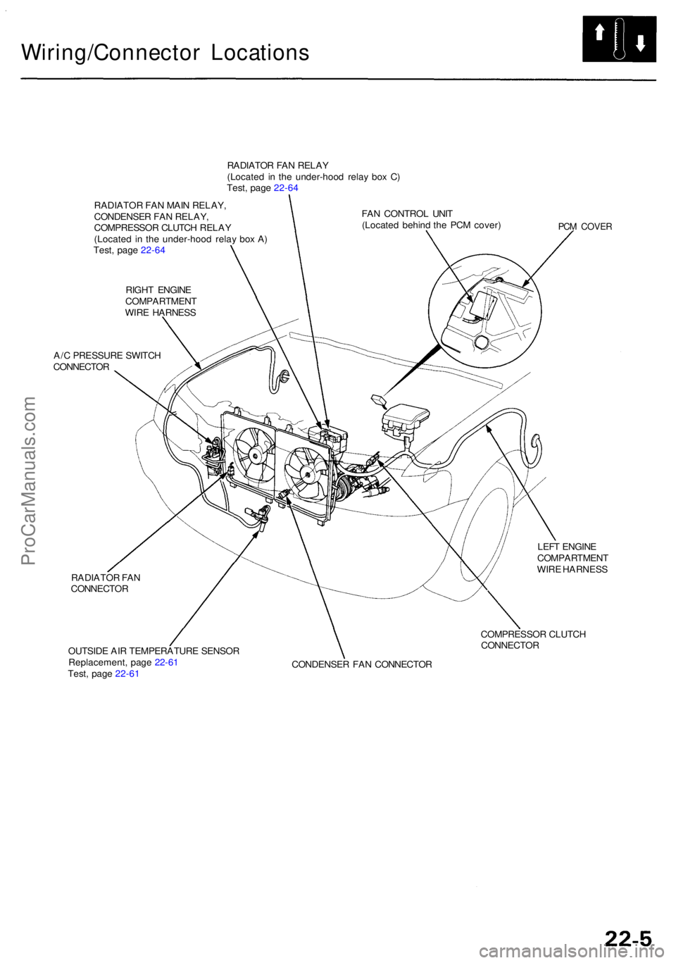
Wiring/Connector Location s
RADIATOR FA N RELA Y
(Locate d i n th e under-hoo d rela y bo x C )
Test , pag e 22-6 4
RADIATO R FA N MAI N RELAY ,
CONDENSE R FA N RELAY ,
COMPRESSO R CLUTC H RELA Y
(Locate d i n th e under-hoo d rela y bo x A )
Test , pag e 22-6 4
RIGH T ENGIN E
COMPARTMEN T
WIR E HARNES S
A/ C PRESSUR E SWITC H
CONNECTO R
RADIATO R FA N
CONNECTO R
OUTSID E AI R TEMPERATUR E SENSO R
Replacement , pag e 22-6 1
Test , pag e 22-6 1 FA
N CONTRO L UNI T
(Locate d behin d th e PC M cover )
PCM COVE R
LEFT ENGIN E
COMPARTMEN T
WIR E HARNES S
COMPRESSO R CLUTC H
CONNECTO R
CONDENSE R FA N CONNECTO R
ProCarManuals.com
Page 1423 of 1954
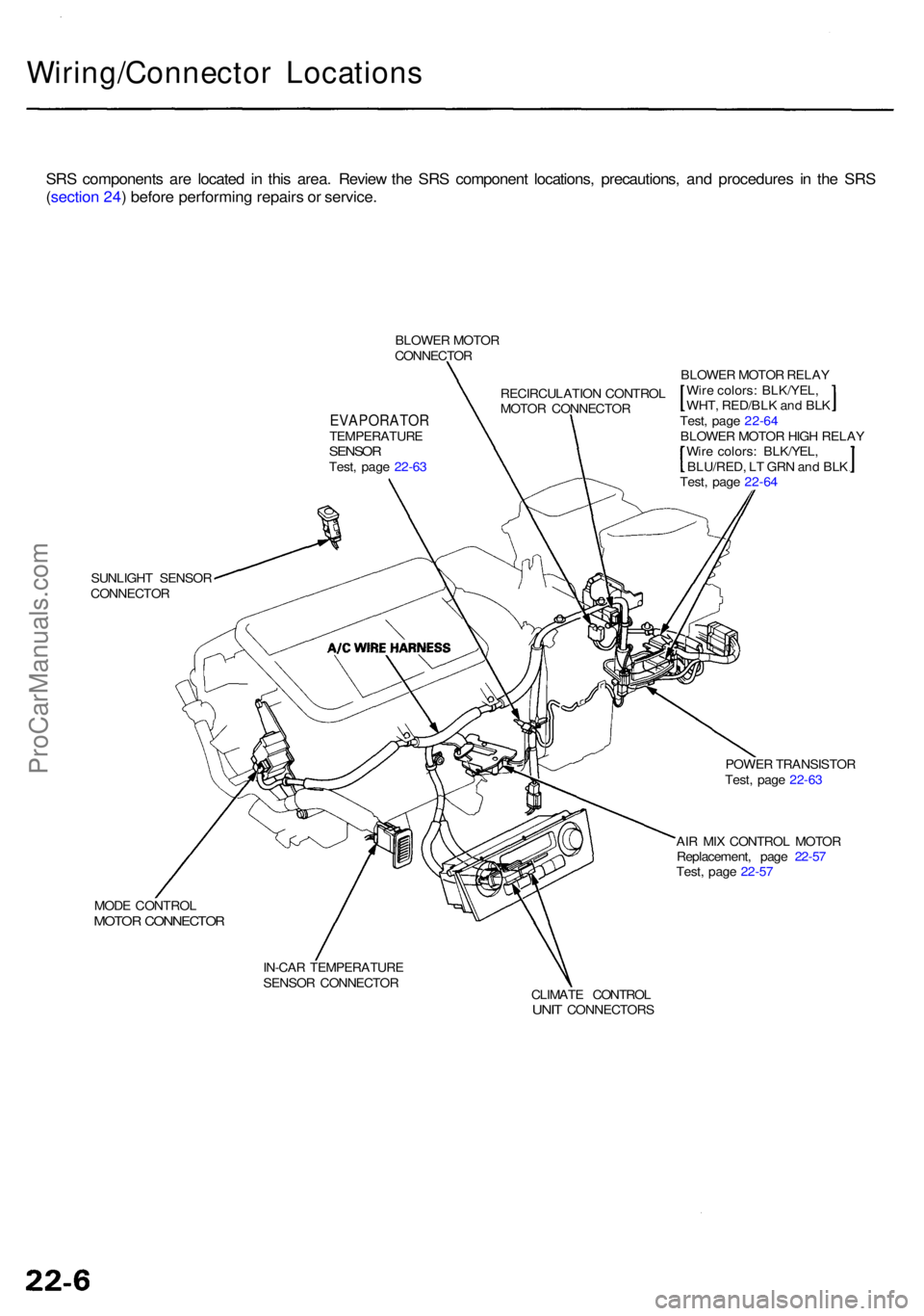
Wiring/Connector Location s
SRS component s ar e locate d i n thi s area . Revie w th e SR S componen t locations , precautions , an d procedure s i n th e SR S
( sectio n 24 ) befor e performin g repair s o r service .
BLOWE R MOTO R
CONNECTO R
EVAPORATO RTEMPERATUR ESENSORTest, pag e 22-6 3 RECIRCULATIO
N CONTRO L
MOTO R CONNECTO R
SUNLIGH T SENSO R
CONNECTO R BLOWE
R MOTO R RELA Y
Wir e colors : BLK/YEL ,
WHT , RED/BL K an d BL K
Test , pag e 22-6 4
BLOWE R MOTO R HIG H RELA Y
Wir e colors : BLK/YEL ,
BLU/RED , L T GR N an d BL K
Test , pag e 22-6 4
POWE R TRANSISTO R
Test , pag e 22-6 3
AI R MI X CONTRO L MOTO R
Replacement , pag e 22-5 7
Test , pag e 22-5 7
MOD E CONTRO L
MOTOR CONNECTO R
IN-CAR TEMPERATUR E
SENSO R CONNECTO R
CLIMATE CONTRO L
UNIT CONNECTOR S
ProCarManuals.com
Page 1507 of 1954
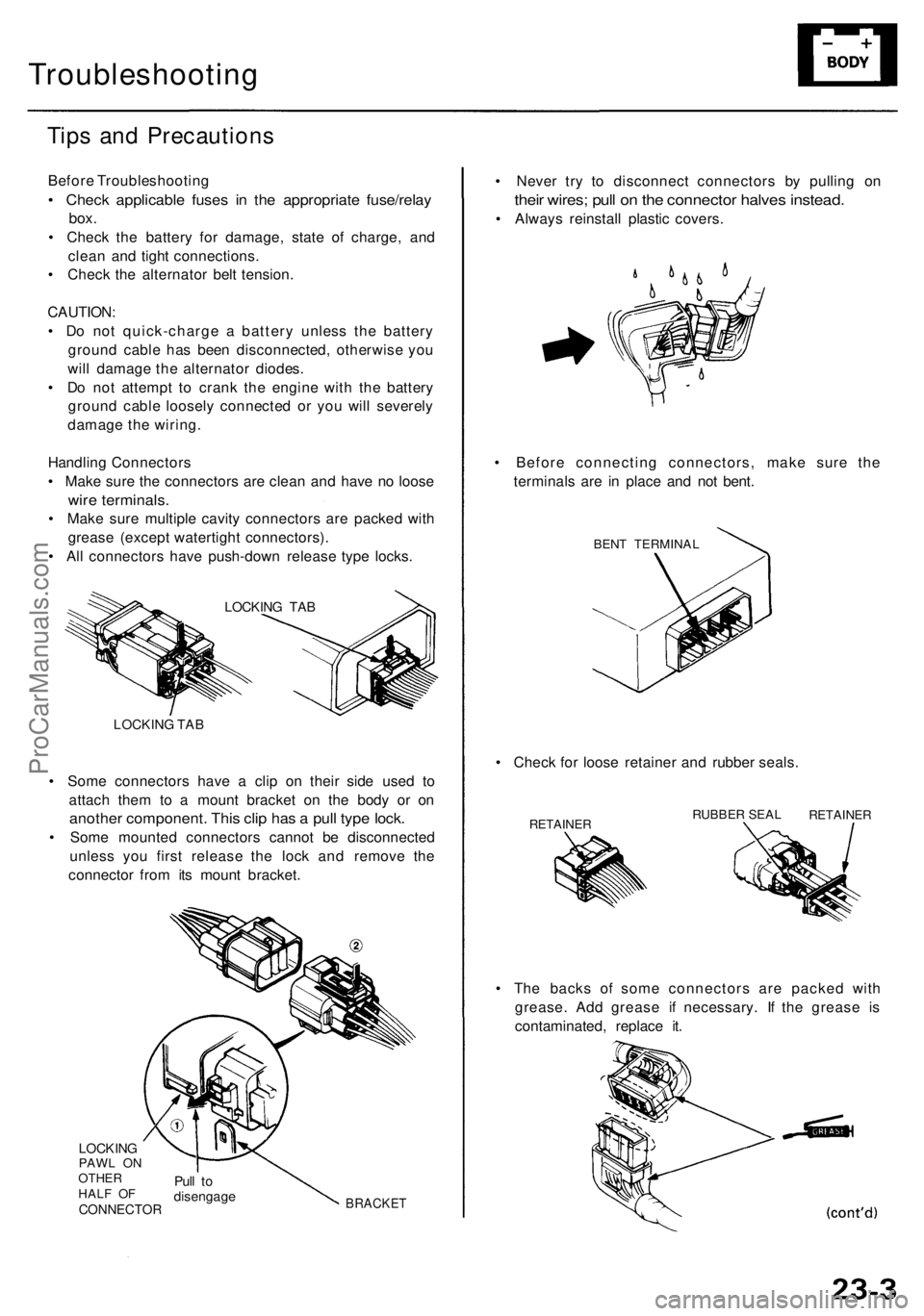
Troubleshooting
Tips an d Precaution s
Before Troubleshootin g
• Chec k applicabl e fuse s i n th e appropriat e fuse/rela y
box.
• Chec k th e batter y fo r damage , stat e o f charge , an d
clea n an d tigh t connections .
• Chec k th e alternato r bel t tension .
CAUTION :
• D o no t quick-charg e a batter y unles s th e batter y
groun d cabl e ha s bee n disconnected , otherwis e yo u
wil l damag e th e alternato r diodes .
• D o no t attemp t t o cran k th e engin e wit h th e batter y
groun d cabl e loosel y connecte d o r yo u wil l severel y
damag e th e wiring .
Handlin g Connector s
• Mak e sur e th e connector s ar e clea n an d hav e n o loos e
wire terminals .
• Mak e sur e multipl e cavit y connector s ar e packe d wit h
greas e (excep t watertigh t connectors) .
• Al l connector s hav e push-dow n releas e typ e locks .
LOCKIN G TA B
LOCKIN G TA B
• Som e connector s hav e a cli p o n thei r sid e use d t o
attac h the m t o a moun t bracke t o n th e bod y o r o n
anothe r component . Thi s cli p ha s a pul l typ e lock .
• Som e mounte d connector s canno t b e disconnecte d
unles s yo u firs t releas e th e loc k an d remov e th e
connecto r fro m it s moun t bracket .
LOCKINGPAWL O N
OTHE R
HAL F O F
CONNECTO R
Pull t odisengag eBRACKET
• Th e back s o f som e connector s ar e packe d wit h
grease . Ad d greas e i f necessary . I f th e greas e i s
contaminated , replac e it .
•
Chec k fo r loos e retaine r an d rubbe r seals .
RETAINE RRUBBER SEA LRETAINE R
• Neve r tr y t o disconnec t connector s b y pullin g o n
thei r wires ; pul l o n th e connecto r halve s instead .
• Alway s reinstal l plasti c covers .
• Befor e connectin g connectors , mak e sur e th e
terminal s ar e i n plac e an d no t bent .
BENT TERMINA L
ProCarManuals.com
Page 1604 of 1954
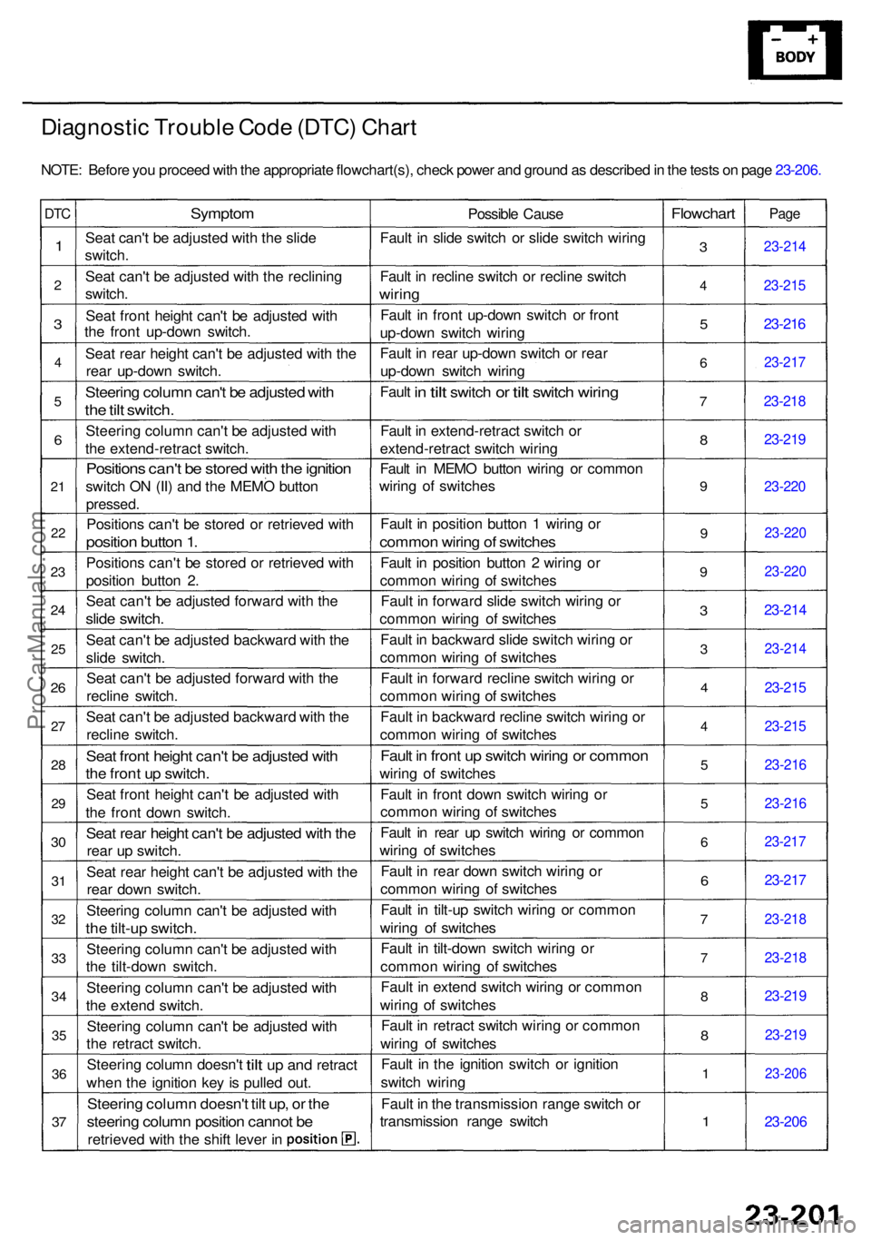
Diagnostic Troubl e Cod e (DTC ) Char t
NOTE : Befor e yo u procee d wit h th e appropriat e flowchart(s) , chec k powe r an d groun d a s describe d in th e test s o n pag e 23-206 .
DTC
1
2
3
4
5
6
21
22
23
2 4
25
26
27
2 8
2 9
30
3 1
3 2
33
3 4
35
36
37
Sympto m
Seat can' t b e adjuste d wit h th e slid e
switch .
Sea t can' t b e adjuste d wit h th e reclinin g
switch .
Sea t fron t heigh t can' t b e adjuste d wit h
th e fron t up-dow n switch .
Sea t rea r heigh t can' t b e adjuste d wit h th e
rea r up-dow n switch .
Steering colum n can' t b e adjuste d wit h
the til t switch .
Steerin g colum n can' t b e adjuste d wit h
th e extend-retrac t switch .
Position s can' t b e store d wit h th e ignitio n
switch O N (II ) an d th e MEM O butto n
pressed .
Positions can' t b e store d o r retrieve d wit h
positio n butto n 1 .
Position s can' t b e store d o r retrieve d wit h
positio n butto n 2 .
Sea t can' t b e adjuste d forwar d wit h th e
slid e switch .
Seat can' t b e adjuste d backwar d wit h th e
slid e switch .
Sea t can' t b e adjuste d forwar d wit h th e
reclin e switch .
Sea t can' t b e adjuste d backwar d wit h th e
reclin e switch .
Seat fron t heigh t can' t b e adjuste d wit h
the fron t u p switch .
Seat fron t heigh t can' t b e adjuste d wit h
th e fron t dow n switch .
Seat rea r heigh t can' t b e adjuste d wit h th e
rea r u p switch .
Sea t rea r heigh t can' t b e adjuste d wit h th e
rea r dow n switch .
Steerin g colum n can' t b e adjuste d wit h
the tilt-u p switch .
Steerin g colum n can' t b e adjuste d wit h
th e tilt-dow n switch .
Steerin g colum n can' t b e adjuste d wit h
th e exten d switch .
Steerin g colum n can' t b e adjuste d wit h
th e retrac t switch .
Steerin g colum n doesn' t
tilt up an d retrac t
whe n th e ignitio n ke y i s pulle d out .
Steerin g colum n doesn' t til t up , o r th e
steerin g colum n positio n canno t b e
retrieve d wit h th e shif t leve r i n Possibl
e Caus e
Faul t i n slid e switc h o r slid e switc h wirin g
Faul t i n reclin e switc h o r reclin e switc h
wiring
Fault i n fron t up-dow n switc h o r fron t
up-dow n switc h wirin g
Faul t i n rea r up-dow n switc h o r rea r
up-dow n switc h wirin g
Faul t
in til t switc h or tilt switc h wiring
Fault i n extend-retrac t switc h o r
extend-retrac t switc h wirin g
Faul t i n MEM O butto n wirin g o r commo n
wirin g o f switche s
Faul t i n positio n butto n 1 wirin g o r
commo n wirin g o f switche s
Fault i n positio n butto n 2 wirin g o r
commo n wirin g o f switche s
Faul t i n forwar d slid e switc h wirin g o r
commo n wirin g o f switche s
Faul t i n backwar d slid e switc h wirin g o r
commo n wirin g o f switche s
Faul t i n forwar d reclin e switc h wirin g o r
commo n wirin g o f switche s
Faul t i n backwar d reclin e switc h wirin g o r
commo n wirin g o f switche s
Fault i n fron t u p switc h wirin g o r commo n
wiring o f switche s
Faul t i n fron t dow n switc h wirin g o r
commo n wirin g o f switche s
Faul t i n rea r u p switc h wirin g o r commo n
wirin g o f switche s
Faul t i n rea r dow n switc h wirin g o r
commo n wirin g o f switche s
Faul t i n tilt-u p switc h wirin g o r commo n
wirin g o f switche s
Faul t i n tilt-dow n switc h wirin g o r
commo n wirin g o f switche s
Faul t i n exten d switc h wirin g o r commo n
wirin g o f switche s
Faul t i n retrac t switc h wirin g o r commo n
wirin g o f switche s
Faul t i n th e ignitio n switc h o r ignitio n
switc h wirin g
Faul t i n th e transmissio n rang e switc h o r
transmissio n rang e switc h
Flowchar t
3
4
5
6
7
8
9
9
9
3
3
4
4
5
5
6
6
7
7
8
8
1
1
Pag e
23-21 4
23-215
23-216
23-21 7
23-218
23-21 9
23-22 0
23-22 0
23-22 0
23-214
23-21 4
23-215
23-21 5
23-21 6
23-216
23-217
23-217
23-21 8
23-218
23-219
23-21 9
23-20 6
23-206
ProCarManuals.com
Page 1790 of 1954
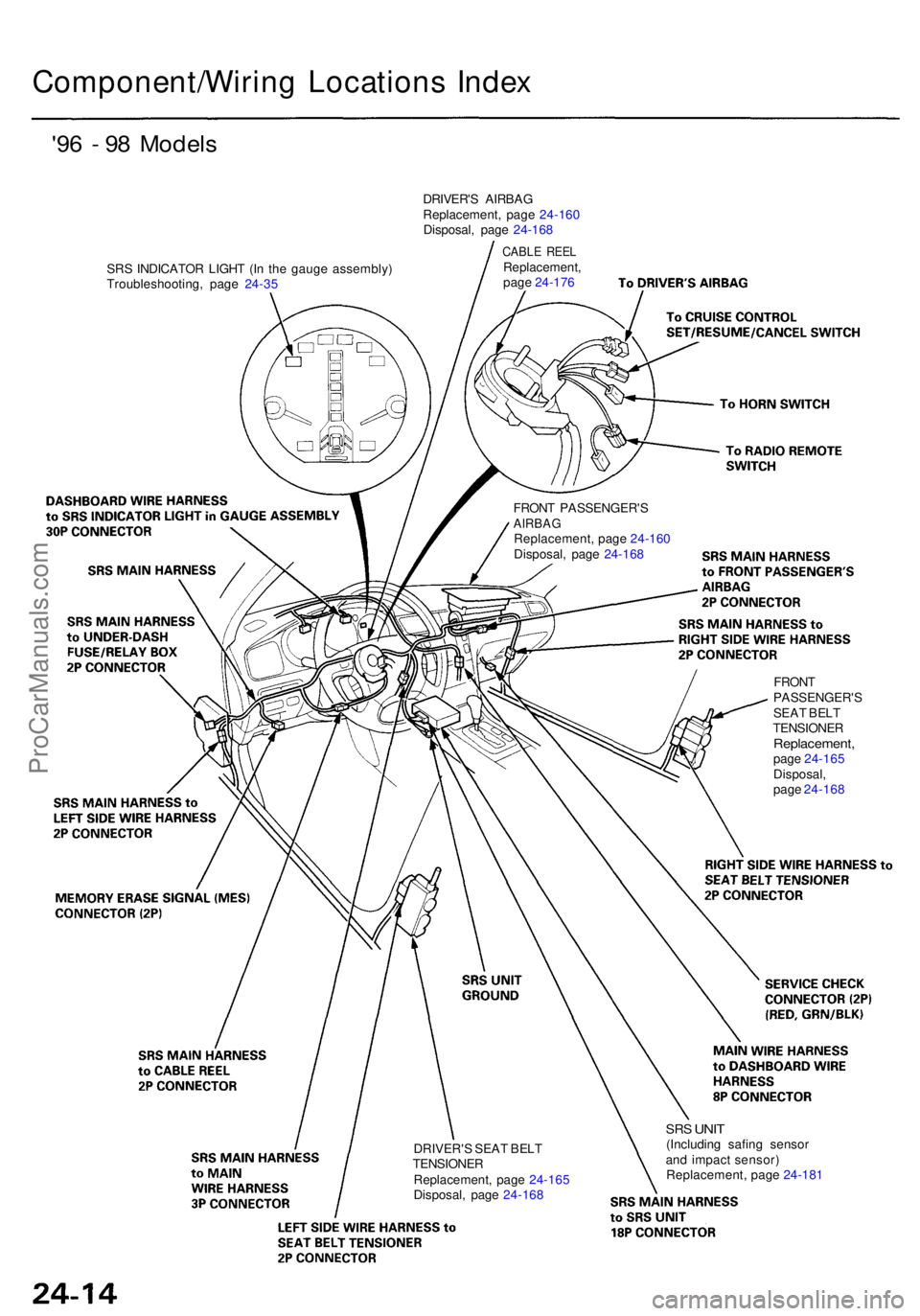
Component/Wiring Location s Inde x
'96 - 9 8 Model s
SRS INDICATO R LIGH T (I n th e gaug e assembly )
Troubleshooting , pag e 24-3 5 DRIVER'
S AIRBA G
Replacement , pag e 24-16 0
Disposal , pag e 24-16 8
CABL E REE LReplacement ,
pag e 24-17 6
FRON T PASSENGER' S
AIRBAGReplacement , pag e 24-16 0
Disposal , pag e 24-16 8
DRIVER' S SEA T BEL T
TENSIONE R
Replacement , pag e 24-16 5
Disposal , pag e 24-16 8
SRS UNI T(Includin g safin g senso r
an d impac t sensor )
Replacement , pag e 24-18 1
FRON
T
PASSENGER' SSEAT BEL T
TENSIONE R
Replacement ,page 24-16 5
Disposal ,
pag e 24-16 8
ProCarManuals.com