Page 50 of 1954

OnStar System ('02 Model USA)
OnStar Control Unit Input Test (cont'd)
Disconnect the connectors from the unit
Cavity Wire Test condition
Test: Desired result
Possible cause if result is not obtained
B17
B22
A32
B6
B3
B2
B9
B18
B32
WHT/YEL
WHT
BLK
ORN
RED/GRN
BLK
Under all conditions
Ignition switch in ACC
(I)
Under all conditions
Under all conditions
Under all conditions
Under all conditions
Check for voltage to ground:
There should be battery voltage.
Check for voltage to ground:
There should be battery voltage.
Check for continuity to ground:
There should be continuity.
Connect to ground:
All horns should sound.
Connect to ground:
The taillights should come on.
Check for continuity to ground:
There should be continuity.
• Blown No. 56 (7.5 A) fuse in the
under-hood fuse/relay box
• An open in the wire
• Blown No. 4 (10 A) fuse in the
under-dash fuse/relay box
• An open in the wire
• Poor ground (G601)
• An open in the wire
• Blown No. 39 (15 A) fuse in the
under-hood fuse/relay box
• Faulty horn relay
• Either horn faulty
• Poor ground (G201)
• An open in the wire
• Blown No. 1 (15 A) fuse in the
under-dash fuse/relay box
• Faulty taillight relay
• Faulty taillight system
• An open in the wire
• An open in the wire
Reconnect the connectors to the unit
Cavity Wire
Test condition
Test: Desired result
Possible cause if result is not obtained
B20
B5
A8
A25
A10
A11
A23
A24
GRN/WHT
GRN/RED
GRY
BRN/YEL
WHT
BLU/RED
BLK
WHT
Front passenger's door
lock key cylinder in neu-
tral position
Front passenger's door
lock key cylinder in
locked position
Front passenger's door
lock key cylinder in neu-
tral position
Front passenger's door
lock key cylinder in
unlocked position
Under all conditions
Under all conditions
OnStar "DOT" button
pushed and human
advisor voice comes
on.
OnStar "DOT" button
pushed and human
advisor voice comes
on.
Under all conditions
Ignition switch in ACC
(I). OnStar "DOT" but-
ton pushed. Speak into
the microphone.
Check for voltage to ground:
There should be battery voltage.
Check for voltage to ground:
There should be less than 1 V.
Check for voltage to ground:
There should be battery voltage.
Check for voltage to ground:
There should be less than 1 V.
Check for continuity to ground:
There should be continuity.
Check for continuity to ground:
There should be continuity.
Check for voltage between the A10
terminal and audio unit C9 or B2
terminal:
There should be 1 V or less.
Check for voltage between the A11
terminal and audio unit C8 or B3
terminal:
There should be 1 V or less.
Check for continuity to ground:
There should be continuity.
Check for voltage to ground:
There should be about 4 V.
• Faulty front passenger's door lock
key cylinder switch
• Poor ground (G401, G402)
• An open in the wire
• Short to ground (if you don't have
5 V when you should)
• An open in the wire
• An open in the wire
• Faulty audio unit
• Faulty speaker
• An open in the wire
• Faulty audio unit
• Faulty speaker
• An open in the wire
• Faulty OnStar buttons and microphone
• An open in the wire
• Faulty OnStar buttons and micro-
phone
• An open in the wireProCarManuals.com
Page 1521 of 1954

8. Afte r reconnectin g th e battery , ente r th e anti-thef t
cod e fo r th e radi o an d th e navigatio n system , the n
ente r th e customer' s radi o statio n presets .
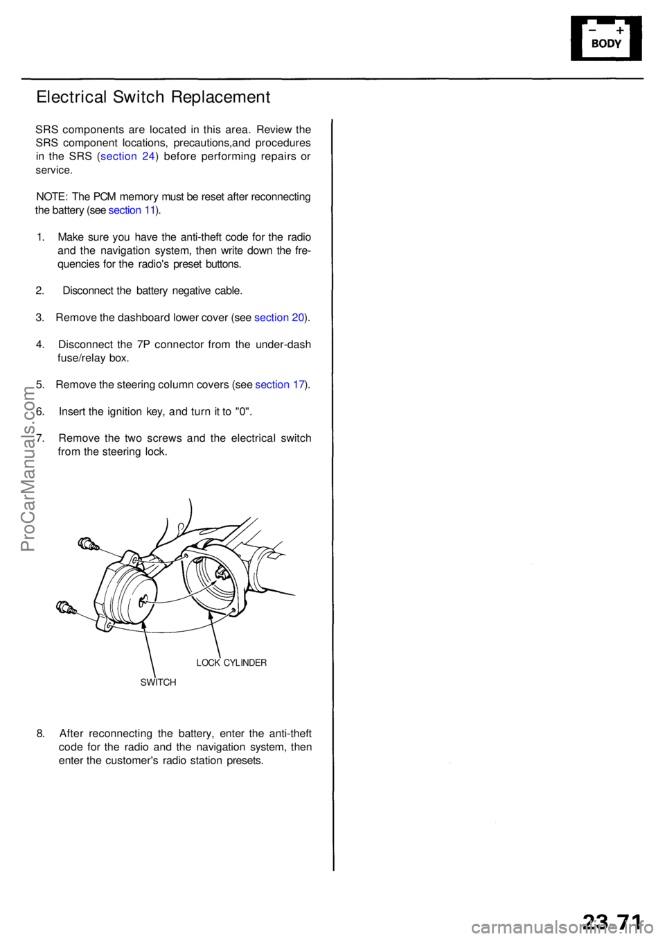
SWITCH
LOCK CYLINDE R
Electrical Switc h Replacemen t
SRS component s ar e locate d i n thi s area . Review the
SR S componen t locations , precautions,an d procedure s
i n th e SR S ( sectio n 24 ) befor e performin g repair s o r
service .
NOTE: Th e PC M memor y mus t b e rese t afte r reconnectin g
th e batter y (se e sectio n 11 ).
1 . Mak e sur e yo u hav e th e anti-thef t cod e fo r th e radi o
an d th e navigatio n system , the n writ e dow n th e fre -
quencie s fo r th e radio' s prese t buttons .
2 . Disconnec t th e batter y negativ e cable .
3 . Remov e th e dashboar d lowe r cove r (se e sectio n 20 ).
4 . Disconnec t th e 7 P connecto r fro m th e under-das h
fuse/rela y box .
5 . Remov e th e steerin g colum n cover s (se e sectio n 17 ).
6 . Inser t th e ignitio n key , an d tur n it t o "0" .
7 . Remov e th e tw o screw s an d th e electrica l switc h
fro m th e steerin g lock .
ProCarManuals.com
Page 1654 of 1954

Confirming the Function
1. Shifting to the sleep mode:
1) Turn the ignition switch OFF.
2) Cancel the key-off operation timer in power window system by opening and closing one of the front doors.
3) Make sure that the trunk is closed, and exterior lights are off.
4) If you do not operate the switches related to the multiplex control units more than one minute after meeting the
above conditions, the system function shifts to the sleep mode.
(All of the switches must be turned OFF except door lock knob switches, ignition key switch, audio switch, and hood
switch.)
2. Confirming the sleep mode:
1) Check for voltage between the wake up line (PNK/BLU wire between driver's and passenger's control unit).
There should be no voltage with the sleep mode OFF.
There should be battery voltage with the sleep mode ON.
2) Check for voltage between each communication line and body ground while shifting to the sleep mode. There
should be no voltage.
3) Check the parasitic draw at the battery while shifting to the sleep mode. The ampere should change from 100 mA to
less than 100 mA.
3. Confirming the wake up mode:
After confirming the sleep mode, turn the related switch (see previous table) ON, and wake up each control unit. If all of
the operations works properly, the wake up mode is OK.
(If any of the control units are faulty and cannot wake up, several parts of the system will not work at the same time.)
Multiplex Control SystemProCarManuals.com