1996 ACURA RL KA9 tires
[x] Cancel search: tiresPage 370 of 1954
Engine Removal/Installatio n
Removal (cont'd )
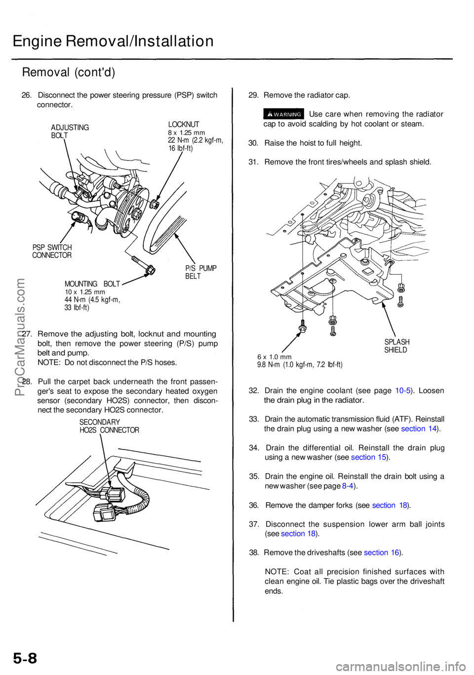
26. Disconnec t th e powe r steerin g pressur e (PSP ) switc h
connector .
ADJUSTIN GBOLT
LOCKNU T8 x 1.2 5 mm22 N- m (2. 2 kgf-m ,
1 6 Ibf-ft )
PS P SWITC H
CONNECTO R
P/S PUM P
BELTMOUNTIN G BOL T10 x 1.2 5 mm44 N- m (4. 5 kgf-m ,
3 3 Ibf-ft )
27. Remov e th e adjustin g bolt , locknu t an d mountin g
bolt, the n remov e th e powe r steerin g (P/S ) pum p
belt an d pump .
NOTE: D o no t disconnec t th e P/ S hoses .
28 . Pul l th e carpe t bac k underneat h th e fron t passen -
ger' s sea t t o expos e th e secondar y heate d oxyge n
senso r (secondar y HO2S ) connector , the n discon -
nec t th e secondar y HO2 S connector . 29
. Remov e th e radiato r cap .
Us e car e whe n removin g th e radiato r
ca p to avoi d scaldin g b y ho t coolan t o r steam .
30 . Rais e th e hois t t o ful l height .
31 . Remov e th e fron t tires/wheel s an d splas h shield .
SPLAS H
SHIEL D
6 x 1. 0 m m9.8 N- m (1. 0 kgf-m , 7. 2 Ibf-ft )
32. Drai n th e engin e coolan t (se e pag e 10-5 ). Loose n
the drai n plu g in th e radiator .
33. Drai n th e automati c transmissio n flui d (ATF) . Reinstal l
th e drai n plu g usin g a ne w washe r (se e sectio n 14 ).
34 . Drai n th e differentia l oil . Reinstal l th e drai n plu g
usin g a ne w washer (see sectio n 15 ).
35 . Drai n th e engin e oil . Reinstal l th e drai n bol t usin g a
ne w washe r (se e pag e 8-4 ).
36 . Remov e th e dampe r fork s (se e sectio n 18 ).
37 . Disconnec t th e suspensio n lowe r ar m bal l joint s
(se e sectio n 18 ).
38 . Remov e th e driveshaft s (se e sectio n 16 ).
NOTE : Coa t al l precisio n finishe d surface s wit h
clea n engin e oil . Ti e plasti c bag s ove r th e driveshaf t
ends.
SECONDAR Y
HO2 S CONNECTO R
ProCarManuals.com
Page 470 of 1954
Oil Pa n
Remova l
Engine remova l i s no t require d i n thi s procedure .
• Mak e sur e jack s an d safet y stand s ar e place d properl y
(se e sectio n 1 ).
• Appl y th e parkin g brak e an d bloc k th e rea r wheel s s o
th e vehicl e wil l no t rol l of f stand s whil e yo u ar e
workin g unde r it .
CAUTION :
• Us e fende r cover s t o avoi d damagin g painte d sur -
faces .
• Unplu g th e wirin g connector s carefull y whil e holdin g
th e connecto r portio n to avoi d damaging .
• Mar k al l wirin g an d hose s t o avoi d misconnection .
Also , b e sur e tha t the y d o no t contac t othe r wirin g
o r hose s o r interfer e wit h othe r parts .
1 . Loose n th e idle r pulle y cente r nu t an d adjustin g bolt ,
the n remov e th e ai r conditionin g (A/C ) compresso r
bel t (se e pag e 5-7 ).
2 . Disconnec t th e powe r steerin g pressur e (PSP )
switc h connector , the n remov e th e powe r steerin g
pum p bel t an d pum p (se e pag e 5-8 ).
3 . Remov e th e lef t an d righ t sid e exhaus t manifol d
covers (se e pag e 9-4 ).
4 . Rais e th e hois t t o ful l height .
5 . Remov e th e fron t tires/wheel s an d splas h shiel d
(se e pag e 5-8 ).
6 . Remov e th e dampe r fork s (se e sectio n 18 ).
7 . Disconnec t th e suspensio n lowe r ar m bal l joint s
with the specia l tool . Refe r t o sectio n 1 8 fo r th e
prope r procedure .
8 . Remov e th e driveshaft s an d intermediat e shaf t (se e
sectio n 16 ).
9 . Drai n th e differentia l oil . Reinstal l th e drai n plu g usin g
a ne w washe r (se e sectio n 15 ).
10 . Drai n th e engin e oil . Reinstal l th e drai n bol t usin g a
ne w washe r (se e pag e 8-4 ).
11 . Disconnec t th e vehicl e spee d senso r (VSS ) connec -
tor , the n remov e th e VSS/powe r steerin g spee d
senso r (se e pag e 5-9 ).
D o no t disconnec t th e flui d hoses .
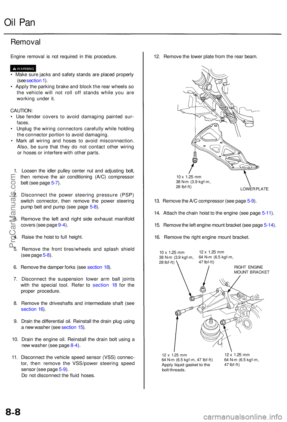
12 x 1.2 5 mm64 N- m (6. 5 kgf-m , 4 7 Ibf-ft )Apply liqui d gaske t t o th ebol t threads .
12 x 1.2 5 mm64 N- m (6. 5 kgf-m ,
4 7 Ibf-ft )
12. Remov e th e lowe r plat e fro m th e rea r beam .
LOWE R PLAT E
10 x 1.2 5 mm38 N- m (3. 9 kgf-m ,
2 8 Ibf-ft )
13. Remov e th e A/ C compresso r (se e pag e 5-9 ).
14 . Attac h th e chai n hois t t o th e engin e (se e pag e 5-11 ).
15 . Remov e th e lef t engin e moun t bracke t (se e pag e 5-14 ).
16 . Remov e th e righ t engin e moun t bracket .
10 x 1.2 5 mm38 N- m (3. 9 kgf-m ,
2 8 Ibf-ft )12 x 1.2 5 mm64 N- m (6. 5 kgf-m ,
4 7 Ibf-ft )
RIGHT ENGIN E
MOUN T BRACKE T
ProCarManuals.com
Page 1026 of 1954
Wheel Alignment
Caster
NOTE: For proper inspection/adjustment of the wheel
alignment, check and adjust the following before check-
ing the alignment:
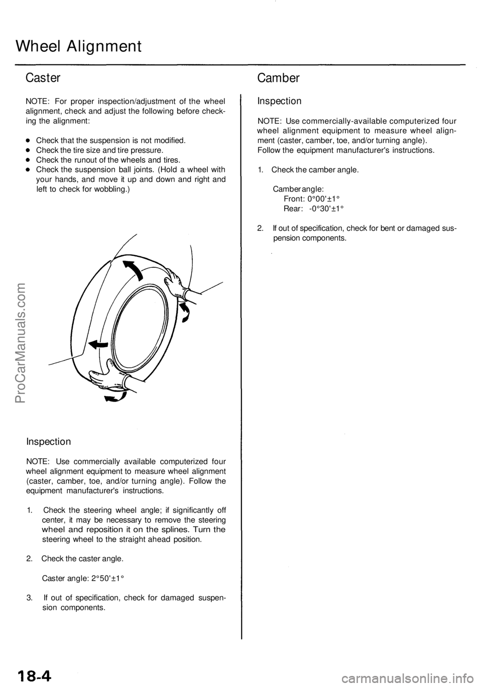
Check that the suspension is not modified.
Check the tire size and tire pressure.
Check the runout of the wheels and tires.
Check the suspension ball joints. (Hold a wheel with
your hands, and move it up and down and right and
left to check for wobbling.)
Inspection
NOTE: Use commercially available computerized four
wheel alignment equipment to measure wheel alignment
(caster, camber, toe, and/or turning angle). Follow the
equipment manufacturer's instructions.
1. Check the steering wheel angle; if significantly off
center, it may be necessary to remove the steering
wheel and reposition it on the splines. Turn the
steering wheel to the straight ahead position.
2. Check the caster angle.
Caster angle: 2°50'±1°
3. If out of specification, check for damaged suspen-
sion components.
Camber
Inspection
NOTE: Use commercially-available computerized four
wheel alignment equipment to measure wheel align-
ment (caster, camber, toe, and/or turning angle).
Follow the equipment manufacturer's instructions.
1. Check the camber angle.
Camber angle:
Front: 0°00'±1°
Rear: -0°30'±1°
2. If out of specification, check for bent or damaged sus-
pension components.ProCarManuals.com
Page 1152 of 1954
Anti-lock Brak e Syste m (ABS )
Features/Constructio n
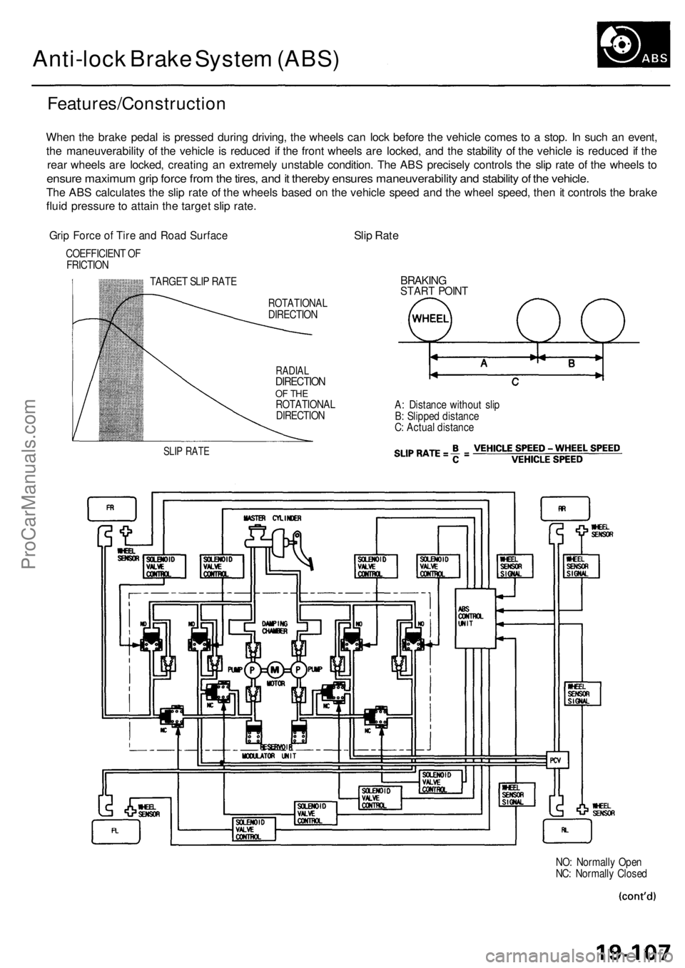
When th e brak e peda l i s presse d durin g driving , th e wheel s ca n loc k befor e th e vehicl e come s t o a stop . I n suc h a n event ,
th e maneuverabilit y o f th e vehicl e i s reduce d i f th e fron t wheel s ar e locked , an d th e stabilit y o f th e vehicl e is reduce d if th e
rea r wheel s ar e locked , creatin g a n extremel y unstabl e condition . Th e AB S precisel y control s th e sli p rat e o f th e wheel s t o
ensur e maximu m gri p forc e fro m th e tires , an d it thereb y ensure s maneuverability and stabilit y o f th e vehicle .
The AB S calculate s th e sli p rat e o f th e wheel s base d o n th e vehicl e spee d an d th e whee l speed , the n it control s th e brak e
flui d pressur e to attai n th e targe t sli p rate .
Grip Forc e o f Tir e an d Roa d Surfac eSlip Rat e
COEFFICIEN T O F
FRICTIO N
TARGET SLI P RAT E
SLIP RAT E
ROTATIONA LDIRECTION
RADIALDIRECTIO NOF TH EROTATIONA L
DIRECTIO N
BRAKINGSTART POIN T
A: Distanc e withou t sli p
B : Slippe d distanc e
C : Actua l distanc e
NO: Normall y Ope n
NC : Normall y Close d
ProCarManuals.com
Page 1192 of 1954
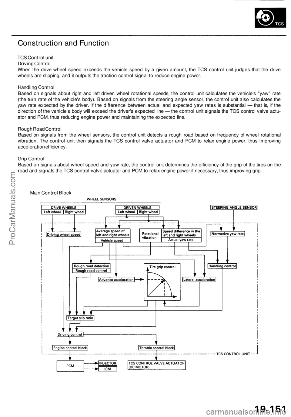
Construction and Function
TCS Control unit
Driving Control
When the drive wheel speed exceeds the vehicle speed by a given amount, the TCS control unit judges that the drive
wheels are slipping, and it outputs the traction control signal to reduce engine power.
Handling Control
Based on signals about right and left driven wheel rotational speeds, the control unit calculates the vehicle's "yaw" rate
(the turn rate of the vehicle's body). Based on signals from the steering angle sensor, the control unit also calculates the
yaw rate expected by the driver. If the difference between actual and expected yaw rates is substantial — that is, if the
direction of the vehicle's body will exceed the driver's expected line — the control unit signals the TCS control valve actu-
ator and PCM, thus reducing engine power and maintaining the expected line.
Rough Road Control
Based on signals from the wheel sensors, the control unit detects a rough road based on frequency of wheel rotational
vibration. The control unit then signals the TCS control valve actuator and PCM to relax engine power, thus improving
acceleration efficiency.
Grip Control
Based on signals about wheel speed and yaw rate, the control unit determines the efficiency of the grip of the tires on the
road and signals the TCS control valve actuator and PCM to relax engine power if necessary, thus improving grip.
Main Control BlockProCarManuals.com
Page 1197 of 1954
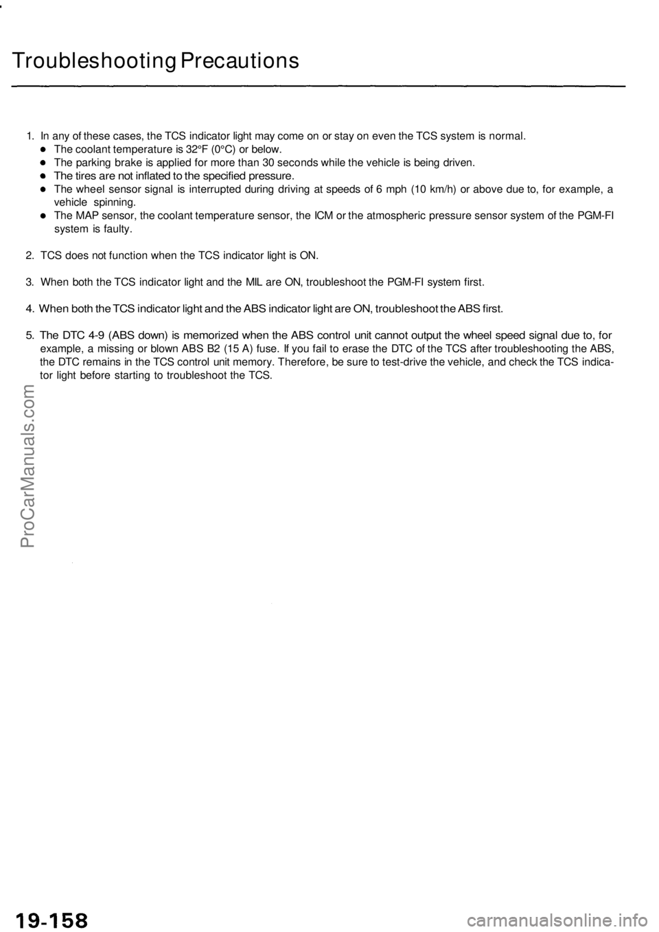
Troubleshooting Precautions
1. In any of these cases, the TCS indicator light may come on or stay on even the TCS system is normal.
The coolant temperature is 32°F (0°C) or below.
The parking brake is applied for more than 30 seconds while the vehicle is being driven.
The tires are not inflated to the specified pressure.
The wheel sensor signal is interrupted during driving at speeds of 6 mph (10 km/h) or above due to, for example, a
vehicle spinning.
The MAP sensor, the coolant temperature sensor, the ICM or the atmospheric pressure sensor system of the PGM-FI
system is faulty.
2. TCS does not function when the TCS indicator light is ON.
3. When both the TCS indicator light and the MIL are ON, troubleshoot the PGM-FI system first.
4. When both the TCS indicator light and the ABS indicator light are ON, troubleshoot the ABS first.
5. The DTC 4-9 (ABS down) is memorized when the ABS control unit cannot output the wheel speed signal due to, for
example, a missing or blown ABS B2 (15 A) fuse. If you fail to erase the DTC of the TCS after troubleshooting the ABS,
the DTC remains in the TCS control unit memory. Therefore, be sure to test-drive the vehicle, and check the TCS indica-
tor light before starting to troubleshoot the TCS.ProCarManuals.com
Page 1258 of 1954
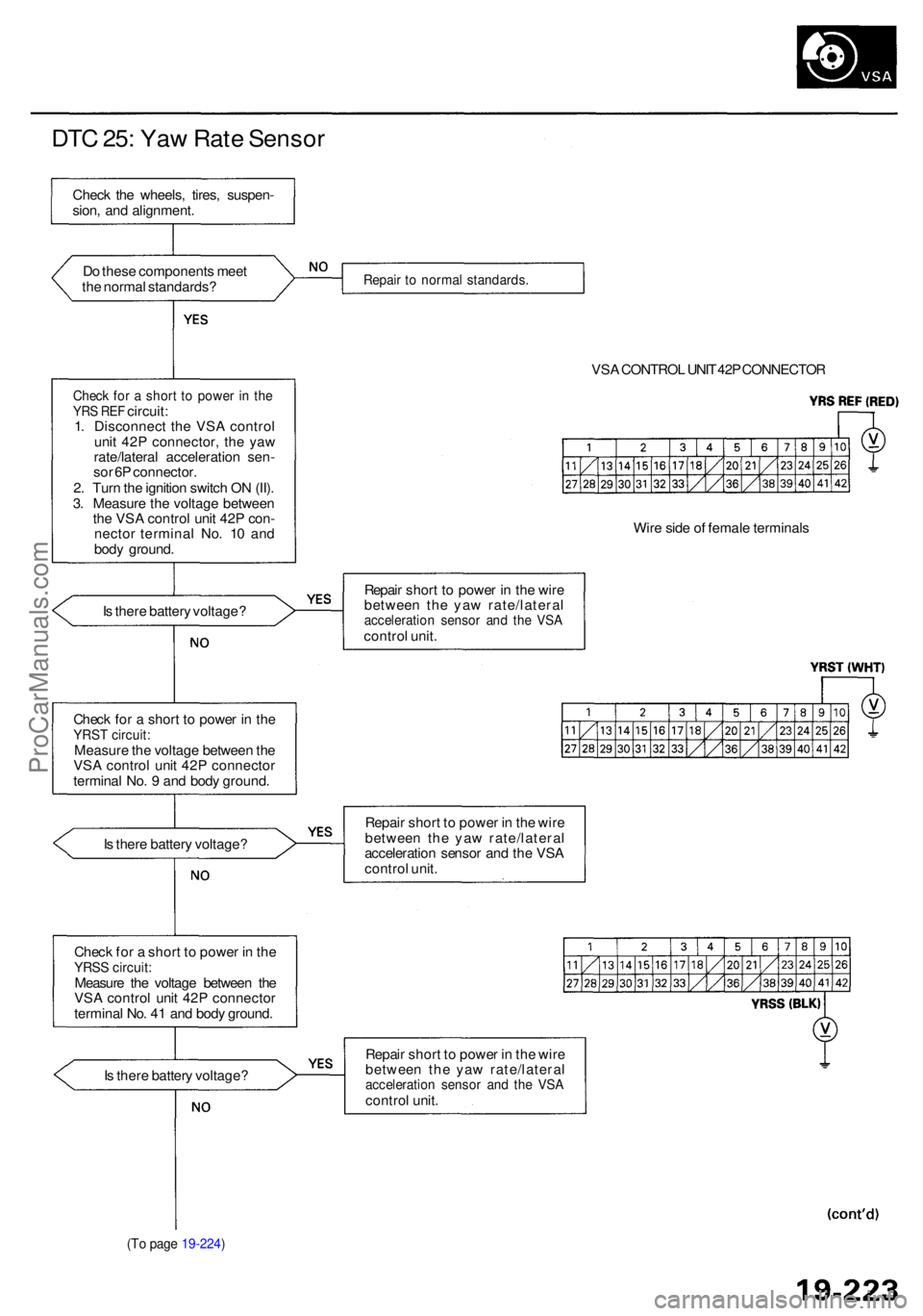
DTC 25 : Ya w Rat e Senso r
Do thes e component s mee t
th e norma l standards ?
Check fo r a shor t t o powe r i n th eYR S RE F circuit :
1 . Disconnec t th e VS A contro l
uni t 42 P connector , th e ya w
rate/latera l acceleratio n sen -
so r 6 P connector .
2 . Tur n th e ignitio n switc h O N (II) .
3 . Measur e th e voltag e betwee n
th e VS A contro l uni t 42 P con -
necto r termina l No . 1 0 an d
bod y ground .
I s ther e batter y voltage ?
Chec k fo r a shor t t o powe r i n th e
YRS T circuit :Measur e th e voltag e betwee n th e
VS A contro l uni t 42 P connecto r
termina l No . 9 an d bod y ground .
I s ther e batter y voltage ?
Chec k fo r a shor t t o powe r i n th e
YRS S circuit :Measur e th e voltag e betwee n th e
VS A contro l uni t 42 P connecto r
termina l No . 4 1 an d bod y ground .
I s ther e batter y voltage ?
(To pag e 19-224 )
Repair t o norma l standards .
VSA CONTRO L UNI T 42 P CONNECTO R
Wir e sid e o f femal e terminal s
Repai r shor t t o powe r i n th e wir e
betwee n th e ya w rate/latera l
acceleration senso r an d th e VS Acontro l unit .
Repai r shor t t o powe r i n th e wir e
betwee n th e ya w rate/latera l
acceleratio n senso r an d th e VS A
contro l unit .
Repai r shor t t o powe r i n th e wir e
betwee n th e ya w rate/latera l
acceleration senso r an d th e VS Acontro l unit .
Chec
k th e wheels , tires , suspen -
sion , an d alignment .
ProCarManuals.com
Page 1261 of 1954
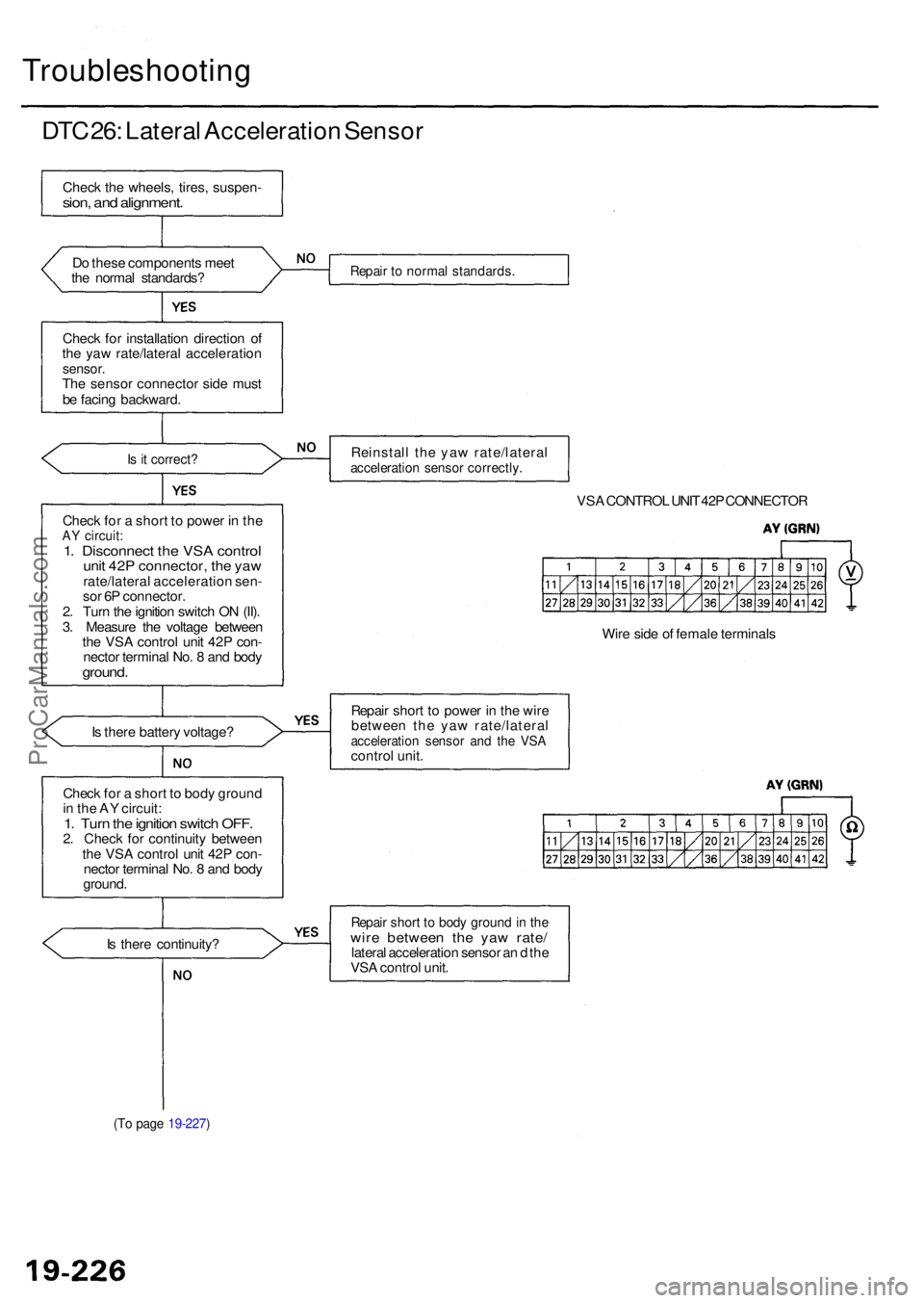
Troubleshooting
DTC 26 : Latera l Acceleratio n Senso r
Check th e wheels , tires , suspen -sion, an d alignment .
Do thes e component s mee t
th e norma l standards ?
Chec k fo r installatio n directio n o f
th e ya w rate/latera l acceleratio n
sensor.The senso r connecto r sid e mus t
b e facin g backward .
Is i t correct ?
Check fo r a shor t t o powe r i n th eAY circuit :1. Disconnec t th e VS A contro lunit 42 P connector , th e ya wrate/latera l acceleratio n sen -
so r 6 P connector .
2 . Tur n th e ignitio n switc h O N (II) .
3 . Measur e th e voltag e betwee n
th e VS A contro l uni t 42 P con -
necto r termina l No . 8 an d bod y
ground .
Is ther e batter y voltage ?
Chec k fo r a shor t t o bod y groun d
i n th e A Y circuit :
1. Tur n th e ignitio n switc h OFF .2. Chec k fo r continuit y betwee n
th e VS A contro l uni t 42 P con -
necto r termina l No . 8 an d bod y
ground .
I s ther e continuity ?
(To pag e 19-227 )
Repair t o norma l standards .
Reinstall th e ya w rate/latera lacceleration senso r correctly .
VSA CONTRO L UNI T 42 P CONNECTO R
Wir e sid e o f femal e terminal s
Repai r shor t t o powe r i n th e wir e
betwee n th e ya w rate/latera l
acceleration senso r an d th e VS Acontro l unit .
Repai r shor t t o bod y groun d in th ewir e betwee n th e ya w rate /lateral acceleratio n senso r a n d th e
VS A contro l unit .
ProCarManuals.com