1996 ACURA RL KA9 bulb
[x] Cancel search: bulbPage 165 of 1954
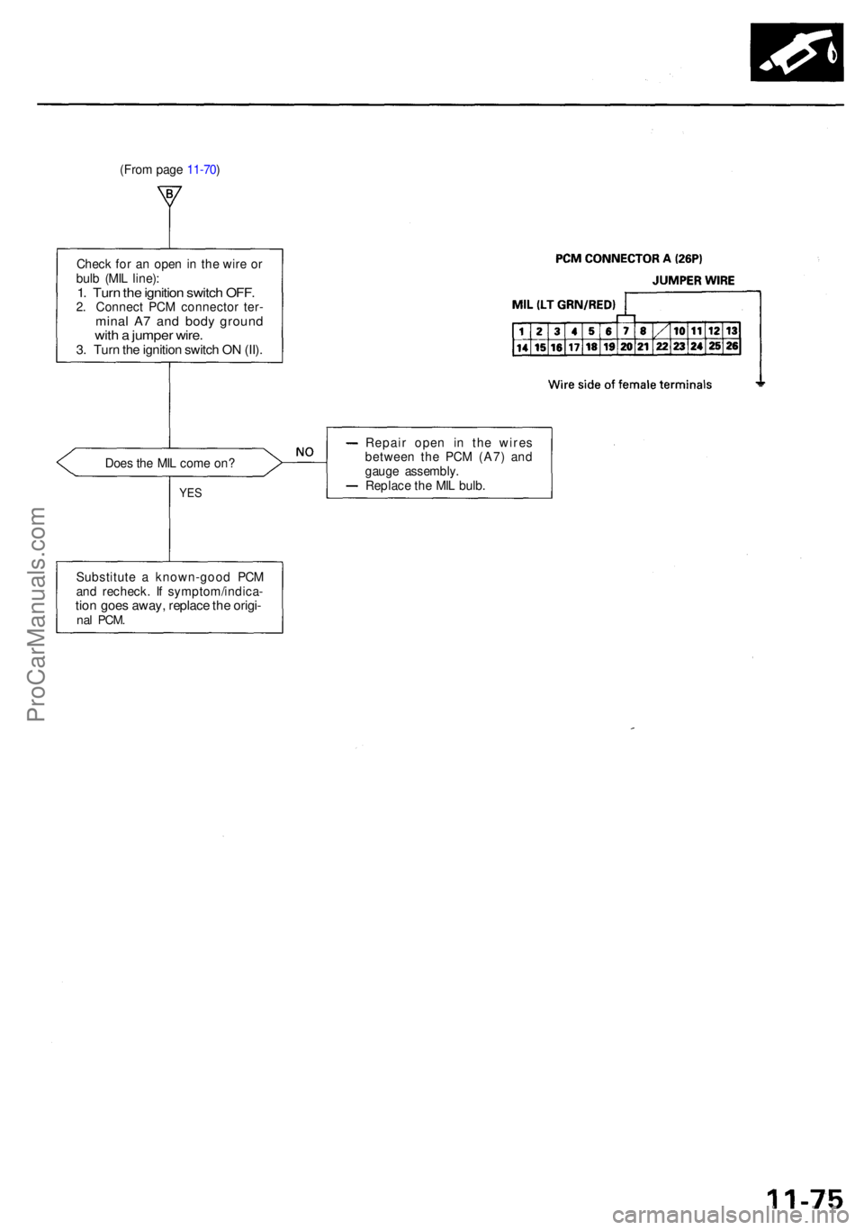
Check fo r a n ope n in th e wir e o r
bul b (MI L line) :
1. Tur n th e ignitio n switc h OFF .2. Connec t PC M connecto r ter -mina l A 7 an d bod y groun dwith a jumpe r wire .3. Tur n th e ignitio n switc h O N (II) .
Doe s th e MI L com e on ?
YES
Repai r ope n i n th e wire s
betwee n th e PC M (A7 ) an d
gaug e assembly .
Replac e th e MI L bulb .
Substitut e a known-goo d PC M
an d recheck . I f symptom/indica -
tion goe s away , replac e th e origi -nal PCM .
(From pag e 11-70 )
ProCarManuals.com
Page 344 of 1954

Troubleshooting
If th e chargin g syste m ligh t doe s no t com e o n o r doe s no t g o off , o r th e batter y i s dea d o r low , tes t th e followin g item s i n
th e orde r liste d below :
1. Batter y (se e sectio n 23 )
2. Chargin g Syste m Ligh t (se e below )
3. Alternator/Regulato r (se e pag e 4-27 )
Chargin g Syste m Ligh t Tes t
Chec k th e No . 2 0 (7. 5 A ) fus e i n
th e under-das h fuse/rela y box .
I s th e fus e OK ?
Chec k fo r a n ope n in th e L circuit :
1 . Disconnec t th e 4 P connecto r
fro m th e alternator .
2 . Groun d th e No . 3 termina l o f
th e 4 P connector .
3 . Tur n th e ignitio n switc h O N (II) .
Doe s th e chargin g syste m
ligh t com e on ?
Disconnec t th e No . 3 termina l
o f th e 4 P connecto r fro m th e
ground .
Doe s th e chargin g syste m
ligh t g o off ?
Chec k fo r a shor t t o bod y groun d
i n th e L circuit :
1 . Tur n th e ignitio n switc h OFF .
2 . Disconnec t th e AB S contro l
uni t (C447 ) an d passenger' s
multiple x contro l uni t (C401) ,
a s applicable .
3. Tur n th e ignitio n switc h O N (II) .
Doe s th e chargin g syste m
ligh t sta y off ?
Chec k fo r shor t i n contro l unit(s) :
1 . Tur n th e ignitio n switc h OFF .
2 . Reconnec t th e AB S contro l
uni t connector .
3 . Tur n th e ignitio n switc h O N
(II) , an d chec k th e chargin g
system light .
Did th e ligh t sta y of f whe n yo u
turne d o n th e ignitio n switc h
afte r connectin g AB S contro l uni t
connector ?
Substitute a known-goo d AB S
contro l unit , an d recheck .
ALTERNATO R4P CONNECTO R
Replace th e fuse .
Chec k fo r a blow n chargin g sys -
te m ligh t bulb . I f th e bul b i s OK ,
repai r th e ope n i n th e WHT/BL U Wir
e sid e o f
femal e terminal s
(T o page 4-26)
Tur n th e ignitio n switc h OFF , an d
repai r th e shor t t o groun d in th e
WHT/BL U wire .
Substitut e a known-goo d pas -
senger' s multiple x contro l unit ,
and recheck .
ProCarManuals.com
Page 356 of 1954

Cruise Control
Control Unit Input Test (cont'd)
Cavity Wire
Test condition
Test: Desired result
Possible cause if result is not obtained
3
13
7
6
14
12
2
5
10
9
11
1
BLK
LT GRN
LT GRN/BLK
LT GRN/RED
PNK
BLU/WHT
GRY
GRN/WHT
BLU/YEL
BRN
BRN/BLK
BRN/WHT
Under all conditions
Ignition switch ON (II) and
main switch ON
Resume button pushed
Cancel button pushed
Set button pushed
Cancel button pushed
Shift lever in , or
Ignition switch ON (II), and
main switch ON; raise the
front of the vehicle, and rotate
one wheel slowly while
holding the other wheel.
Ignition switch ON (II), main
switch ON; brake pedal
pressed, then released
Brake pedal pressed then
released
Ignition switch ON (II)
Under all conditions
Under all conditions
Under all conditions
Check for continuity to ground:
There should be continuity.
Check for voltage to ground:
There should be battery voltage.
Check for voltage to ground:
There should be battery voltage.
When testing terminal No. 7, there
should be no voltage on terminal No. 6.
Check for voltage to ground:
There should be battery voltage.
When testing terminal No. 7, there
should be voltage on terminal No. 6.
Check for voltage to ground:
There should be battery voltage.
When testing terminal No. 6, there
should be no voltage on terminal No. 7.
Check for voltage to ground:
There should be battery voltage.
When testing terminal No. 6, there
should be voltage on terminal No. 7.
Check for continuity to ground:
There should be continuity.
NOTE: There should be no continuity
when the shift lever is in other positions.
Check for voltage between the
BLU/ WHT and BLK terminals:
There should be cycle 0 - 5 V or
battery voltage.
Check for voltage to ground:
There should be 0 V with the pedal
pressed, and battery voltage with
the pedal released.
Check for voltage to ground:
There should be battery voltage with
the pedal pressed, and 0 V with the
pedal released.
Attach to ground:
The cruise light in the gauge assembly
should come on.
Check for resistance to ground:
There should be 80 -120
Check for resistance to ground:
There should be 70 -110
Check for resistance to ground:
There should be 40 - 60
• Poor ground (G401, G402)
• An open in the wire
• Blown No. 20 (20 A) fuse in the
under-dash fuse/relay box
• Faulty main switch
• An open in the wire
• Blown No. 39 (15 A) fuse in the
under-hood fuse/relay box
• Faulty horn relay
• Faulty set/resume/cancel switch
• Faulty cable reel
• An open in the wire
• Short between LT GRN/BLK and
LT GRN/RED wires
• Blown No. 39 (15 A) fuse in the
under-hood fuse/relay box
• Faulty horn relay
• Faulty set/resume/cancel switch
• Faulty cable reel
• An open in the wire
• Blown No. 39 (15 A) fuse in the
under-hood fuse/relay box
• Faulty horn relay
• Faulty set/resume/cancel switch
• Faulty cable reel
• An open in the wire
• Short between LT GRN/BLK and
LT GRN/RED wires
• Blown No. 39 (15 A) fuse in the
under-hood fuse/relay box
• Faulty horn relay
• Faulty set/resume/cancel switch
• Faulty cable reel
• An open in the wire
• Faulty A/T gear position switch
• Poor ground (G401, G402)
• An open in the wire
• Faulty vehicle speed sensor (VSS)
• An open in the wire
• Short to ground
• Blown No. 39 (15 A) fuse in the
under-hood fuse/relay box
• Faulty brake switch
• An open in the wire
• Blown No. 39 (15 A) fuse in the
under-hood fuse/relay box
• Faulty brake switch
• An open in the wire
• Blown bulb
• Faulty gauge circuit
• An open in the wire
• Faulty actuator solenoid
• An open in the wireProCarManuals.com
Page 359 of 1954
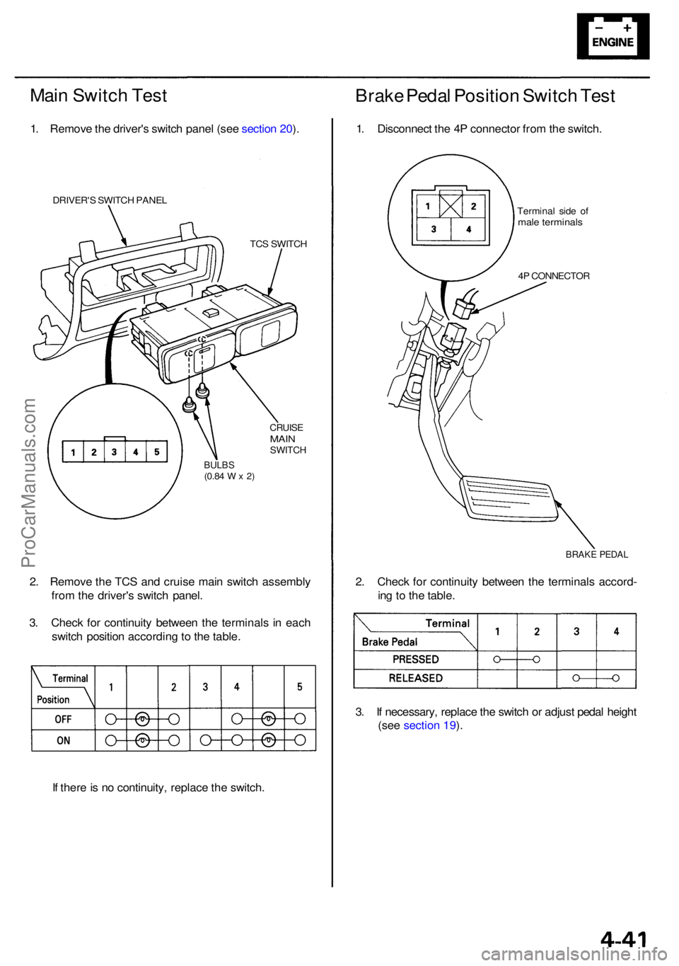
Main Switc h Tes t
1. Remov e th e driver' s switc h pane l (se e sectio n 20 ).
DRIVER' S SWITC H PANE L
TCS SWITC H
CRUISEMAINSWITC H
BULBS(0.84 W x 2)
2. Remov e th e TC S an d cruis e mai n switc h assembl y
fro m th e driver' s switc h panel .
3 . Chec k fo r continuit y betwee n th e terminal s i n eac h
switc h positio n accordin g to th e table .
I f ther e is n o continuity , replac e th e switch .
Brake Peda l Positio n Switc h Tes t
1. Disconnec t th e 4 P connecto r fro m th e switch .
Termina l sid e o fmal e terminal s
4P CONNECTO R
BRAKE PEDA L
2. Chec k fo r continuit y betwee n th e terminal s accord -
in g t o th e table .
3 . I f necessary , replac e th e switc h o r adjus t peda l heigh t
(see section 19 ).
ProCarManuals.com
Page 567 of 1954
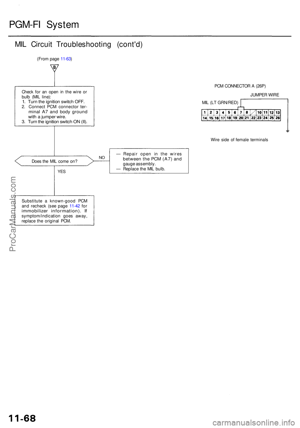
PGM-FI Syste m
MIL Circui t Troubleshootin g (cont'd )
Check fo r a n ope n in th e wir e o r
bul b (MI L line) :
1. Tur n th e ignitio n switc h OFF .2. Connec t PC M connecto r ter -mina l A 7 an d bod y groun dwith a jumpe r wire .3. Tur n th e ignitio n switc h O N (II) .
PCM CONNECTO R A (26P )
Wir e sid e o f femal e terminal s
Doe s th e MI L com e on ?
YES
— Repai r ope n i n th e wire sbetwee n th e PC M (A7 ) an dgaug e assembly .
— Replac e th e MI L bulb .
Substitut e a known-goo d PC M
an d rechec k (se e pag e 11-42 fo r
immobilize r information) . I fsymptom/indicatio n goe s away ,
replac e th e origina l PCM .
NO
MI L (L T GRN/RED )JUMPE
R WIR E
(Fro
m pag e 11-63 )
ProCarManuals.com
Page 649 of 1954

Low Fue l Indicato r Syste m
Indicato r Ligh t Testin g
1 . Chec k th e No . 1 3 METE R (7. 5 A ) fus e i n th e under -
dash fuse/rela y box , METE R (1 5 A ) fus e in th e under -
hood fuse/rela y bo x an d gaug e rela y befor e testing .
2. Par k the vehicl e o n leve l ground .
D o no t smok e whil e workin g o n th e
fue l system . Kee p ope n flam e awa y fro m th e wor k
area . Drai n fue l onl y int o a n approve d container .
• I f th e ligh t come s o n withi n 4 minutes , g o t o ste p
8.
• I f th e ligh t doe s no t com e o n withi n 4 minutes ,
go t o ste p 5 .
5 . Remov e th e rea r sea t cushio n (se e sectio n 20 ).
6 . Remov e th e fue l tan k acces s pane l fro m th e floor ,
an d disconnec t th e 3 P connecto r fro m th e fue l gaug e
sendin g unit .
7. Connec t th e No . 1 an d No . 3 terminal s wit h a jumpe r
wire.
• i f th e ligh t come s on , chec k th e sendin g unit .
• I f th e ligh t doe s no t com e on , chec k for :
— an ope n in th e BLU/RE D wir e betwee n th e fue l
uni t an d fue l gaug e assembly .
— blow n bulb .
— poo r groun d (G652) .
FUEL GAUG E SENDIN G UNI T CONNECTO R IC723 )
should g o of f withi n fou r minutes .
8. Ad d 4of fue l (1. 1 U.S . Gal . 0. 9 Imp . Gal) . Th e ligh t
3. Drai n th e fue l int o a n approve d container . The n
instal l th e drai n bol t wit h a ne w washer .
4.
an d tur n th e ignitio n switc h O N (II) . Th e lo w fue l indi -
cato r ligh t shoul d com e o n withi n 4 minutes .
Add les s tha n 8. 5(2. 2 U.S . Gal . 1. 8 Imp . Gal ) o f fuel ,
ProCarManuals.com
Page 1087 of 1954
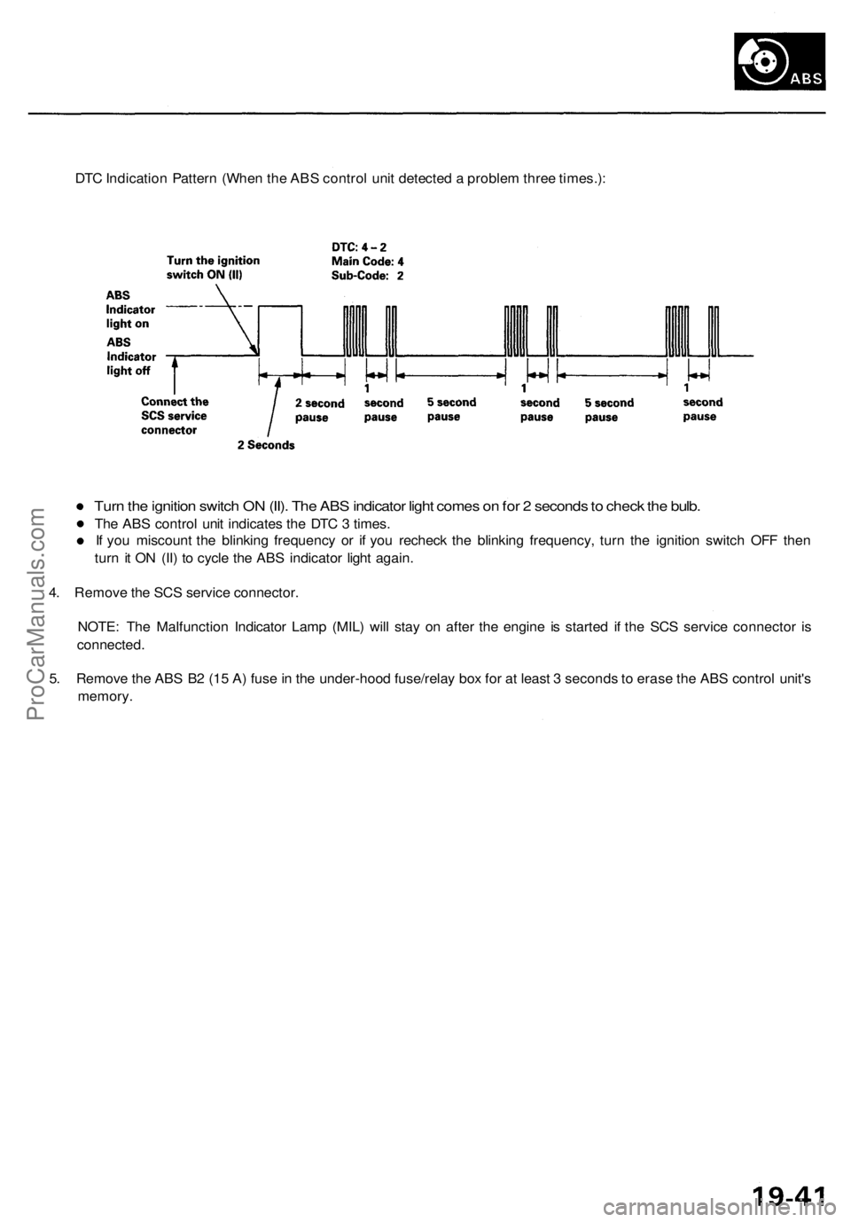
DTC Indication Pattern (When the ABS control unit detected a problem three times.):
Turn the ignition switch ON (II). The ABS indicator light comes on for 2 seconds to check the bulb.
The ABS control unit indicates the DTC 3 times.
If you miscount the blinking frequency or if you recheck the blinking frequency, turn the ignition switch OFF then
turn it ON (II) to cycle the ABS indicator light again.
4. Remove the SCS service connector.
NOTE: The Malfunction Indicator Lamp (MIL) will stay on after the engine is started if the SCS service connector is
connected.
5. Remove the ABS B2 (15 A) fuse in the under-hood fuse/relay box for at least 3 seconds to erase the ABS control unit's
memory.ProCarManuals.com
Page 1089 of 1954
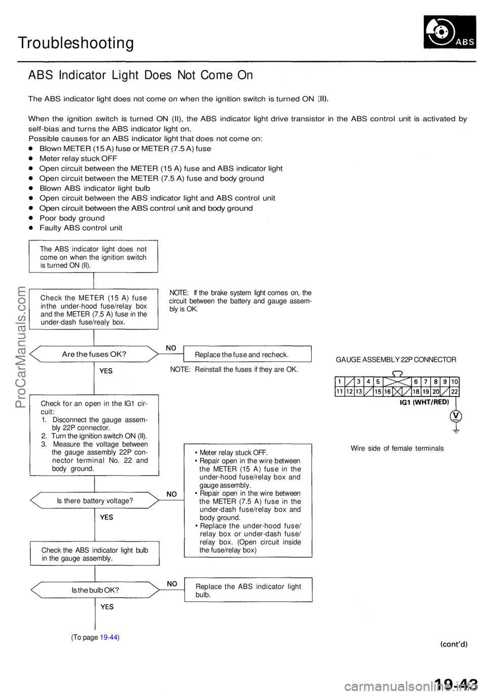
Troubleshooting
ABS Indicato r Ligh t Doe s No t Com e O n
Th e AB S indicato r ligh t doe s no t com e o n whe n th e ignitio n switc h is turne d O N
Whe n th e ignitio n switc h i s turne d O N (II) , th e AB S indicator light driv e transisto r i n th e AB S contro l uni t i s activate d b y
self-bia s an d turn s th e AB S indicato r ligh t on .
Possibl e cause s fo r a n AB S indicato r ligh t tha t doe s no t com e on :
Blow n METE R (1 5 A ) fus e o r METE R (7. 5 A ) fus e
Mete r rela y stuc k OF F
Ope n circui t betwee n th e METE R (1 5 A ) fus e an d AB S indicato r ligh t
Ope n circui t betwee n th e METE R (7. 5 A ) fus e an d bod y groun d
Blow n AB S indicato r ligh t bul b
Ope n circui t betwee n th e AB S indicato r ligh t an d AB S contro l uni t
Ope n circui t betwee n th e AB S contro l uni t an d bod y groun d
Poor bod y groun d
Fault y AB S contro l uni t
The AB S indicato r ligh t doe s no t
com e o n whe n th e ignitio n switc h
i s turne d O N (II) .
Chec k th e METE R (1 5 A ) fus e
i n th e under-hoo d fuse/rela y bo x
an d th e METE R (7. 5 A ) fus e in th e
under-das h fuse/real y box . NOTE
: I f th e brak e syste m ligh t come s on , th e
circui t betwee n th e batter y an d gaug e assem -
bly is OK .
Are th e fuse s OK ?Replac e th e fus e an d recheck .
NOTE : Reinstal l th e fuse s i f the y ar e OK . GAUG
E ASSEMBL Y 22 P CONNECTO R
Chec k fo r a n ope n in th e IG 1 cir -
cuit :
1 . Disconnec t th e gaug e assem -
bl y 22 P connector .
2. Tur n th e ignitio n switc h O N (II) .3. Measur e th e voltag e betwee n
th e gaug e assembl y 22 P con -
necto r termina l No . 2 2 an d
bod y ground .
I s ther e batter y voltage ? Mete
r rela y stuc k OFF .
Repai r ope n in th e wir e betwee n
th e METE R (1 5 A ) fus e i n th e
under-hoo d fuse/rela y bo x an d
gaug e assembly .
Repai r ope n in th e wir e betwee n
th e METE R (7. 5 A ) fus e i n th e
under-das h fuse/rela y bo x an d
bod y ground .
Replac e th e under-hoo d fuse /
rela y bo x o r under-das h fuse /
rela y box . (Ope n circui t insid e
th e fuse/rela y box ) Wir
e sid e o f femal e terminal s
Is th e bul b OK ?Replac e th e AB S indicato r ligh t
bulb .
(T o pag e 19-44 )
Chec
k th e AB S indicato r ligh t bul b
i n th e gaug e assembly .
ProCarManuals.com