1996 ACURA RL KA9 bulb
[x] Cancel search: bulbPage 1106 of 1954
Troubleshooting
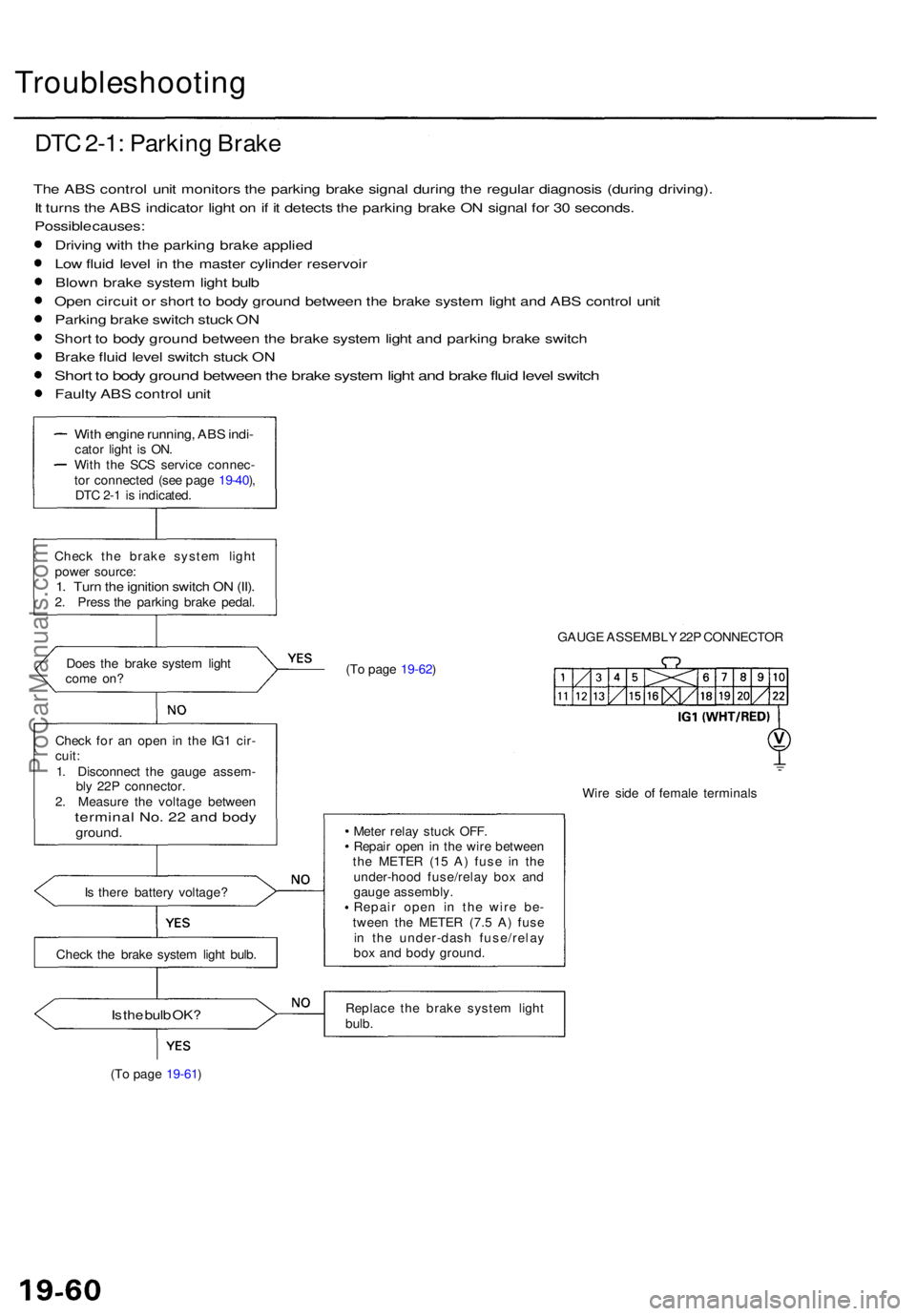
DTC 2-1 : Parkin g Brak e
The AB S contro l uni t monitor s th e parkin g brak e signa l durin g th e regula r diagnosi s (durin g driving) .
I t turn s th e AB S indicato r ligh t o n if i t detect s th e parkin g brak e O N signa l fo r 3 0 seconds .
Possibl e causes :
Drivin g wit h th e parkin g brak e applie d
Lo w flui d leve l i n th e maste r cylinde r reservoi r
Blow n brak e syste m ligh t bul b
Ope n circui t o r shor t t o bod y groun d betwee n th e brak e syste m ligh t an d AB S contro l uni t
Parkin g brak e switc h stuc k O N
Shor t t o bod y groun d betwee n th e brak e syste m ligh t an d parkin g brak e switc h
Brak e flui d leve l switc h stuc k O N
Shor t t o bod y groun d betwee n th e brak e syste m ligh t an d brak e flui d leve l switc h
Faulty AB S contro l uni t
Doe s th e brak e syste m ligh t
com e on ?
Chec k fo r a n ope n in th e IG 1 cir -
cuit :
1 . Disconnec t th e gaug e assem -
bl y 22 P connector .
2 . Measur e th e voltag e betwee n
terminal No . 2 2 an d bod yground .
Is ther e batter y voltage ?
Chec k th e brak e syste m ligh t bulb .
Is th e bul b OK ?
(To pag e 19-61 ) (T
o pag e 19-62 ) GAUG
E ASSEMBL Y 22 P CONNECTO R
Mete r rela y stuc k OFF .
Repai r ope n in th e wir e betwee n
th e METE R (1 5 A ) fus e i n th e
under-hoo d fuse/rela y bo x an d
gaug e assembly .
Repai r ope n i n th e wir e be -
twee n th e METE R (7. 5 A ) fus e
i n th e under-das h fuse/rela y
bo x an d bod y ground .
Replac e th e brak e syste m ligh t
bulb .
With engin e running , AB S indi -cato r ligh t i s ON .
Wit h th e SC S servic e connec -
to r connecte d (se e pag e 19-40 ),
DT C 2- 1 i s indicated .
Chec k th e brak e syste m ligh t
powe r source :
1. Tur n th e ignitio n switc h O N (II) .2. Pres s th e parkin g brak e pedal .
Wire sid e o f femal e terminal s
ProCarManuals.com
Page 1165 of 1954
Troubleshooting
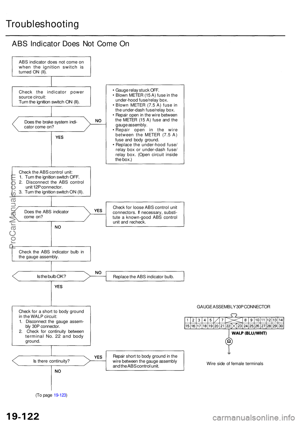
ABS Indicato r Doe s No t Com e O n
AB S indicato r doe s no t com e o nwhe n th e ignitio n switc h i sturne d O N (II) .
Chec k th e indicato r powe r
sourc e circuit :
Turn th e ignitio n switc h O N (II) .
Doe s th e brak e syste m indi -cato r com e on ?
Chec k th e AB S contro l unit :
1. Tur n th e ignitio n switc h OFF .2. Disconnec t th e AB S contro lunit 12 P connector .3. Tur n th e ignitio n switc h O N (II) .
Doe s th e AB S indicato r
com e on ?
Is th e bul b OK ?
Chec k fo r a shor t t o bod y groun d
i n th e WAL P circuit :
1 . Disconnec t th e gaug e assem -
bl y 30 P connector .
2 . Chec k fo r continuit y betwee n
termina l No . 2 2 an d bod yground .
I s ther e continuity ?
(T o pag e 19-123 ) Gaug
e rela y stuc k OFF .
Blow n METE R (1 5 A ) fus e in th e
under-hoo d fuse/rela y box .
Blow n METE R (7. 5 A ) fus e i n
th e under-das h fuse/rela y box .
Repai r ope n in th e wir e betwee n
th e METE R (1 5 A ) fus e an d th e
gaug e assembly .
Repai r ope n i n th e wir e
betwee n th e METE R (7. 5 A )
fus e an d bod y ground .
Replac e th e under-hoo d fuse /
rela y bo x o r under-das h fuse /
rela y box . (Ope n circui t insid e
the box. )
Chec k fo r loos e AB S contro l uni t
connectors . I f necessary , substi -
tut e a known-goo d AB S contro l
uni t an d recheck .
Replac e th e AB S indicato r bulb .
GAUGE ASSEMBL Y 30 P CONNECTO R
Repai r shor t t o bod y groun d in th e
wir e betwee n th e gaug e assembl y
and th e AB S contro l unit .Wire sid e o f femal e terminal s
Chec
k th e AB S indicato r bul b i n
th e gaug e assembly .
ProCarManuals.com
Page 1198 of 1954
Diagnostic Troubl e Cod e (DTC )
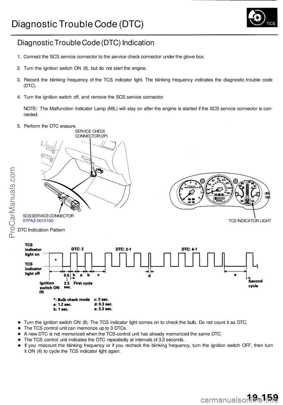
Diagnosti c Troubl e Cod e (DTC ) Indicatio n
1. Connec t th e SC S servic e connecto r t o th e servic e chec k connecto r unde r th e glov e box .
2 . Tur n th e ignitio n switc h O N (II) , bu t d o no t star t th e engine .
3 . Recor d th e blinkin g frequenc y o f th e TC S indicato r light . Th e blinkin g frequenc y indicate s th e diagnosti c troubl e cod e
(DTC) .
4. Tur n th e ignitio n switc h off , an d remov e th e SC S servic e connector .
NOTE : Th e Malfunctio n Indicato r Lam p (MIL ) wil l sta y o n afte r th e engin e is starte d if th e SC S servic e connecto r i s con -
nected .
5 . Perfor m th e DT C erasure .
SERVIC E CHEC KCONNECTO R (2P )
SC S SERVIC E CONNECTO R
07PAZ-001010 0
DTC Indicatio n Patter n
TCS INDICATO R LIGH T
Turn th e ignitio n switc h O N (II) . Th e TC S indicato r ligh t come s o n to chec k th e bulb . D o no t coun t i t a s DTC .
Th e TC S contro l uni t ca n memoriz e u p to 3 DTCs .
A ne w DT C is no t memorize d whe n th e TC S contro l uni t ha s alread y memorize d th e sam e DTC .
Th e TC S contro l uni t indicate s th e DT C repeatedl y a t interval s o f 3. 3 seconds .
I f yo u miscoun t th e blinkin g frequenc y o r i f yo u rechec k th e blinkin g frequency , tur n th e ignitio n switc h OFF , the n tur n
i t O N (II ) t o cycl e th e TC S indicato r ligh t again .
ProCarManuals.com
Page 1201 of 1954
Troubleshooting
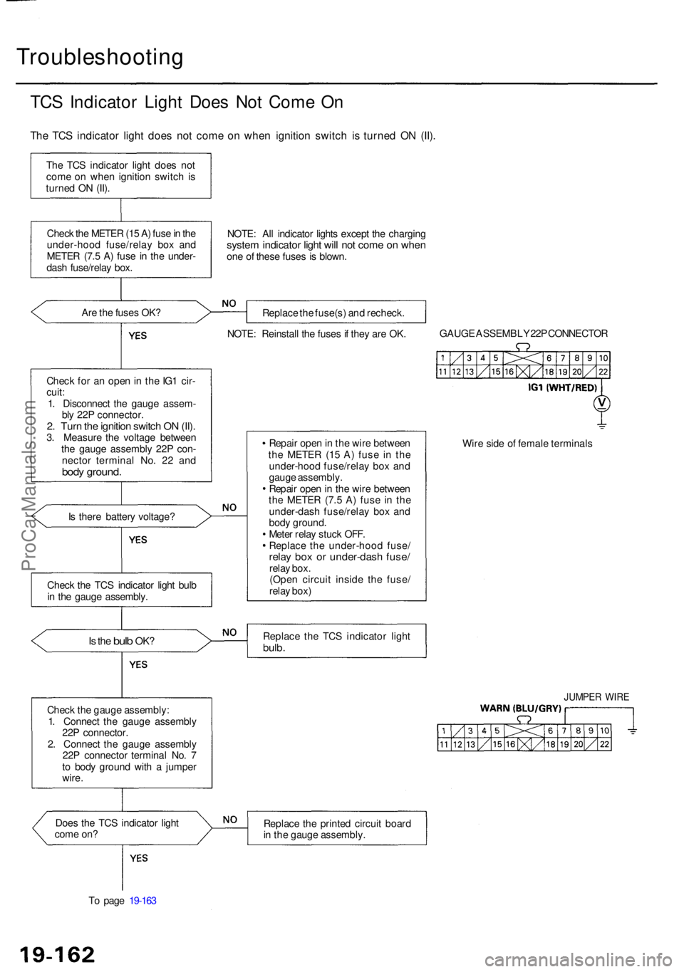
TCS Indicato r Ligh t Doe s No t Com e O n
Th e TC S indicato r ligh t doe s no t com e o n whe n ignitio n switc h i s turne d O N (II) .
The TC S indicato r ligh t doe s no t
com e o n whe n ignitio n switc h is
turne d O N (II) .
Chec k th e METE R (1 5 A ) fus e in th e
under-hoo d fuse/rela y bo x an d
METE R (7. 5 A ) fus e i n th e under -
das h fuse/rela y box .
Ar e th e fuse s OK ?
Chec k fo r a n ope n in th e IG 1 cir -
cuit :
1 . Disconnec t th e gaug e assem -
bl y 22 P connector .
2. Tur n th e ignitio n switc h O N (II) .3. Measur e th e voltag e betwee n
th e gaug e assembl y 22 P con -
necto r termina l No . 2 2 an d
body ground .
Is ther e batter y voltage ?
Is th e bul b OK ?
Chec k th e gaug e assembly :
1 . Connec t th e gaug e assembl y
22 P connector .
2 . Connec t th e gaug e assembl y
22 P connecto r termina l No . 7
t o bod y groun d wit h a jumpe r
wire .
Doe s th e TC S indicato r ligh t
com e on ?
T o pag e 19-16 3 NOTE
: Al l indicato r light s excep t th e chargin g
system indicato r ligh t wil l no t com e o n whe none o f thes e fuse s i s blown .
Replac e th e fuse(s ) an d recheck .
NOTE : Reinstal l th e fuse s if the y ar e OK . GAUG
E ASSEMBL Y 22 P CONNECTO R
Repai r ope n in th e wir e betwee n
th e METE R (1 5 A ) fus e i n th e
under-hoo d fuse/rela y bo x an d
gaug e assembly .
Repai r ope n in th e wir e betwee n
th e METE R (7. 5 A ) fus e i n th e
under-das h fuse/rela y bo x an d
bod y ground .
Mete r rela y stuc k OFF .
Replac e th e under-hoo d fuse /
relay bo x o r under-das h fuse /relay box .
(Ope n circui t insid e th e fuse /
rela y box ) Wir
e sid e o f femal e terminal s
Replac e th e TC S indicato r ligh t
bulb.
JUMPE R WIR E
Replac e th e printe d circui t boar d
i n th e gaug e assembly .
Chec
k th e TC S indicato r ligh t bul b
i n th e gaug e assembly .
ProCarManuals.com
Page 1204 of 1954
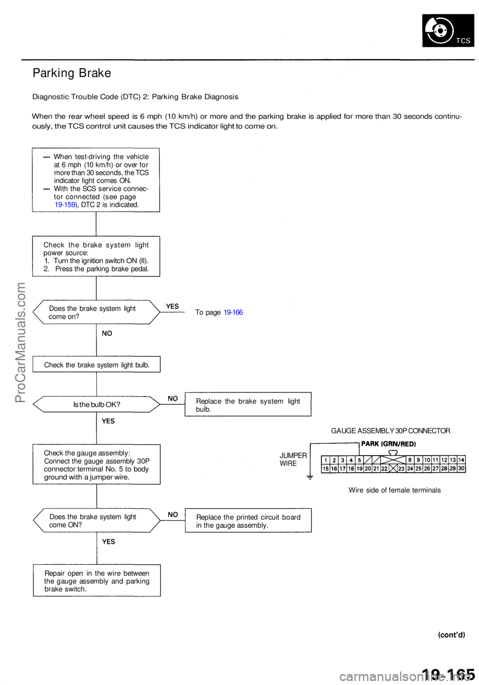
Parking Brak e
Diagnosti c Troubl e Cod e (DTC ) 2 : Parkin g Brak e Diagnosi s
When th e rea r whee l spee d i s 6 mp h (1 0 km/h ) o r mor e an d th e parkin g brak e is applie d fo r mor e tha n 3 0 second s continu -
ously, th e TC S contro l uni t cause s th e TC S indicato r ligh t t o com e on .
Doe s th e brak e syste m ligh t
com e on ? T
o pag e 19-16 6
Is th e bul b OK ?Replac e th e brak e syste m ligh t
bulb .
GAUGE ASSEMBL Y 30 P CONNECTO R
Chec k th e gaug e assembly :
Connec t th e gaug e assembl y 30 P
connecto r termina l No . 5 to bod ygroun d wit h a jumpe r wire .
Wire sid e o f femal e terminal s
Doe s th e brak e syste m ligh t
com e ON ? Replac
e th e printe d circui t boar d
i n th e gaug e assembly .
Repai r ope n i n th e wir e betwee n
th e gaug e assembl y an d parkin g
brak e switch . JUMPE
R
WIRE
Chec k th e brak e syste m ligh t bulb .
Whe
n test-drivin g th e vehicl e
a t 6 mp h (1 0 km/h ) o r ove r fo r
mor e tha n 3 0 seconds , th e TC S
indicato r ligh t come s ON .
Wit h th e SC S servic e connec -
to r connecte d (se e page
19-159 ), DT C 2 is indicated .
Chec k th e brak e syste m ligh t
powe r source :
1. Tur n th e ignitio n switc h O N (II) .2. Pres s th e parkin g brak e pedal .
ProCarManuals.com
Page 1246 of 1954
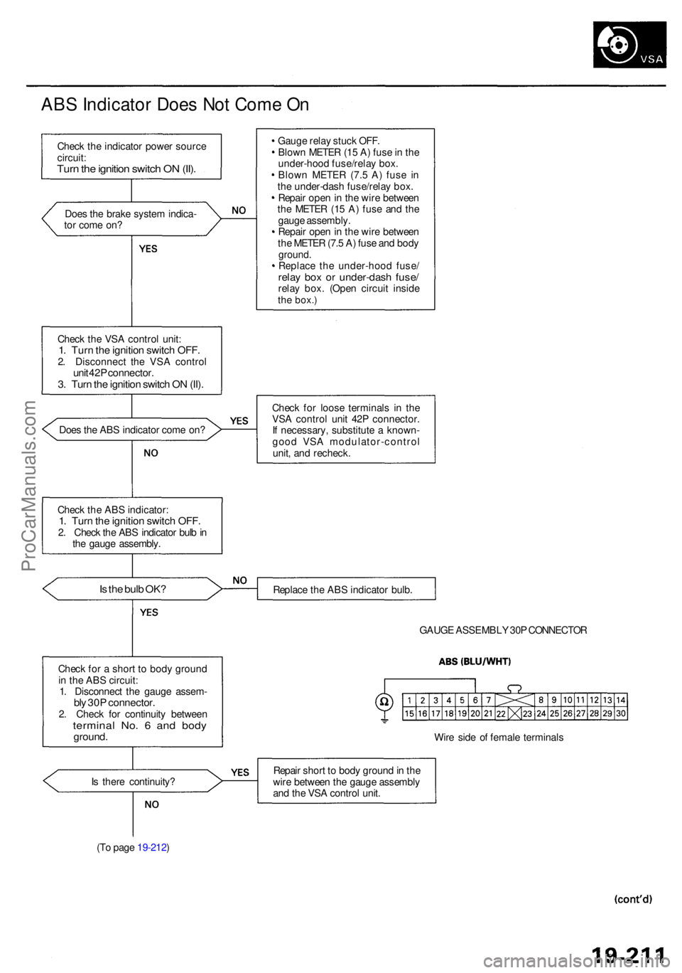
ABS Indicato r Doe s No t Com e O n
Chec k th e indicato r powe r sourc e
circuit :
Turn th e ignitio n switc h O N (II) .
Doe s th e brak e syste m indica -
to r com e on ?
Chec k th e VS A contro l unit :
1. Tur n th e ignitio n switc h OFF .2. Disconnec t th e VS A contro lunit 42 P connector .3. Tur n th e ignitio n switc h O N (II) .
Doe s th e AB S indicato r com e on ?
Chec k th e AB S indicator :
1. Tur n th e ignitio n switc h OFF .2. Chec k th e AB S indicato r bul b in
th e gaug e assembly .
Is th e bul b OK ?
Chec k fo r a shor t t o bod y groun d
i n th e AB S circuit :
1 . Disconnec t th e gaug e assem -
bly 30 P connector .2. Chec k fo r continuit y betwee nterminal No . 6 an d bod yground .
Is ther e continuity ?
(T o pag e 19-212 ) Gaug
e rela y stuc k OFF .
Blow n METE R (1 5 A ) fus e in th e
under-hoo d fuse/rela y box .
Blow n METE R (7. 5 A ) fus e i n
th e under-das h fuse/rela y box .
Repai r ope n in th e wir e betwee n
th e METE R (1 5 A ) fus e an d th e
gaug e assembly .
Repai r ope n in th e wir e betwee n
th e METE R (7. 5 A ) fus e an d bod y
ground .Replac e th e under-hoo d fuse /relay bo x o r under-das h fuse /relay box . (Ope n circui t insid ethe box. )
Check fo r loos e terminal s i n th e
VS A contro l uni t 42 P connector .
I f necessary , substitut e a known -
goo d VS A modulator-contro l
unit , an d recheck .
Replac e th e AB S indicato r bulb .
GAUG E ASSEMBL Y 30 P CONNECTO R
Wir e sid e o f femal e terminal s
Repai r shor t t o bod y groun d in th e
wir e betwee n th e gaug e assembl y
an d th e VS A contro l unit .
ProCarManuals.com
Page 1250 of 1954
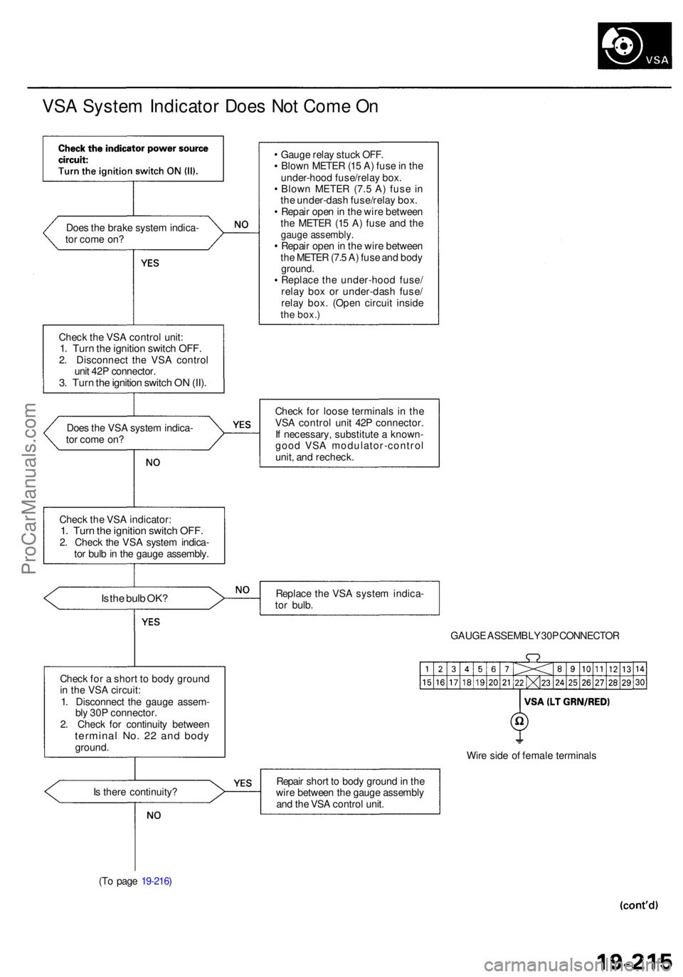
VSA Syste m Indicato r Doe s No t Com e O n
Doe s th e brak e syste m indica -
to r com e on ?
Chec k th e VS A contro l unit :
1. Tur n th e ignitio n switc h OFF .2. Disconnec t th e VS A contro l
uni t 42 P connector .
3. Tur n th e ignitio n switc h O N (II) .
Doe s th e VS A syste m indica -
to r com e on ?
Chec k th e VS A indicator :
1. Tur n th e ignitio n switc h OFF .2. Chec k th e VS A syste m indica -
to r bul b in th e gaug e assembly .
Is th e bul b OK ?
Chec k fo r a shor t t o bod y groun d
i n th e VS A circuit :
1 . Disconnec t th e gaug e assem -
bl y 30 P connector.
2 . Chec k fo r continuit y betwee n
termina l No . 2 2 an d bod yground .
I s ther e continuity ?
(T o pag e 19-216 ) Gaug
e rela y stuc k OFF .
Blow n METE R (1 5 A ) fus e in th e
under-hoo d fuse/rela y box .
Blow n METE R (7. 5 A ) fus e i n
th e under-das h fuse/rela y box .
Repai r ope n in th e wir e betwee n
th e METE R (1 5 A ) fus e an d th e
gaug e assembly .Repair ope n in th e wir e betwee n
th e METE R (7. 5 A ) fus e an d bod y
ground .Replac e th e under-hoo d fuse /
rela y bo x o r under-das h fuse /
rela y box . (Ope n circui t insid e
the box. )
Chec k fo r loos e terminal s i n th e
VS A contro l uni t 42 P connector .
I f necessary , substitut e a known -
goo d VS A modulator-contro l
unit , an d recheck .
Replac e th e VS A syste m indica -
to r bulb .
GAUGE ASSEMBL Y 30 P CONNECTO R
Wir e sid e o f femal e terminal s
Repai r shor t t o bod y groun d in th e
wir e betwee n th e gaug e assembl y
an d th e VS A contro l unit .
ProCarManuals.com
Page 1254 of 1954
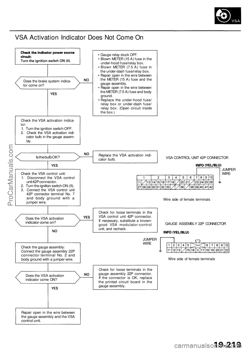
VSA Activation Indicator Does Not Come On
Does the brake system indica-
tor come on?
Check the VSA activation indica-
tor:
1. Turn the ignition switch OFF.
2. Check the VSA activation indi-
cator bulb in the gauge assem-
bly.
Is the bulb OK?
Check the VSA control unit:
1. Disconnect the VSA control
unit 42P connector.
2. Turn the ignition switch ON (II).
3. Connect the VSA control unit
42P connector terminal No. 7
and body ground with a
jumper wire.
Does the VSA activation
indicator come on?
Check the gauge assembly:
Connect the gauge assembly 22P
connector terminal No. 2 and
body ground with a jumper wire.
Does the VSA activation
indicator come ON?
Repair open in the wire between
the gauge assembly and the VSA
control unit.
Gauge relay stuck OFF.
Blown METER (15 A) fuse in the
under-hood fuse/relay box.
Blown METER (7.5 A) fuse in
the under-dash fuse/relay box.
Repair open in the wire between
the METER (15 A) fuse and the
gauge assembly.
Repair open in the wire between
the METER (7.5 A) fuse and body
ground.
Replace the under-hood fuse/
relay box or under-dash fuse/
relay box. (Open circuit inside
the
box.)
Replace the VSA activation indi-
cator bulb.
VSA CONTROL UNIT 42P CONNECTOR
JUMPER
WIRE
Check for loose terminals in the
VSA control unit 42P connector.
If necessary, substitute a known-
good VSA modulator-control
unit, and recheck.
JUMPER
WIRE
Wire side of female terminals
GAUGE ASSEMBLY 22P CONNECTOR
Wire side of female terminals
Check for loose terminals in the
gauge assembly 22P connector.
If the connector is OK, replace
the printed circuit board in the
gauge assembly.ProCarManuals.com