1996 ACURA RL KA9 bulb
[x] Cancel search: bulbPage 1364 of 1954

Removal — '99 - 0 1 Model s
CAUTION : Whe n pryin g wit h a flat-ti p screwdriver , wra p it wit h protectiv e tap e t o preven t damage .
NOTE : Tak e car e no t t o scratc h th e consol e panel , rea r console , fron t seat , an d relate d parts .
Disassembl e i n numbere d sequence .
Bolt, scre w location s
6 x 1. 0 m m9.8 N- m (1. 0 kgf-m ,
7. 2 Ibf-ft ) Cli
p location s
SEA T HEATE R
SWITCH(driver's )
HOOKS
CIGARETT E
LIGHTE R
CONNECTO R
ACCESSOR YPOWER SOCKE T
Installatio n i s th e revers e o f th e remova l procedure .
NOTE:
If necessary , replac e an y damage d clips .
Mak e sur e th e wir e harnesse s ar e no t pinched .
Mak e sur e th e connector s an d bul b socke t ar e connecte d properly .
BEVERAG E
HOLDE R TRA Y
Disconnec t th e beverag e holde rbulb socket .
BEVERAG E HOLDE R
REA R CONSOL E
Disconnec t th e accessor y
power socket , an d detac hthe harnes s clip .
REA R HEATE R
COVE R
CONSOL
E PANE L
Disconnec t th e cigarett elighter connector .
HOOKS
A/
T GEA R POSITIO N
INDICATO R TRI MDisconnec t th e sea theate r switc h connector sand indicato r ligh t bul bsocket .
INDICATO R LIGH TBULB SOCKE T
CONNECTORS
HOO K
BEVERAG EHOLDER
BUL B SOCKE THARNES SCLIP
SEA T HEATE RSWITCH(passenger's )
ProCarManuals.com
Page 1470 of 1954
Climate Contro l Uni t
Replacemen t Bul b Replacemen t
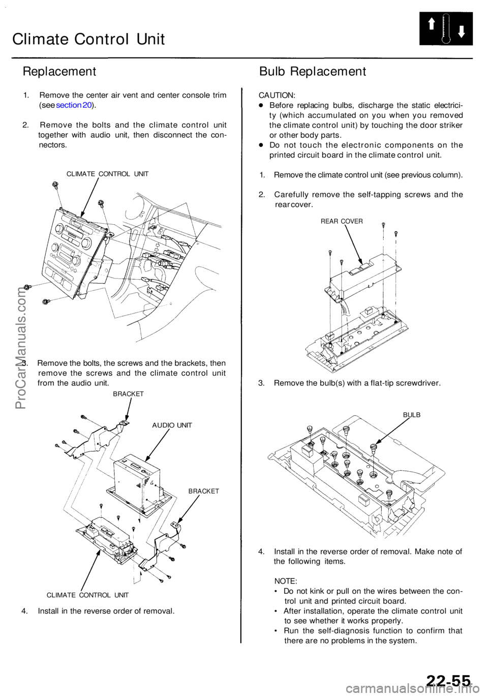
1. Remov e th e cente r ai r ven t an d cente r consol e tri m
(se e sectio n 20 ).
2 . Remov e th e bolt s an d th e climat e contro l uni t
togethe r wit h audi o unit , the n disconnec t th e con -
nectors .
CLIMAT E CONTRO L UNI T
3. Remov e th e bolts , th e screw s an d th e brackets , the n
remov e th e screw s an d th e climat e contro l uni t
fro m th e audi o unit .
BRACKE T
AUDIO UNI T
BRACKE T
CAUTION :
Before replacin g bulbs , discharg e th e stati c electrici -
t y (whic h accumulate d o n yo u whe n yo u remove d
th e climat e contro l unit ) b y touchin g th e doo r strike r
o r othe r bod y parts .
D o no t touc h th e electroni c component s o n th e
printe d circui t boar d in th e climat e contro l unit .
1 . Remov e th e climat e contro l uni t (se e previou s column) .
2 . Carefull y remov e th e self-tappin g screw s an d th e
rea r cover .
REAR COVE R
3. Remov e th e bulb(s ) wit h a flat-ti p screwdriver .
BULB
4. Instal l i n th e revers e orde r o f removal . Mak e not e o f
th e followin g items .
NOTE:
• D o no t kin k o r pul l o n th e wire s betwee n th e con -
tro l uni t an d printe d circui t board .
• Afte r installation , operat e th e climat e contro l uni t
t o se e whethe r i t work s properly .
• Ru n th e self-diagnosi s functio n t o confir m tha t
ther e ar e n o problem s in th e system .CLIMAT E CONTRO L UNI T
4. Instal l i n th e revers e orde r o f removal .
ProCarManuals.com
Page 1526 of 1954
Gauge Assembl y
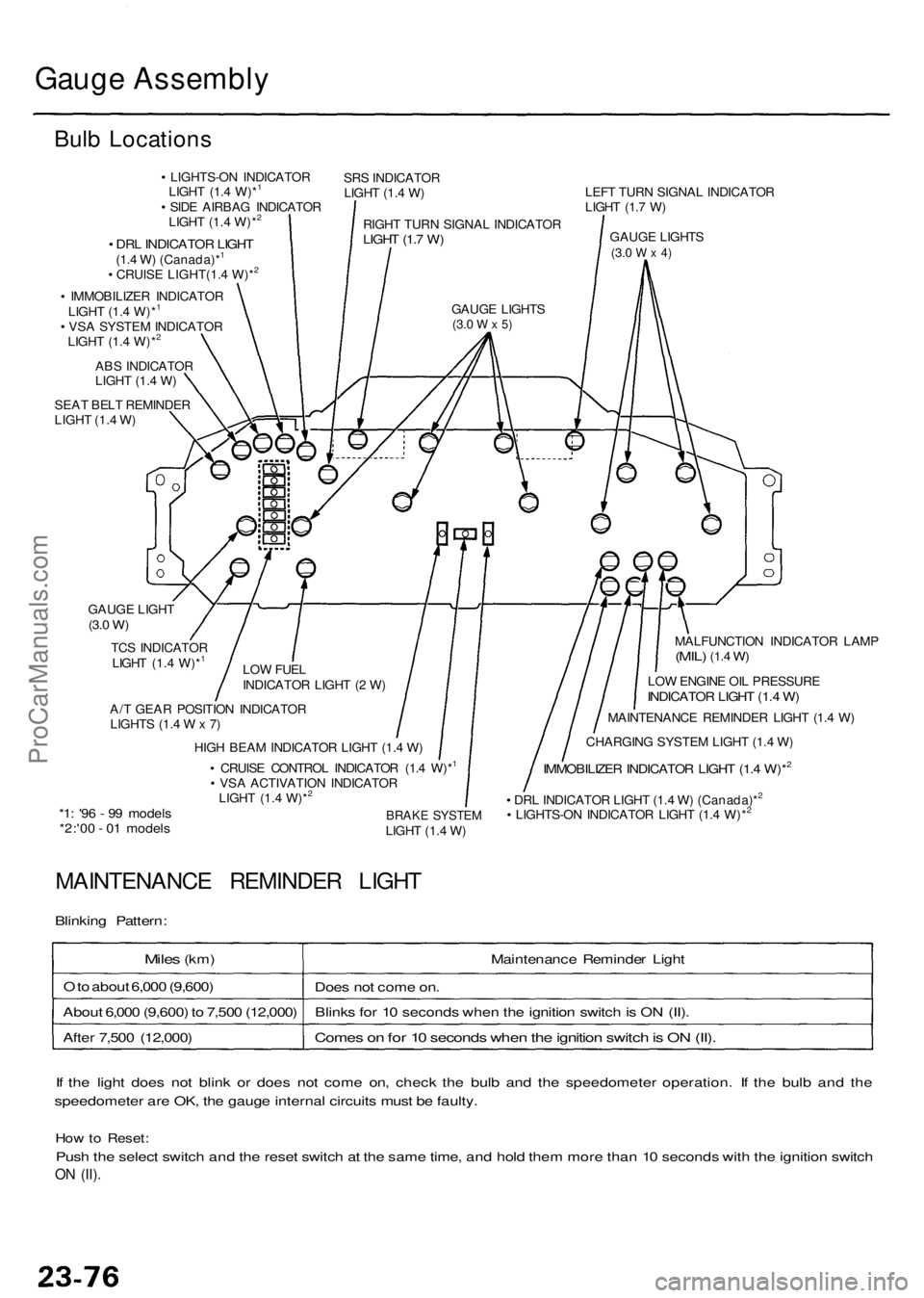
Bulb Location s
• LIGHTS-O N INDICATO R
LIGH T (1. 4 W)*1
• SID E AIRBA G INDICATO R
LIGH T (1. 4 W)*2
SR S INDICATO R
LIGH T (1. 4 W )
RIGH T TUR N SIGNA L INDICATO R
LIGHT (1. 7 W )
GAUG E LIGHT S(3.0 W x 5)
• DR L INDICATO R LIGH T(1.4 W ) (Canada)*1
• CRUIS E LIGHT(1. 4 W)*2
• IMMOBILIZE R INDICATO R
LIGH T (1. 4 W)*1
• VS A SYSTE M INDICATO R
LIGH T (1. 4 W)*2
AB S INDICATO R
LIGH T (1. 4 W )
SEA T BEL T REMINDE R
LIGH T (1. 4 W ) LEF
T TUR N SIGNA L INDICATO R
LIGH T (1. 7 W )
GAUG E LIGHT S
(3.0 W x 4)
MALFUNCTIO N INDICATO R LAM P(MIL) (1.4 W)
LO W ENGIN E OI L PRESSUR EINDICATOR LIGH T (1. 4 W )
MAINTENANC E REMINDE R LIGH T (1. 4 W )
CHARGIN G SYSTE M LIGH T (1. 4 W )
IMMOBILIZE R INDICATO R LIGH T (1. 4 W)*2
• DR L INDICATO R LIGH T (1. 4 W ) (Canada)*2
• LIGHTS-O N INDICATO R LIGH T (1. 4 W)*2BRAK E SYSTE MLIGHT (1. 4 W )
A/
T GEA R POSITIO N INDICATO R
LIGHT S (1. 4 W x 7) LO
W FUE L
INDICATO R LIGH T ( 2 W )
TC
S INDICATO R
LIGH T (1. 4 W)*
1
GAUG E LIGH T(3.0 W )
HIG H BEA M INDICATO R LIGH T (1. 4 W )
• CRUIS E CONTRO L INDICATO R (1. 4 W)*1
• VS A ACTIVATIO N INDICATO R
LIGH T (1. 4 W)*2
*1 : '9 6 - 9 9 model s*2:'00 - 0 1 model s
MAINTENANC E REMINDE R LIGH T
Blinking Pattern :
Miles (km ) Maintenance Reminde r Ligh t
O to abou t 6,00 0 (9,600 )
Does no t com e on .
Abou t 6,00 0 (9,600 ) t o 7,50 0 (12,000 )Blink s fo r 1 0 second s whe n th e ignitio n switc h is O N (II) .
Come s o n fo r 1 0 second s whe n th e ignitio n switc h is O N (II) .Afte r 7,50 0 (12,000 )
I f th e ligh t doe s no t blin k o r doe s no t com e on , chec k th e bul b an d th e speedomete r operation . I f th e bul b an d th e
speedomete r ar e OK , th e gaug e interna l circuit s mus t b e faulty .
How to Reset :
Push th e selec t switc h an d th e rese t switc h a t th e sam e time , an d hol d the m mor e tha n 1 0 second s wit h th e ignitio n switc h
ON (II) .
ProCarManuals.com
Page 1527 of 1954
Gauge Assembl y
Select/Rese t Switc h Tes t
1. Remov e th e instrumen t pane l (se e sectio n 20 ).
2 . Disconnec t th e 5 P connecto r fro m th e switch .
SELECT/RESE TSWITCH
BULBS(0.84 W x 2 )
INSTRUMEN T PANE L
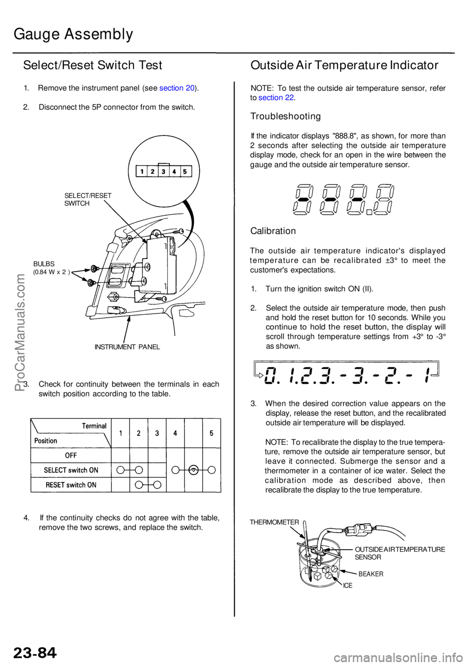
3. Chec k fo r continuit y betwee n th e terminal s i n eac h
switc h positio n accordin g t o th e table .
Outsid e Ai r Temperatur e Indicato r
NOTE: T o tes t th e outsid e ai r temperatur e sensor , refe r
t o sectio n 22 .
Troubleshootin g
If th e indicato r display s "888.8" , a s shown , fo r mor e tha n
2 second s afte r selectin g th e outsid e ai r temperatur e
displa y mode , chec k fo r a n ope n in th e wir e betwee n th e
gaug e an d th e outsid e ai r temperatur e sensor .
Calibratio n
The outsid e ai r temperatur e indicator' s displaye d
temperatur e ca n b e recalibrate d ±3 ° t o mee t th e
customer' s expectations .
1 . Tur n th e ignitio n switc h O N (II) .
2 . Selec t th e outsid e ai r temperatur e mode , the n pus h
an d hol d th e rese t butto n fo r 1 0 seconds . Whil e yo u
continu e t o hol d th e rese t button , th e displa y wil l
scrol l throug h temperatur e setting s fro m +3 ° t o -3 °
a s shown .
3 . Whe n th e desire d correctio n valu e appear s o n th e
display , releas e th e rese t button , an d th e recalibrate d
outsid e ai r temperatur e wil l b e displayed .
NOTE : T o recalibrat e th e displa y to th e tru e tempera -
ture , remov e th e outsid e ai r temperatur e sensor , bu t
leav e i t connected . Submerg e th e senso r an d a
thermomete r i n a containe r o f ic e water . Selec t th e
calibratio n mod e a s describe d above , the n
recalibrat e th e displa y to th e tru e temperature .
THERMOMETE R
OUTSIDE AI R TEMPERATUR ESENSOR
BEAKE R
ICE
4. I f th e continuit y check s d o no t agre e wit h th e table ,
remov e th e tw o screws , an d replac e th e switch .
ProCarManuals.com
Page 1546 of 1954
Lighting Syste m
HID Lam p Syste m Troubleshootin g ('9 9 - 0 4 models )
CAUTION : Neve r tur n o n th e combinatio n ligh t switc h
befor e fittin g th e HI D bulb s t o thei r bul b socket s an d
completin g th e reassembl y o f th e headligh t assembly .
1 . Chec k th e No . 4 5 (2 0 A ) o r No . 4 6 (2 0 A ) fus e in th e
under-hoo d fuse/rela y box .
Are the fuses OK?
YES - G o to ste p 2 .
NO - Replac e th e fuse(s) , an d recheck .
2. Substitut e a known-goo d HI D bul b an d recheck .
Does the headlight low beam come on?
YES-Replac e th e HI D bulb .
N O - G o t o ste p 3 .
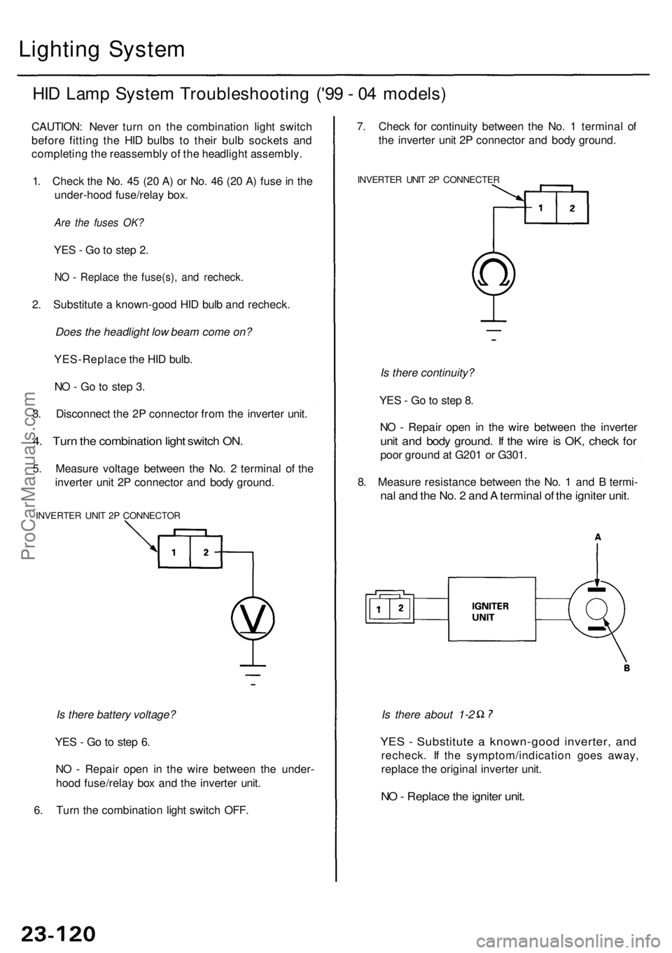
3 . Disconnec t th e 2 P connecto r fro m th e inverte r unit .
4. Tur n th e combinatio n ligh t switc h ON .
5. Measur e voltag e betwee n th e No . 2 termina l o f th e
inverte r uni t 2 P connecto r an d bod y ground .
INVERTE R UNI T 2 P CONNECTO R
Is there battery voltage?
YE S - G o to ste p 6 .
N O - Repai r ope n i n th e wir e betwee n th e under -
hoo d fuse/rela y bo x an d th e inverte r unit .
6 . Tur n th e combinatio n ligh t switc h OFF .
YES - Substitut e a known-goo d inverter , an d
recheck . I f th e symptom/indicatio n goe s away ,
replac e th e origina l inverte r unit .
NO - Replac e th e ignite r unit .
Is there about 1-2
7
. Chec k fo r continuit y betwee n th e No . 1 termina l o f
th e inverte r uni t 2 P connecto r an d bod y ground .
INVERTE R UNI T 2 P CONNECTE R
Is there continuity?
YE S - G o to ste p 8 .
N O - Repai r ope n i n th e wir e betwee n th e inverte r
unit an d bod y ground . I f th e wir e is OK , chec k fo r
poo r groun d a t G20 1 o r G301 .
8 . Measur e resistanc e betwee n th e No . 1 an d B termi -
nal an d th e No . 2 an d A termina l o f th e ignite r unit .
ProCarManuals.com
Page 1548 of 1954
Headlights
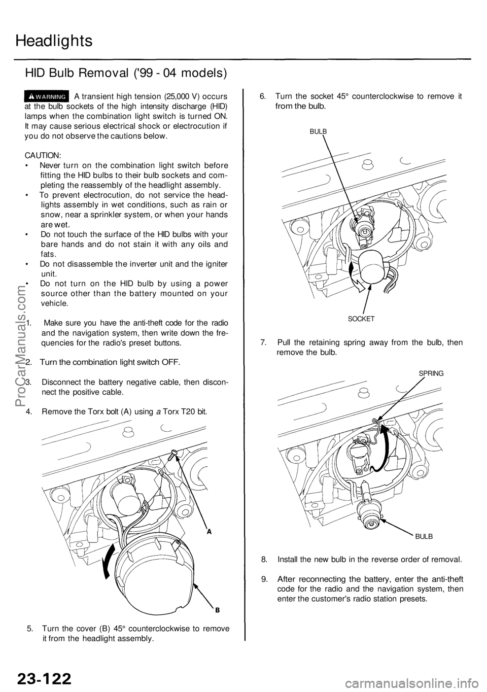
HID Bul b Remova l ('9 9 - 0 4 models )
A transien t hig h tensio n (25,00 0 V ) occur s
a t th e bul b socket s o f th e hig h intensit y discharg e (HID )
lamp s whe n th e combinatio n ligh t switc h is turne d ON .
I t ma y caus e seriou s electrica l shoc k o r electrocutio n if
yo u d o no t observ e th e caution s below .
CAUTION :
• Neve r tur n o n th e combinatio n ligh t switc h befor e
fittin g th e HI D bulb s t o thei r bul b socket s an d com -
pletin g th e reassembl y o f th e headligh t assembly .
• T o preven t electrocution , d o no t servic e th e head -
light s assembl y i n we t conditions , suc h a s rai n o r
snow , nea r a sprinkle r system , o r whe n you r hand s
are wet .
• D o no t touc h th e surfac e o f th e HI D bulb s wit h you r
bar e hand s an d d o no t stai n i t wit h an y oil s an d
fats .
• D o no t disassembl e th e inverte r uni t an d th e ignite r
unit .
• D o no t tur n o n th e HI D bul b b y usin g a powe r
sourc e othe r tha n th e batter y mounte d o n you r
vehicle .
1. Mak e sur e yo u hav e th e anti-thef t cod e fo r th e radi o
an d th e navigatio n system , the n writ e dow n th e fre -
quencie s fo r th e radio' s prese t buttons .
2. Tur n th e combinatio n ligh t switc h OFF .
3. Disconnec t th e batter y negativ e cable , the n discon -
nec t th e positiv e cable .
4 . Remov e th e Tor x bol t (A ) usin g a Tor x T2 0 bit .
5 . Tur n th e cove r (B ) 45 ° counterclockwis e t o remov e
i t fro m th e headligh t assembly . 8
. Instal l th e ne w bul b in th e revers e orde r o f removal .
9. Afte r reconnectin g th e battery , ente r th e anti-thef t
code fo r th e radi o an d th e navigatio n system , the n
ente r th e customer' s radi o statio n presets .
BULB
SPRIN G
6. Tur n th e socke t 45 ° counterclockwis e t o remov e i t
fro m th e bulb .
BULB
7. Pul l th e retainin g sprin g awa y fro m th e bulb , the n
remov e th e bulb .
SOCKE T
ProCarManuals.com
Page 1552 of 1954
Fog Light s
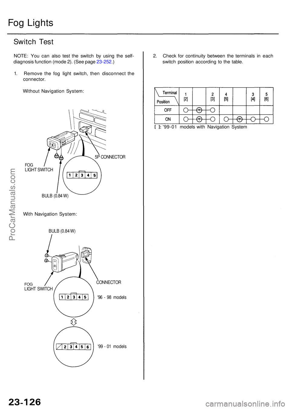
Switch Tes t
NOTE : Yo u ca n als o tes t th e switc h b y usin g th e self -
diagnosi s functio n (mod e 2) . (Se e pag e 23-252 .)
1 . Remov e th e fo g ligh t switch , the n disconnec t th e
connector .
Withou t Navigatio n System :
FOGLIGH T SWITC H
BUL B (0.8 4 W ) 5
P CONNECTO R
With Navigatio n System : 2
. Chec k fo r continuit y betwee n th e terminal s i n eac h
switc h positio n accordin g t o th e table .
'99-0 1 model s wit h Navigatio n Syste m
BULB (0.8 4 W )
FO GLIGH T SWITC H
CONNECTO R
'96 - 9 8 model s
'9 9 - 0 1 model s
ProCarManuals.com
Page 1553 of 1954
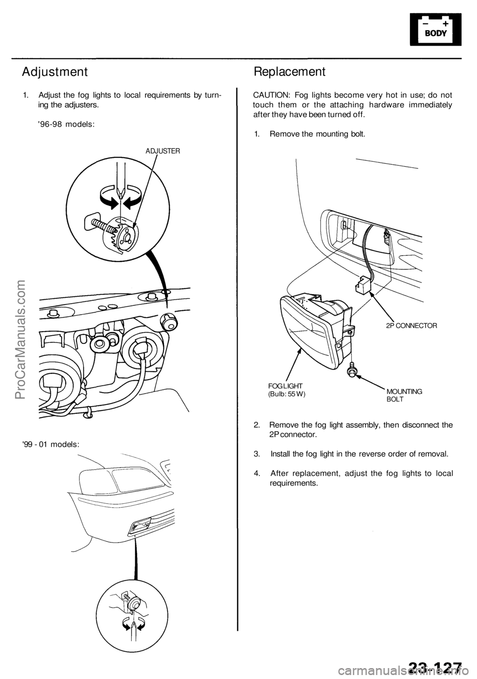
Adjustment
1. Adjus t th e fo g light s t o loca l requirement s b y turn -
ing th e adjusters .
'96-98 models :
ADJUSTE R
Replacemen t
CAUTION: Fo g light s becom e ver y ho t i n use ; d o no t
touc h the m o r th e attachin g hardwar e immediatel y
afte r the y hav e bee n turne d off .
1 . Remov e th e mountin g bolt .
2P CONNECTO R
MOUNTINGBOLT
FOG LIGH T
(Bulb : 5 5 W )
2. Remov e th e fo g ligh t assembly , the n disconnec t th e
2 P connector .
3 . Instal l th e fo g ligh t i n th e revers e orde r o f removal .
4 . Afte r replacement , adjus t th e fo g light s t o loca l
requirements .
'9
9 - 0 1 models :
ProCarManuals.com