1996 ACURA RL KA9 oil
[x] Cancel search: oilPage 149 of 1954
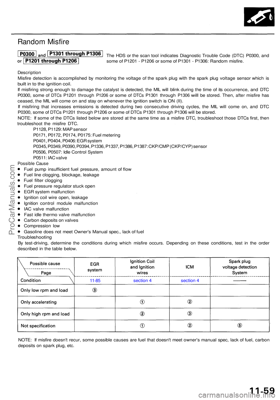
Random Misfir e
The HD S o r th e sca n too l indicate s Diagnosti c Troubl e Cod e (DTC ) P0300 , an d
som e o f P120 1 - P120 6 o r som e o f P130 1 - P1306 : Rando m misfire .
Descriptio n
Misfire detectio n i s accomplishe d b y monitorin g th e voltag e o f th e spar k plu g wit h th e spar k plu g voltag e senso r whic h i s
buil t i n to th e ignitio n coil .
If misfirin g stron g enoug h t o damag e th e catalys t i s detected , th e MI L wil l blin k durin g th e tim e o f it s occurrence , an d DT C
P0300 , som e
of DTC s P120 1 throug h P1206 or som e of DTC s P130 1 throug h P1306 will be stored . Then , after misfir e has
ceased , th e MI L wil l com e o n an d sta y o n wheneve r th e ignitio n switc h is O N (II) .
I f misfirin g tha t increase s emission s i s detecte d during two consecutiv e drivin g cycles , th e MI L wil l com e on , an d DT C
P0300 , som e o f DTC s P120 1 throug h P120 6 o r som e o f DTC s P130 1 throug h P130 6 wil l b e stored .
NOTE : I f som e o f th e DTC s liste d belo w ar e store d a t th e sam e tim e a s a misfir e DTC , troubleshoo t thos e DTC s first , the n
troubleshoo t th e misfir e DTC .
P1128 , P1129 : MA P senso r
P0171 , P0172 , P0174 , P0175 : Fue l meterin g
P0401 , P0404 , P0406 : EG R syste m
P0345 , P0349 , P0390 , P0394 , P1336 , P1337 , P1386 , P1387 : CKP/CM P (CKP/CYP ) senso r
P0506 , P0507 : Idl e Contro l Syste m
P0511 : IA C valv e
Possibl e Caus e
Fuel pum p insufficien t fue l pressure , amoun t o f flo w
Fue l lin e clogging , blockage , leakag e
Fue l filte r cloggin g
Fue l pressur e regulato r stuc k ope n
EG R syste m malfunctio n
Ignitio n coi l wir e open , leakag e
Ignitio n contro l modul e malfunctio n
IA C valv e malfunctio n
Fas t idl e therm o valv e malfunctio n
Carbo n deposit s o n valve s
Compressio n lo w
Gasolin e doe s no t mee t Owner' s Manua l spec. , lac k o f fue l
Troubleshootin g
By test-driving , determin e th e condition s during which misfir e occurs . Dependin g o n thes e conditions , tes t i n th e orde r
describe d i n th e tabl e below .
NOTE : I f misfir e doesn' t recur , som e possibl e cause s ar e fue l tha t doesn' t mee t owner' s manua l spec , lac k o f fuel , carbo n
deposit s o n spar k plug , etc .
11-8 5 sectio n 4 section 4
ProCarManuals.com
Page 150 of 1954

PGM-FI System
Description
Misfire detection is accomplished by monitoring the voltage of the spark plug with the spark plug voltage sensor which is
built into the ignition coil.
If misfiring strong enough to damage the catalyst is detected, the MIL will blink during the time of its occurrence, and a
misfire DTC will be stored. Then, after the misfire has ceased, the MIL will come on and stay on whenever the ignition
switch is ON (II).
If misfiring that increases emissions is detected during two consecutive driving cycles, the MIL will come on, and a misfire
DTC will be stored.
NOTE: If some of the DTCs listed below are stored at the same time as a misfire DTC, troubleshoot those DTCs first, then
troubleshoot the misfire DTC.
P1128, P1129: MAP sensor
P0171, P0172, P0174, P0175: Fuel supply system
P0401, P0404, P0406: EGR system
P1316, P1317, P1318, P1319: Spark Plug Voltage Detection System
P0345, P0349, P1336, P1337: CKP sensor
P0390, P0394, P1386, P1387: CMP (CYP) sensor
Possible Cause
Injector clogging, fuel leakage, air leakage
Injector circuit open or shorted
Injector resistor malfunction
Spark plug carbon deposits, fouling, malfunction
Ignition coil malfunction
ICM malfunction
Compression low
11-60
The HDS or the scan tool indicates Diagnostic Trouble Code (DTC) P1201 or P1301: Cylinder 1 mis-
fire detected.
The HDS or the scan tool indicates Diagnostic Trouble Code (DTC) P1202 or P1302: Cylinder 2 mis-
fire detected.
The HDS or the scan tool indicates Diagnostic Trouble Code (DTC) P1203 or P1303: Cylinder 3 mis-
fire detected.
The HDS or the scan tool indicates Diagnostic Trouble Code (DTC) P1204 or P1304: Cylinder 4 mis-
fire detected.
The HDS or the scan tool indicates Diagnostic Trouble Code (DTC) P1205 or P1305: Cylinder 5 mis-
fire detected.
The HDS or the scan tool indicates Diagnostic Trouble Code (DTC) P1206 or P1306: Cylinder 6 mis-
fire detected.
Misfire Detected in One CylinderProCarManuals.com
Page 151 of 1954
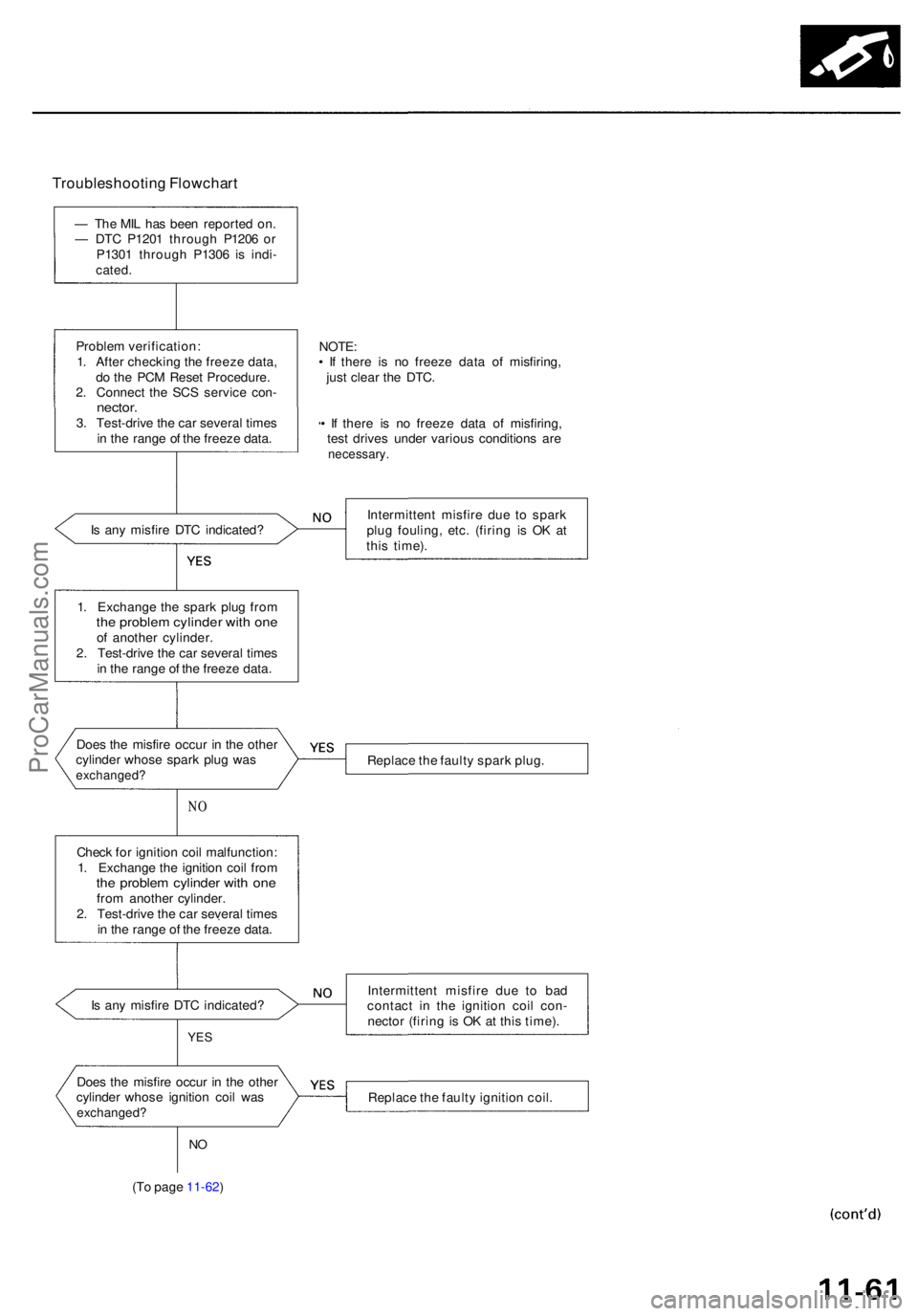
Troubleshooting Flowchar t
— Th e MI L ha s bee n reporte d on .
— DT C P120 1 throug h P120 6 o r
P130 1 throug h P130 6 i s indi -
cated .
Proble m verification :
1 . Afte r checkin g th e freez e data ,
d o th e PC M Rese t Procedure .
2 . Connec t th e SC S servic e con -
nector .3. Test-driv e th e ca r severa l time s
i n th e rang e o f th e freez e data .
I s an y misfir e DT C indicated ?
NO
Chec k fo r ignitio n coi l malfunction :
1 . Exchang e th e ignitio n coi l fro m
the proble m cylinde r wit h on efrom anothe r cylinder .
2 . Test-driv e th e ca r severa l time s
i n th e rang e o f th e freez e data .
I s an y misfir e DT C indicated ?
YES
NO
(T o pag e 11-62 )
NOTE:• I f ther e i s n o freez e dat a o f misfiring ,
jus t clea r th e DTC .
• I f ther e i s n o freez e dat a o f misfiring ,
tes t drive s unde r variou s condition s ar e
necessary .
Intermitten t misfir e du e t o spar k
plu g fouling , etc . (firin g i s O K a t
thi s time) .
Replac e th e fault y spar k plug .
Intermitten t misfir e du e t o ba d
contac t i n th e ignitio n coi l con -
necto r (firin g is O K a t thi s time) .
Replac e th e fault y ignitio n coil .
Doe
s th e misfir e occu r i n th e othe r
cylinde r whos e spar k plu g wa s
exchanged ?
Does th e misfir e occu r i n th e othe r
cylinde r whos e ignitio n coi l wa s
exchanged ?
1. Exchang e th e spar k plu g fro mthe proble m cylinde r wit h on eof anothe r cylinder .
2 . Test-driv e th e ca r severa l time s
i n th e rang e o f th e freez e data .
ProCarManuals.com
Page 154 of 1954

PGM-FI Syste m
Crankshaf t Position/Camshaf t Positio n (CKP/CMP ) (Crankshaf t
Position/Cylinde r Positio n (CKP/CYP) ) Senso r
The HD S o r th e sca n too l indicate s Diagnosti c Troubl e Cod e (DTC ) P0345 : A malfunctio n i n th e circui t o f th e
Crankshaf t Positio n (CKP ) senso r 1 .
Th e HD S o r th e sca n too l indicate s Diagnosti c Troubl e Cod e (DTC ) P0349 : A n intermitten t interruptio n proble m of
th e Crankshaf t Positio n (CKP ) senso r 1 .
Th e HD S o r th e sca n too l indicate s Diagnosti c Troubl e Cod e (DTC ) P0390 : A malfunctio n in th e circui t o f th e Camshaf t
Positio n (CMP ) (Cylinde r Positio n (CYP) ) senso r 1 .
Th e HD S o r th e sca n too l indicate s Diagnosti c Troubl e Cod e (DTC ) P0394 : A n intermitten t interruptio n proble m
o f th e Camshaf t Positio n (CMP ) (Cylinde r Positio n (CYP) ) senso r 1 .
Th e HD S o r th e sca n too l indicate s Diagnosti c Troubl e Cod e (DTC ) P1336 : A n intermitten t interruptio n proble m o f
th e Crankshaf t Positio n (CKP ) senso r 2 .
I Th e HD S o r th e sca n too l indicate s Diagnosti c Troubl e Cod e (DTC ) P1337 : A malfunctio n i n th e circui t o f th e
' Crankshaf t Positio n (CKP ) senso r 2 .
Th e HD S o r th e sca n too l indicate s Diagnosti c Troubl e Cod e (DTC ) P1386 : A n intermitten t interruptio n proble m
o f th e Camshaf t Positio n (CMP ) (Cylinde r Positio n (CYP) ) senso r 2 .
Th e HD S o r th e sca n too l indicate s Diagnosti c Troubl e Cod e (DTC ) P1387 : A malfunctio n i n th e circui t o f th e
Camshaf t Positio n (CMP ) (Cylinde r Positio n (CYP) ) senso r 2 .
Th e CK P Senso r determine s timin g fo r injectio n an d ignitio n o f eac h cylinde r an d als o detect s engin e speed .
Th e CM P (CYP ) Senso r detect s th e positio n o f No . 1 cylinde r fo r sequentia l injectio n t o eac h cylinder . Th e CKP/CM P
(CKP/CYP ) Senso r i s installe d behin d th e fron t camshaf t pulley .
— Th e MI L ha s bee n reporte d on .— DT C P0345 , P0349 , P0390 ,P0394, P1336 , P1337 , P138 6
and/o r P138 7 ar e stored .
Proble m verification :
1. D o th e PC M Rese t Procedure .2. Star t th e engine .
Check fo r a n ope n i n th e CKP /CMP (CKP/CYP ) sensor :1. Tur n th e ignitio n switc h OFF .2. Disconnec t th e CKP/CM P(CKP/CYP) 8 P connector .3. Measur e resistanc e betwee nthe terminal s o f th e indicate dsensor (se e table) .
Is ther e 65 0 - 85 0 fl ?
YE S
Chec k fo r a shor t i n th e CKP /CMP (CKP/CYP ) sensor :Check fo r continuit y t o bod ygroun d o n bot h terminal s o f th eindicate d sensor .
CKP PICK-U PCOIL 2
CM P (CYP ) PICK-U PCOIL 1
N O
Intermitten t failure , syste m is O Kat thi s time . Chec k fo r poo r con -nection s o r loos e terminal s a tC251 , C25 5 (locate d a t righ t shoc ktower) , C13 0 (CKP/CM P (CKP /CYP)) senso r an d PCM .
Replac e th e CKP/CM P (CKP/CYP )sensor (se e sectio n 6) .
CK P PICK-U PCOIL1
CMP (CYP ) PICK-U PCOIL 2
CKP/CM P (CKP/CYP ) SENSO R 8 P CONNECTO R
(To pag e 11-65 )Termina l sid e o f mal e terminal s
Is DT C P0345 , P0349 , P0390 , P0394 ,P1336, P1337 , P138 6 and/o r P138 7indicated ?
ProCarManuals.com
Page 210 of 1954
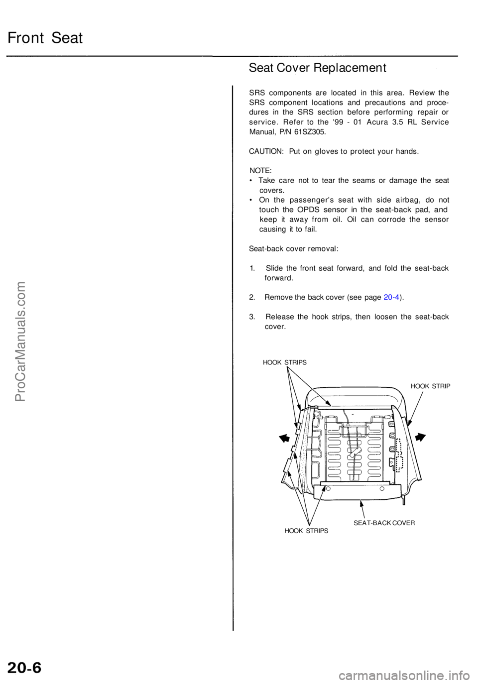
Front Sea t
Seat Cove r Replacemen t
SRS component s ar e locate d i n thi s area . Revie w th e
SR S componen t location s an d precaution s an d proce -
dure s i n th e SR S sectio n befor e performin g repai r o r
service . Refe r t o th e '9 9 - 0 1 Acur a 3. 5 R L Servic e
Manual , P/ N 61SZ305 .
CAUTION : Pu t o n glove s t o protec t you r hands .
NOTE:
• Tak e car e no t t o tea r th e seam s o r damag e th e sea t
covers .
• O n th e passenger' s sea t wit h sid e airbag , d o no t
touc h th e OPD S senso r i n th e seat-bac k pad , an d
kee p i t awa y fro m oil . Oi l ca n corrod e th e senso r
causin g i t t o fail .
Seat-bac k cove r removal :
1 . Slid e th e fron t sea t forward , an d fol d th e seat-bac k
forward .
2 . Remov e th e bac k cove r (se e pag e 20-4 ).
3 . Releas e th e hoo k strips , the n loose n th e seat-bac k
cover.
HOOK STRIP S
HOOK STRI P
SEAT-BAC K COVE R
HOO K STRIP S
ProCarManuals.com
Page 309 of 1954

Lubrication Points
For the details of lubrication points and types of lubricants to be applied, refer to the Illustrated Index and various work
procedures (such as Assembly/Reassembly, Replacement, Overhaul, Installation, etc.) contained in each section.
No.
1
2
3
4
5
6
7
8
9
10
11
12
13
14
15
16
17
18
19
20
21
22
LUBRICATION POINTS
Engine
Transmission
Brake line (Includes ABS line)
Power steering gearbox
Steering boots
Throttle cable end
Steering ball joints
Shift lever (Automatic transmission)
Pedal linkage
Intermediate shaft
Brake master cylinder pushrod
Fuel
fill
lid
Battery terminals
Trunk hinges and latch
Door hinges upper and lower
Door opening detents
Hood hinges and hood latch
Brake line joints (Front and rear wheelhouse)
Caliper Piston boot, caliper
Pins and boots
Power steering system
Differential
A/C compressor
API SERVICE LABEL API CERTIFICATION SEAL
LUBRICANT
API Service Grade: Use SJ "Energy Conserving" grade oil.
The oil container may also display the API Certification
seal shown below. Make sure it says "For Gasoline
Engines."
SAE Viscosity: See chart below.
Honda ATF-Z1 (ATF)*1
Genuine Honda DOT3 brake fluid*2
Steering grease P/N 08733 - B070E
Multi-purpose grease
Honda White Lithium Grease
Rust preventive
Silicone grease
Genuine Honda power steering fluid*3
Hypoid gear Oil API GL4 or GL5
Viscosity:
at above -18°C (0°F): SAE 90
at less than -18°C (0°F): SAE 80W-90
Compressor oil:
DENSO: ND-OIL8 (P/N) 38897 - PR7 - A01 AH or 38899 -
PR7-A01)
(For Refrigerant: HFC-134a (R-134a))
Recommended engine oil
viscosity for ambient
temperature ranges
*1: Always use Honda ATF-Z1 (ATF). Using a non-Honda ATF can affect shift quality.
*2: Always use Genuine Honda DOT3 Brake Fluid. Using a non-Honda brake fluid can cause corrosion and decrease the
life of the system.
*3: Always use Genuine Honda Power Steering Fluid. Using any other type of power steering fluid or automatic transmis-
sion fluid can cause increased wear and poor steering in cold weather.ProCarManuals.com
Page 330 of 1954
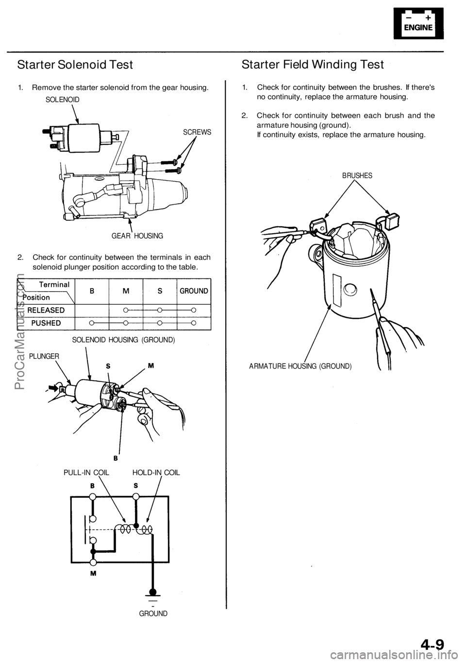
Starter Solenoid Test
1. Remove the starter solenoid from the gear housing.
SOLENOID
SCREWS
GEAR HOUSING
2. Check for continuity between the terminals in each
solenoid plunger position according to the table.
PLUNGER
SOLENOID HOUSING (GROUND)
Starter Field Winding Test
1. Check for continuity between the brushes. If there's
no continuity, replace the armature housing.
2. Check for continuity between each brush and the
armature housing (ground).
If continuity exists, replace the armature housing.
BRUSHES
ARMATURE HOUSING (GROUND)
GROUND
PULL-IN COIL
HOLD-IN COILProCarManuals.com
Page 332 of 1954
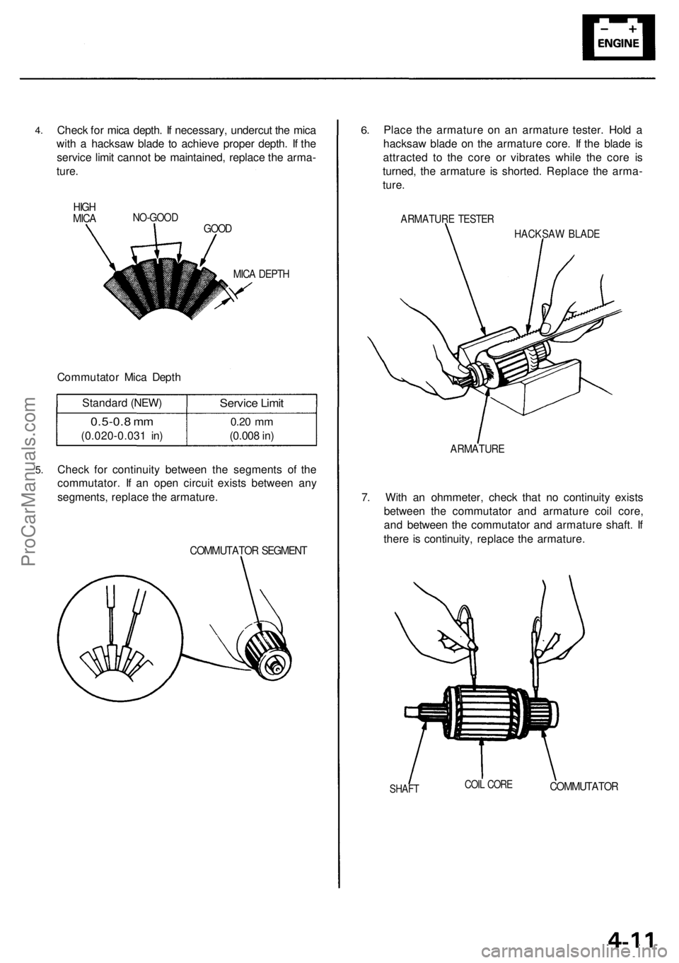
4.
Check for mica depth. If necessary, undercut the mica
with a hacksaw blade to achieve proper depth. If the
service limit cannot be maintained, replace the arma-
ture.
NO-GOOD
GOOD
MICA DEPTH
Commutator Mica Depth
Standard (NEW)
0.5-0.8 mm
(0.020-0.031 in)
Service Limit
0.20
mm
(0.008 in)
5.
Check for continuity between the segments of the
commutator. If an open circuit exists between any
segments, replace the armature.
COMMUTATOR SEGMENT
6.
Place the armature on an armature tester. Hold a
hacksaw blade on the armature core. If the blade is
attracted to the core or vibrates while the core is
turned, the armature is shorted. Replace the arma-
ture.
ARMATURE TESTER
HACKSAW BLADE
ARMATURE
7. With an ohmmeter, check that no continuity exists
between the commutator and armature coil core,
and between the commutator and armature shaft. If
there is continuity, replace the armature.
SHAFT
COIL CORE
COMMUTATOR
HIGH
MICAProCarManuals.com