Page 333 of 1954

Starting Syste m
Starte r Brus h Holde r Tes t
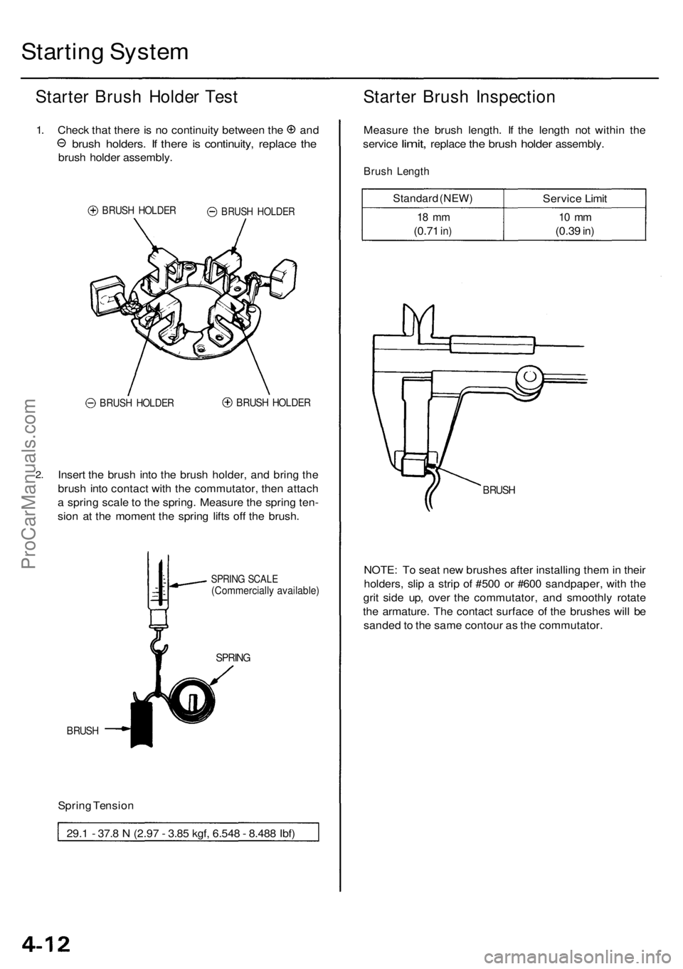
1.Chec k tha t ther e is n o continuit y betwee n th e an d
brush holders . I f ther e i s continuity , replac e th e
brus h holde r assembly .
BRUSH HOLDE R
BRUSH HOLDE RBRUSH HOLDE R
2.Inser t th e brus h int o th e brus h holder , an d brin g th e
brus h int o contac t wit h th e commutator , the n attac h
a sprin g scal e to th e spring . Measur e th e sprin g ten -
sio n a t th e momen t th e sprin g lift s of f th e brush .
SPRIN G SCAL E(Commerciall y available )
SPRING
BRUSH
Spring Tensio n
29. 1 - 37. 8 N (2.9 7 - 3.8 5 kgf , 6.54 8 - 8.48 8 Ibf )
Starte r Brus h Inspectio n
Measure th e brus h length . I f th e lengt h no t withi n th e
servic e
limit, replac e the brus h holde r assembly .
Brush Lengt h
Standar d (NEW )
18 m m
(0.7 1 in)
Servic e Limi t
10 m m
(0.3 9 in)
BRUS H
NOTE : T o sea t ne w brushe s afte r installin g the m in thei r
holders , sli p a stri p o f #50 0 o r #60 0 sandpaper , wit h th e
gri t sid e up , ove r th e commutator , an d smoothl y rotat e
th e armature . Th e contac t surfac e o f th e brushe s wil l b e
sande d to th e sam e contou r a s th e commutator .
BRUSH HOLDE R
ProCarManuals.com
Page 350 of 1954

Rectifier Test
NOTE: The diodes are designed to allow current to pass
in one direction while blocking it in the opposite direc-
tion. Since the alternator rectifier is made up of eight
diodes (four pairs), each diode must be tested for conti-
nuity in both directions with an ohmmeter that has diode
checking capability; a total of 16 checks.
1.
Check for continuity in each direction, between the
B and P, and between the E (ground) and P termi-
nals of each diode pair. All diodes should have con-
tinuity in only one direction.
2.
If any of the eight diodes fails, replace the rectifier
assembly. (Diodes are not available separately.)
Alternator Brush Inspection
1. Remove the end cover, then take out the brush holder
by removing its two screws.
2. Measure the length of the brushes with a vernier
caliper.
Alternator Brush Length:
Standard: 10.5 mm (0.41 in)
Service Limit: 1.5 mm (0.06 in)
ALTERNATOR BRUSHES
VERNIER CALIPER
If the brushes are less than the service limit, replace
the alternator brush assembly.ProCarManuals.com
Page 865 of 1954

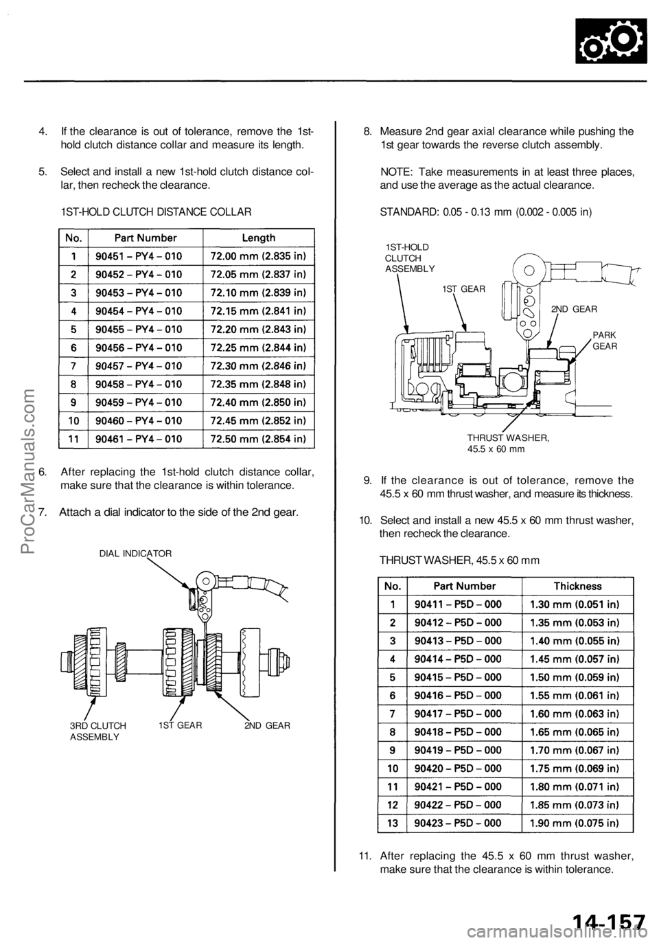
4. I f th e clearanc e i s ou t o f tolerance , remov e th e 1st -
hol d clutc h distanc e colla r an d measur e it s length .
5 . Selec t an d instal l a ne w 1st-hol d clutc h distanc e col -
lar , the n rechec k th e clearance .
1ST-HOLD CLUTC H DISTANC E COLLA R
6. Afte r replacin g th e 1st-hol d clutc h distanc e collar ,
mak e sur e tha t th e clearanc e is withi n tolerance .
7. Attac h a dia l indicato r t o th e sid e o f th e 2n d gear .
DIAL INDICATO R
3R D CLUTC H
ASSEMBL Y1ST GEA R2ND GEA R
8. Measur e 2n d gea r axia l clearanc e whil e pushin g th e
1s t gea r toward s th e revers e clutc h assembly .
NOTE : Tak e measurement s i n a t leas t thre e places ,
an d us e th e averag e a s th e actua l clearance .
STANDARD : 0.0 5 - 0.1 3 m m (0.00 2 - 0.00 5 in )
11. Afte r replacin g th e 45. 5 x 6 0 m m thrus t washer ,
mak e sur e tha t th e clearanc e is withi n tolerance .
9
. I f th e clearanc e i s ou t o f tolerance , remov e th e
45. 5 x 6 0 m m thrus t washer , an d measur e it s thickness .
10 . Selec t an d instal l a ne w 45. 5 x 6 0 m m thrus t washer ,
the n rechec k th e clearance .
THRUS T WASHER , 45. 5 x 60 m m
1ST-HOL D
CLUTC H
ASSEMBL Y
1ST GEA R
2ND GEA R
PARKGEA R
THRUS T WASHER ,45.5 x 60 m m
ProCarManuals.com
Page 1018 of 1954
65. Install the new lock washer in the groove in the
steering rack.
66. Install the steering rack ends into the rack.
67. Hold the steering rack with a wrench ('99 - 01 mod-
els: left end only), and tighten the rack ends with
another wrench.
69. Apply steering grease to the circumference of the
rack end housing.
70. Apply a light coat of silicone grease to the boot
grooves on the rack ends.
71. Install the boots in the rack end with the tube clamps.
NOTE: Install the boots with the rack in the straight
ahead position (right and left tie-rods are equal in
length).
68. After tightening the rack ends, stake the four section
of lock washer with a commercially-available roll
pin drift and mallet.
• Place the wood block, then set the lock washer
section of rack end securely on the wood block.
• Be sure the tool is aligned with the stake point
(four dents) of the steering rack end before stak-
ing.ProCarManuals.com