1996 ACURA RL KA9 wheel
[x] Cancel search: wheelPage 819 of 1954
Lower Valv e Bod y Assembl y
Removal/Installatio n
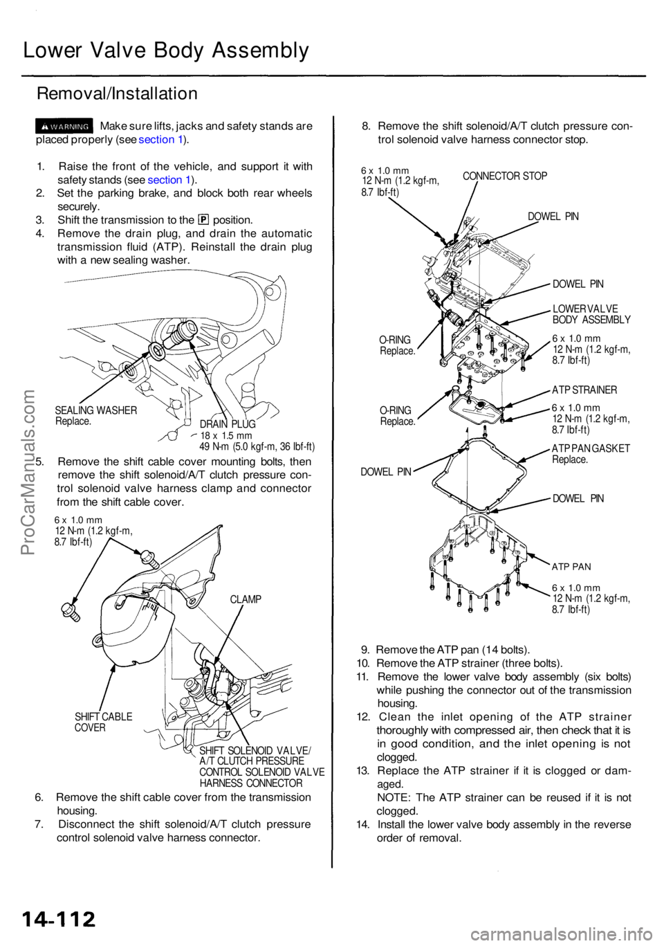
Make sur e lifts , jack s an d safet y stand s ar e
place d properl y (se e sectio n 1 ).
1 . Rais e th e fron t o f th e vehicle , an d suppor t i t wit h
safet y stand s (se e sectio n 1 ).
2 . Se t th e parkin g brake , an d bloc k bot h rea r wheel s
securely .
3. Shif t th e transmissio n to th e position .
4 . Remov e th e drai n plug , an d drai n th e automati c
transmissio n flui d (ATP) . Reinstal l th e drai n plu g
wit h a ne w sealin g washer . 8
. Remov e th e shif t solenoid/A/ T clutc h pressur e con -
tro l solenoi d valv e harnes s connecto r stop .
6 x 1. 0 m m12 N- m (1. 2 kgf-m ,
8. 7 Ibf-ft ) CONNECTO
R STO P
O-RIN G
Replace .
O-RING
Replace .
DOWE L PI N DOWE
L PI N
DOWE L PI N
ATP PA N
6 x 1. 0 m m12 N- m (1. 2 kgf-m ,
8. 7 Ibf-ft )
9. Remov e th e AT P pa n (1 4 bolts) .
10 . Remov e th e AT P straine r (thre e bolts) .
11 . Remov e th e lowe r valv e bod y assembl y (si x bolts )
whil e pushin g th e connecto r ou t o f th e transmissio n
housing .
12 . Clea n th e inle t openin g o f th e AT P straine r
thoroughly wit h compresse d air , the n chec k tha t i t i s
in goo d condition , an d th e inle t openin g i s no t
clogged .
13 . Replac e th e AT P straine r i f i t i s clogge d o r dam -
aged.
NOTE : Th e AT P straine r ca n b e reuse d i f i t i s no t
clogged .
14. Instal l th e lowe r valv e bod y assembl y in th e revers e
orde r o f removal .
SEALING WASHE R
Replace .
5. Remov e th e shif t cabl e cove r mountin g bolts , the n
remov e th e shif t solenoid/A/ T clutc h pressur e con -
tro l solenoi d valv e harnes s clam p an d connecto r
fro m th e shif t cabl e cover .
DRAIN PLU G18 x 1. 5 m m49 N- m (5. 0 kgf-m , 3 6 Ibf-ft ) DOWE
L PI N
LOWE R VALV E
BOD Y ASSEMBL Y
6 x 1. 0 m m12 N- m (1. 2 kgf-m ,
8. 7 Ibf-ft )
AT P STRAINE R
6 x 1. 0 m m12 N- m (1. 2 kgf-m ,
8. 7 Ibf-ft )
AT P PA N GASKE T
Replace .
6 x 1. 0 m m12 N- m (1. 2 kgf-m ,
8. 7 Ibf-ft )
SHIF T CABL E
COVER
SHIFT SOLENOI D VALVE /
A/ T CLUTC H PRESSUR E
CONTRO L SOLENOI D VALV E
HARNES S CONNECTO R
CLAM
P
6. Remov e th e shif t cabl e cove r fro m th e transmissio n
housing .
7 . Disconnec t th e shif t solenoid/A/ T clutc h pressur e
contro l solenoi d valv e harnes s connector .
ProCarManuals.com
Page 909 of 1954
Link Adjustmen t
• Mak e sur e lifts , jack s an d safet y stand s ar e place d
properl y (se e sectio n 1 ).
• Appl y parkin g
brake, and bloc k rea r wheel s s o vehi -
cle wil l no t rol l of f stand s an d fal l o n yo u whil e work -
ing unde r it .
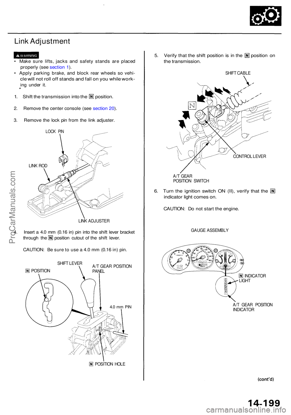
1. Shif t the transmissio n into the position .
2. Remov e th e cente r consol e (se e sectio n 20 ).
3 . Remov e th e loc k pi n fro m th e lin k adjuster .
LINK RO D
LINK ADJUSTE R
4. Inser t a 4. 0 m m (0.1 6 in ) pi n int o th e shif t leve r bracke t
through th e positio n cutou t o f th e shif t lever .
CAUTION : B e sur e t o us e a 4. 0 m m (0.1 6 in ) pin .
SHIF T LEVE R
POSITIO NA/T GEA R POSITIO N
PANE L
POSITIO N HOL E
5. Verif y tha t th e shif t positio n is i n th e positio n o n
the transmission .
SHIFT CABL E
CONTRO L LEVE R
A/ T GEA R
POSITIO N SWITC H
6. Tur n th e ignitio n switc h O N (II) , verif y tha t th e
indicato r ligh t come s on .
CAUTION : D o no t star t th e engine .
GAUGE ASSEMBL Y
INDICATOR
LIGH T
A/ T GEA R POSITIO N
INDICATO R
LOCK PI N
4.0 m m PI N
ProCarManuals.com
Page 911 of 1954
Shift Cabl e
Replacemen t
• Mak e sur e lifts , jacks , an d safet y stand s ar e place d
properl y (se e sectio n
1).
• Appl y th e parkin g brake , an d bloc k th e rea r wheel s s o
th e vehicl e wil l no t rol l of f th e stand s an d fal l o n yo u
whil e workin g unde r it .
1 . Rais e th e fron t o f th e vehicle , an d suppor t i t wit h
safet y stand s (se e sectio n
1).
2 . Se t th e parkin g brake , an d bloc k bot h rea r wheel s
securely .
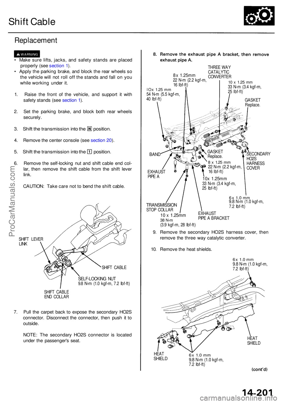
3. Shif t th e transmissio n int o th e position .
4. Remov e th e cente r consol e (se e sectio n 20 ).
5 . Shif t th e transmissio n int o th e position .
6. Remov e th e self-lockin g nu t an d shif t cabl e en d col -
lar , the n remov e th e shif t cabl e fro m th e shif t leve r
link .
CAUTION : Tak e car e no t t o ben d th e shif t cable .
SHIFT LEVE RLINK
SHIF T CABL E
SELF-LOCKIN G NU T9.8 N- m (1. 0 kgf-m , 7.2 Ibf-ft )
SHIFT CABL E
EN D COLLA R
7. Pul l th e carpe t bac k t o expos e th e secondar y HO2 S
connector . Disconnec t th e connector , the n pus h i t t o
outside .
NOTE : Th e secondar y HO2 S connecto r i s locate d
unde r th e passenger' s seat .
BAND
EXHAUS TPIPE A
TRANSMISSIO NSTOP COLLA R
10 x 1.25m m38 N- m(3.9 kgf-m , 28 Ibf-ft )
SECONDAR Y
HO2 S
HARNES S
COVE R
6x 1. 0 m m9.8 N- m (1. 0 kgf-m ,7.2 Ibf-ft )
EXHAUS T
PIP E A BRACKE T
9. Remov e th e secondar y HO2 S harnes s cover , the n
remov e th e thre e wa y catalyti c converter .
10 . Remov e th e hea t shields .
6x 1. 0 m m9.8 N- m (1. 0 kgf-m ,7.2 Ibf-ft )
HEATSHIEL D6x 1.0 m m9.8 N- m (1. 0 kgf-m ,7.2 Ibf-ft )
HEAT
SHIEL D
8x 1.25m m22 N- m (2. 2 kgf-m ,16 Ibf-ft )
THRE E WA Y
CATALYTI C
CONVERTE R
10 x 1.2 5 mm33 N- m (3. 4 kgf-m ,25 Ibf-ft )
GASKE TReplace .
lOx 1.2 5 mm54 N- m (5. 5 kgf-m ,40 Ibf-ft )
GASKE T
Replace .
8 x 1.2 5 mm22 N- m (2. 2 kgf-m ,16 Ibf-ft )
10x 1.25m m33 N- m (3. 4 kgf-m ,25 Ibf-ft )
ProCarManuals.com
Page 916 of 1954
Differential Assembly
Removal
Make sur e jack s an d safet y stand s ar e place d properly ,
an d hois t bracket s ar e attache d to correc t position s o n
th e engine .
Appl y parkin g brak e an d bloc k rea r wheel s s o th e
vehicl e wil l no t rol l of f stand s an d fal l o n yo u whil e
workin g unde r it .
CAUTION : Us e fende r cover s to avoi d damagin g painte d
surfaces .
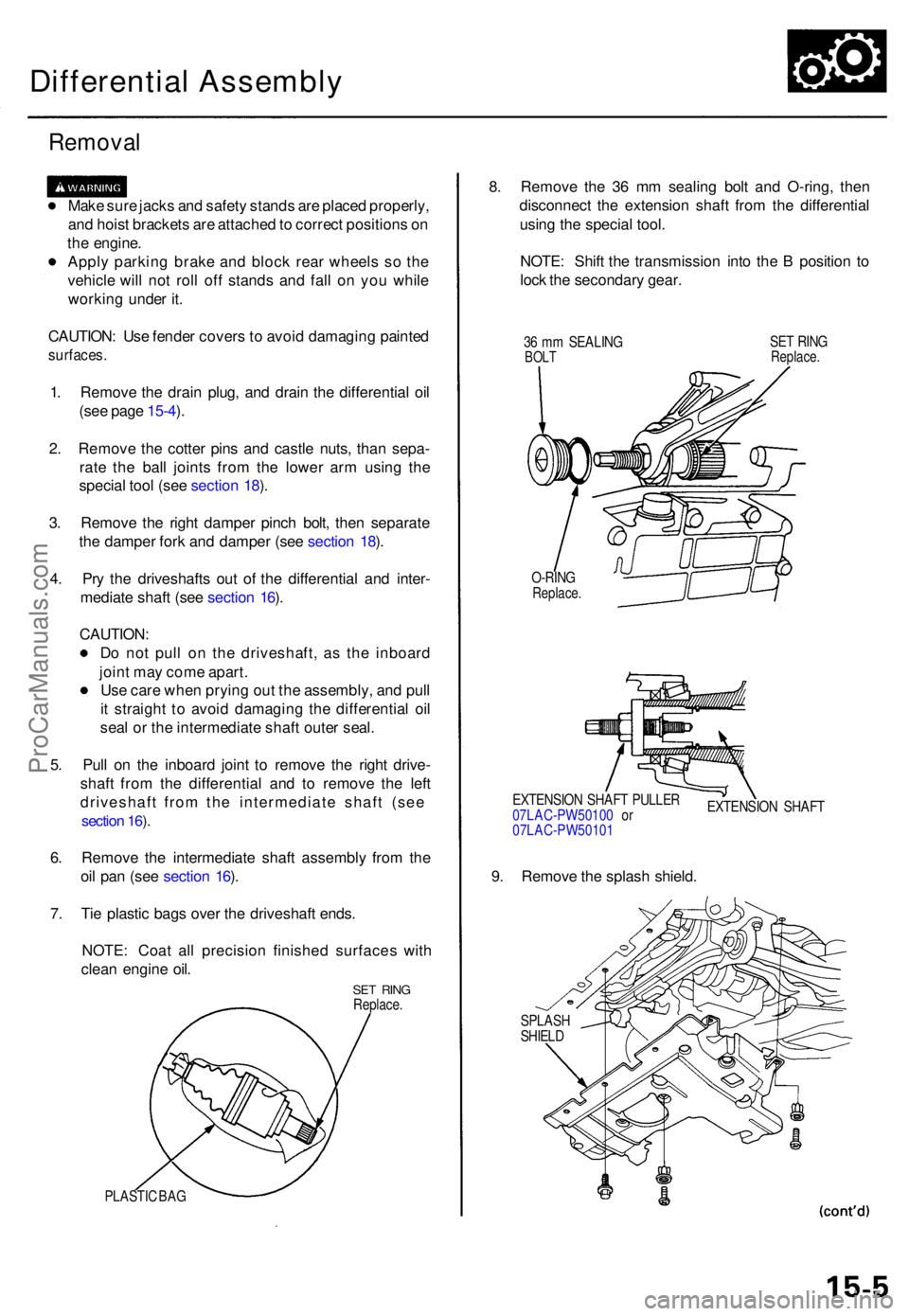
1. Remov e th e drai n plug , an d drai n th e differentia l oi l
(se e pag e 15-4 ).
2 . Remov e th e cotte r pin s an d castl e nuts , tha n sepa -
rat e th e bal l joint s fro m th e lowe r ar m usin g th e
specia l too l (se e sectio n 18 ).
3 . Remov e th e righ t dampe r pinc h bolt , the n separat e
th e dampe r for k an d dampe r (se e sectio n 18 ).
4 . Pr y th e driveshaft s ou t o f th e differentia l an d inter -
mediat e shaf t (se e sectio n 16 ).
CAUTION :
D o no t pul l o n th e driveshaft , a s th e inboar d
join t ma y com e apart .
Us e car e whe n pryin g ou t th e assembly , an d pul l
i t straigh t t o avoi d damagin g th e differentia l oi l
sea l o r th e intermediat e shaf t oute r seal .
5 . Pul l o n th e inboar d join t t o remov e th e righ t drive -
shaf t fro m th e differentia l an d t o remov e th e lef t
driveshaft from the intermediate shaft (see
section 16 ).
6 . Remov e th e intermediat e shaf t assembl y fro m th e
oi l pa n (se e sectio n 16 ).
7 . Ti e plasti c bag s ove r th e driveshaf t ends .
NOTE : Coa t al l precisio n finishe d surface s wit h
clea n engin e oil .
SE T RIN GReplace .
PLASTIC BA G
8. Remov e th e 3 6 m m sealin g bol t an d O-ring , the n
disconnec t th e extensio n shaf t fro m th e differentia l
usin g th e specia l tool .
NOTE : Shif t th e transmissio n int o th e B positio n t o
loc k th e secondar y gear .
36 m m SEALIN GBOLTSET RIN GReplace .
O-RINGReplace .
EXTENSIO N SHAF T PULLE R
07LAC-PW5010 0 o r
07LAC-PW5010 1 EXTENSIO
N SHAF T
9. Remov e th e splas h shield .
SPLAS HSHIELD
ProCarManuals.com
Page 945 of 1954
Driveshafts
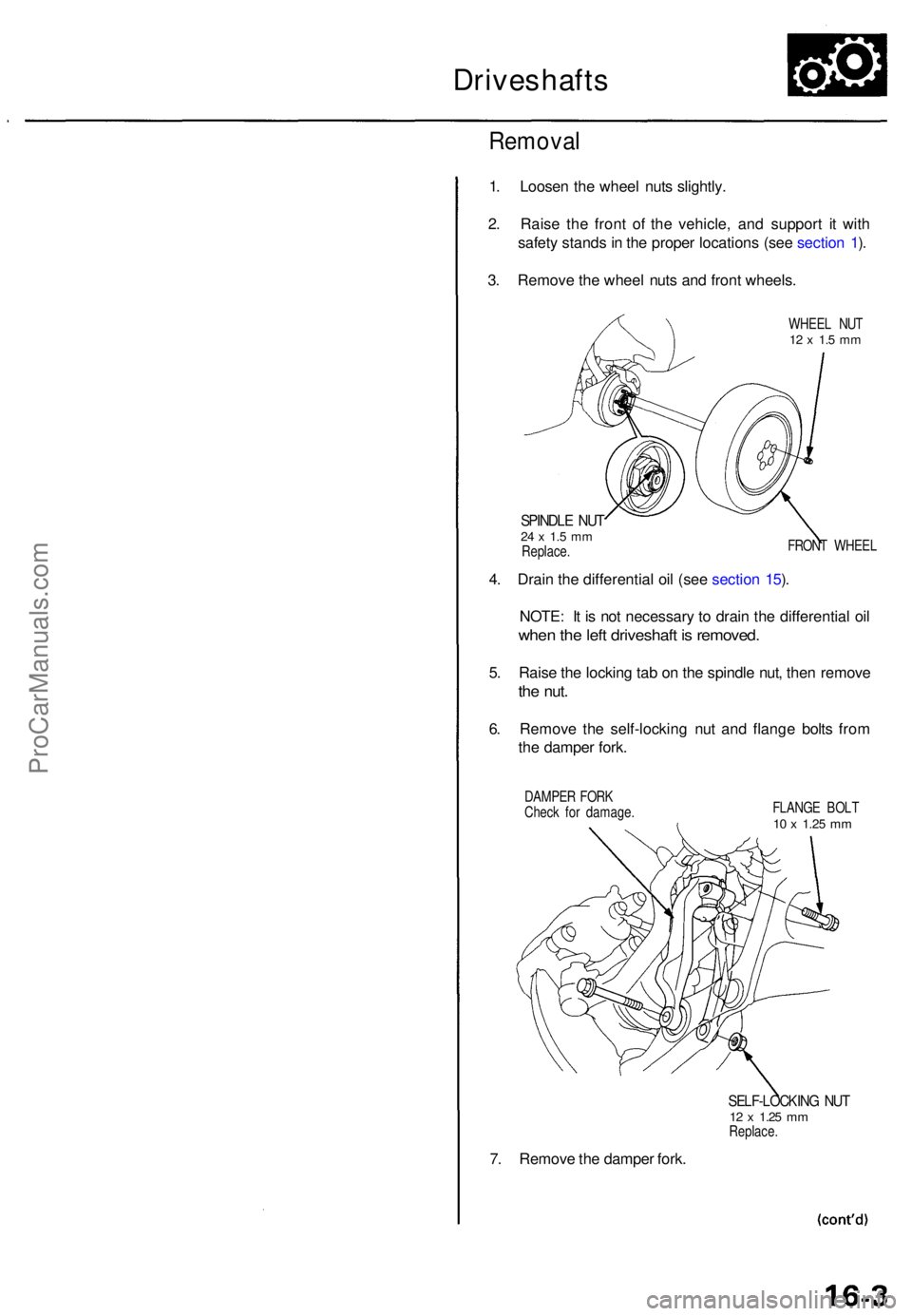
Removal
1. Loose n th e whee l nut s slightly .
2 . Rais e th e fron t o f th e vehicle , an d suppor t i t wit h
safet y stand s in th e prope r location s (se e sectio n 1 ).
3 . Remov e th e whee l nut s an d fron t wheels .
WHEEL NU T12 x 1. 5 m m
SPINDL E NU T24 x 1. 5 m mReplace . FRON
T WHEE L
4. Drai n th e differentia l oi l (se e sectio n 15 ).
NOTE : I t i s no t necessar y t o drai n th e differentia l oi l
whe n th e lef t driveshaf t i s removed .
5. Rais e th e lockin g ta b o n th e spindl e nut , the n remov e
the nut .
6. Remov e th e self-lockin g nu t an d flang e bolt s fro m
th e dampe r fork .
DAMPE R FOR K
Chec k fo r damage . FLANG
E BOL T
10 x 1.2 5 mm
7. Remov e th e dampe r fork .
SELF-LOCKIN G NU T12 x 1.2 5 mmReplace .
ProCarManuals.com
Page 959 of 1954
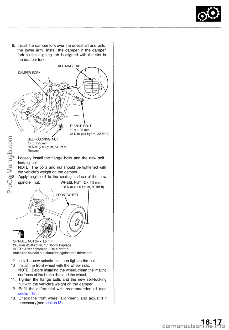
6. Instal l th e dampe r for k ove r th e driveshaf t an d ont o
the lowe r arm . Instal l th e dampe r i n th e dampe r
for k s o th e alignin g ta b i s aligne d wit h th e slo t i n
th e dampe r fork .
ALIGNIN G TAB
DAMPE R FOR K
FLANG E BOL T10 x 1.2 5 mm43 N- m (4. 4 kgf-m , 3 2 Ibf-ft )
SELF-LOCKIN G NU T12 x 1.2 5 mm69 N- m (7. 0 kgf-m , 5 1 Ibf-ft )Replace .
7. Loosel y instal l th e flang e bolt s an d th e ne w self -
lockin g nut .
NOTE : Th e bolt s an d nu t shoul d b e tightene d wit h
th e vehicle' s weigh t o n th e damper .
8 . Appl y engin e oi l t o th e seatin g surfac e o f th e ne w
spindl e nut . WHEE L NU T 1 2 x 1. 5 m m
108 N- m (11. 0 kgf-m , 8 0 Ibf-ft )
SPINDL E NU T 2 4 x 1. 5 m m245 N- m (25. 0 kgf-m , 18 1 Ibf-ft ) Replace .NOTE: Afte r tightening , us e a drif t t o
stak e th e spindl e nu t shoulde r agains t th e driveshaft .
9. Instal l a ne w spindl e nut , the n tighte n th e nut .
10 . Instal l th e fron t whee l wit h th e whee l nuts .
NOTE : Befor e installin g th e wheel , clea n th e matin g
surface s o f th e brak e dis c an d th e wheel .
11 . Tighten the flang e bolt s an d th e ne w self-lockin g
nu t wit h th e vehicle' s weigh t o n th e damper .
12 . Refil l th e differentia l with recommende d oi l (se e
sectio n 15 ).
13 . Chec k th e fron t whee l alignment , an d adjus t i t i f
necessar y (se e sectio n 18 ).
FRON T WHEE L
ProCarManuals.com
Page 968 of 1954
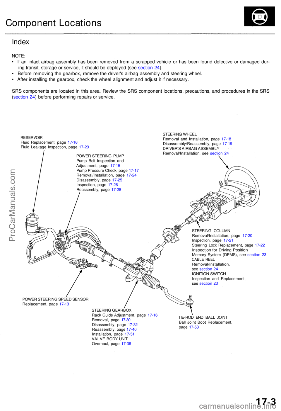
STEERING WHEE L
Remova l an d Installation , pag e 17-1 8
Disassembly/Reassembly , pag e 17-1 9
DRIVER' S AIRBA G ASSEMBL Y
Removal/Installation , se e sectio n 2 4
Inde x
NOTE :
• I f a n intac t airba g assembl y ha s bee n remove d fro m a scrappe d vehicl e o r ha s bee n foun d defectiv e o r damage d dur -
in g transit , storag e o r service , i t shoul d b e deploye d (se e sectio n 24 ).
• Befor e removin g th e gearbox , remov e th e driver' s airba g assembl y an d steerin g wheel .
• Afte r installin g th e gearbox , chec k th e whee l alignmen t an d adjus t i t i f necessary .
SR S component s ar e locate d in thi s area . Revie w th e SR S componen t locations , precautions , an d procedure s i n th e SR S
( sectio n 24 ) befor e performin g repair s o r service .
Componen t Location s
RESERVOI RFluid Replacement , pag e 17-1 6
Flui d Leakag e Inspection , pag e 17-2 3
POWE R STEERIN G PUM P
Pum p Bel t Inspectio n an d
Adjustment , pag e 17-1 5
Pum p Pressur e Check , pag e 17-1 7
Removal/Installation , pag e 17-2 4
Disassembly , pag e 17-2 5
Inspection , pag e 17-2 6
Reassembly , pag e 17-2 8
POWE R STEERIN G SPEE D SENSO R
Replacement , pag e 17-1 3
STEERIN G GEARBO XRack Guid e Adjustment , pag e 17-1 6
Removal , pag e 17-3 0
Disassembly , pag e 17-3 2
Reassembly , pag e 17-4 0
Installation , pag e 17-5 1
VALV E BOD Y UNI T
Overhaul , pag e 17-3 6 TIE-RO
D EN D BAL L JOIN T
Bal l Join t Boo t Replacement ,
pag e 17-5 3
STEERIN
G COLUM N
Removal/Installation , pag e 17-2 0
Inspection , pag e 17-2 1
Steerin g Loc k Replacement , pag e 17-2 2
Inspectio n fo r Drivin g Positio nMemory Syste m (DPMS), see sectio n 2 3CABL E REE LRemoval/Installation ,
se e sectio n 2 4
IGNITIO N SWITC HInspectio n an d Replacement ,
se e sectio n 2 3
ProCarManuals.com
Page 977 of 1954

Inspection an d Adjustmen t
Steering Operatio n
Place th e fron t wheel s i n th e straigh t ahea d position ,
an d measur e th e distanc e th e steerin g whee l ca n b e
turne d withou t movin g th e fron t wheels .
ROTATIONA L PLAY : 0 - 1 0 m m (0 - 0.3 9 in )
If th e pla y exceed s th e servic e limit, perfor m rack guid e
adjustmen t (se e pag e 17-16 ).
I f th e pla y i s stil l excessiv e afte r rac k guid e adjustment ,
inspec t th e steerin g linkag e an d gearbo x (se e pag e
17-14 ).
Powe r Assis t Chec k wit h Vehicl e
Parked
1. Chec k th e powe r steerin g flui d leve l (se e pag e 17-16 )
an d pum p bel t tensio n (se e pag e 17-15 ).
2 . Star t th e engine , allo w it t o idle , an d tur n th e steer -
in g whee l fro m lock-to-loc k severa l time s t o war m
up th e fluid .
3. Attac h a sprin g scal e to th e steerin g wheel . Wit h th e
engin e idlin g an d th e vehicl e o n a clean , dr y floor ,
pul l th e scal e a s shown . Rotat e th e steerin g whee l
mor e tha n 9 0 degre e angl e b y pullin g th e sprin g
scale . Rea d th e figur e o n th e sprin g scal e whil e th e
steerin g whee l i s in motion .
4 . Th e scal e shoul d rea d n o mor e the n 2 5 N (2. 6 kgf ,
5. 7 Ibf) . I f i t read s more , g o o n to ste p 5 .
5 . Sto p th e engine . Disconnec t th e senso r inle t hos e
fro m th e powe r steerin g spee d sensor , an d plu g th e
hos e an d th e senso r fittin g a s shown .
6 . Star t th e engine , an d le t i t idle .
• I f th e readin g i s stil l mor e tha n 2 5 N (2. 6 kgf , 5. 7
Ibf ) th e powe r steerin g spee d senso r i s OK .
Proble m is i n th e pum p o r valv e bod y uni t (se e
Genera l Troubleshooting) .
• I f th e readin g is no w 2 5 N (2. 6 kgf , 5. 7 Ibf ) o r less ,
powe r steerin g spee d senso r leak s internally .
Replac e th e senso r (se e pag e 17-13 ).
ProCarManuals.com