1996 ACURA RL KA9 wheel
[x] Cancel search: wheelPage 1053 of 1954
Major adjustment :
Adjust th e parkin g brak e sho e lining-to-dru m clearanc e
with th e adjuste r i n th e dru m o f eac h rea r wheel .
NOTE : Mak e sur e th e parkin g brak e lining s ar e no t wor n
beyon d th e servic e limi t (se e pag e 19-23 ).
If eithe r lining is wor n beyon d the limit , both brak e
shoe s mus t b e replaced .
CAUTION : Afte r replacin g th e linings , mak e sur e yo u
driv e th e vehicl e fo r "break-in " purposes . Refe r t o pag e
19-2 7 fo r th e linin g surfac e brake-i n procedure .
1 . Rais e th e rea r wheel s of f th e ground , an d suppor t
th e vehicl e o n safet y stands .
Bloc k th e fron t wheel s befor e jackin g
u p th e rea r o f th e vehicle .
2 . Remov e th e rea r wheels .
3 . Remov e th e rea r consol e en d cover .
4 . Releas e th e parkin g brak e pedal , an d bac k of f th e
adjustin g nu t i n th e equalizer .
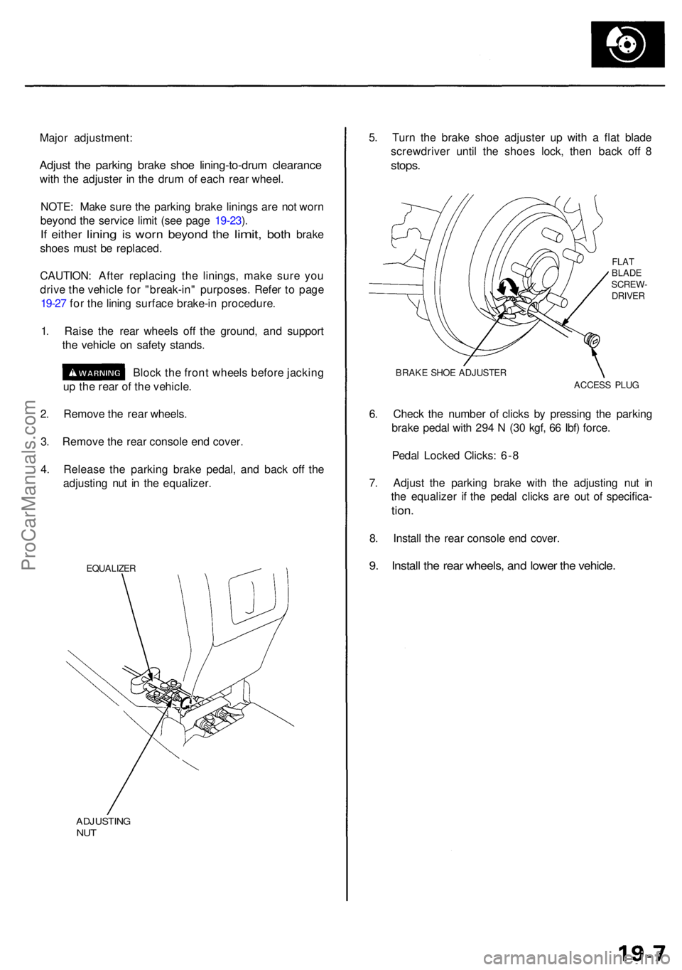
EQUALIZE R
ADJUSTIN GNUT
5. Tur n th e brak e sho e adjuste r u p wit h a fla t blad e
screwdrive r unti l th e shoe s lock , the n bac k of f 8
stops .
FLATBLAD E
SCREW -
DRIVE R
BRAK E SHO E ADJUSTE R
ACCESS PLU G
6. Chec k th e numbe r o f click s b y pressin g th e parkin g
brak e peda l wit h 29 4 N (3 0 kgf , 6 6 Ibf ) force .
Peda l Locke d Clicks : 6- 8
7 . Adjus t th e parkin g brak e wit h th e adjustin g nu t i n
th e equalize r i f th e peda l click s ar e ou t o f specifica -
tion.
8. Instal l th e rea r consol e en d cover .
9. Instal l th e rea r wheels , an d lowe r th e vehicle .
ProCarManuals.com
Page 1054 of 1954
Inspection and Adjustment
Bleeding
CAUTION:
• Always use Genuine Honda DOT 3 Brake Fluid. Using
a non-Honda brake fluid can cause corrosion and
decrease the life of the system.
• Make sure no dirt or other foreign matter is allowed
to contaminate the brake fluid.
• Do not spill brake fluid on the vehicle, it may damage
the paint; if brake fluid does contact the paint, wash
it off immediately with water.
NOTE: The reservoir on the master cylinder must be at
the MAX (upper) level mark at the start of the bleeding
procedure and checked after bleeding each brake
caliper. Add fluid as required.
1. Make sure the brake fluid level in the reservoir is at
the MAX (upper) level line.
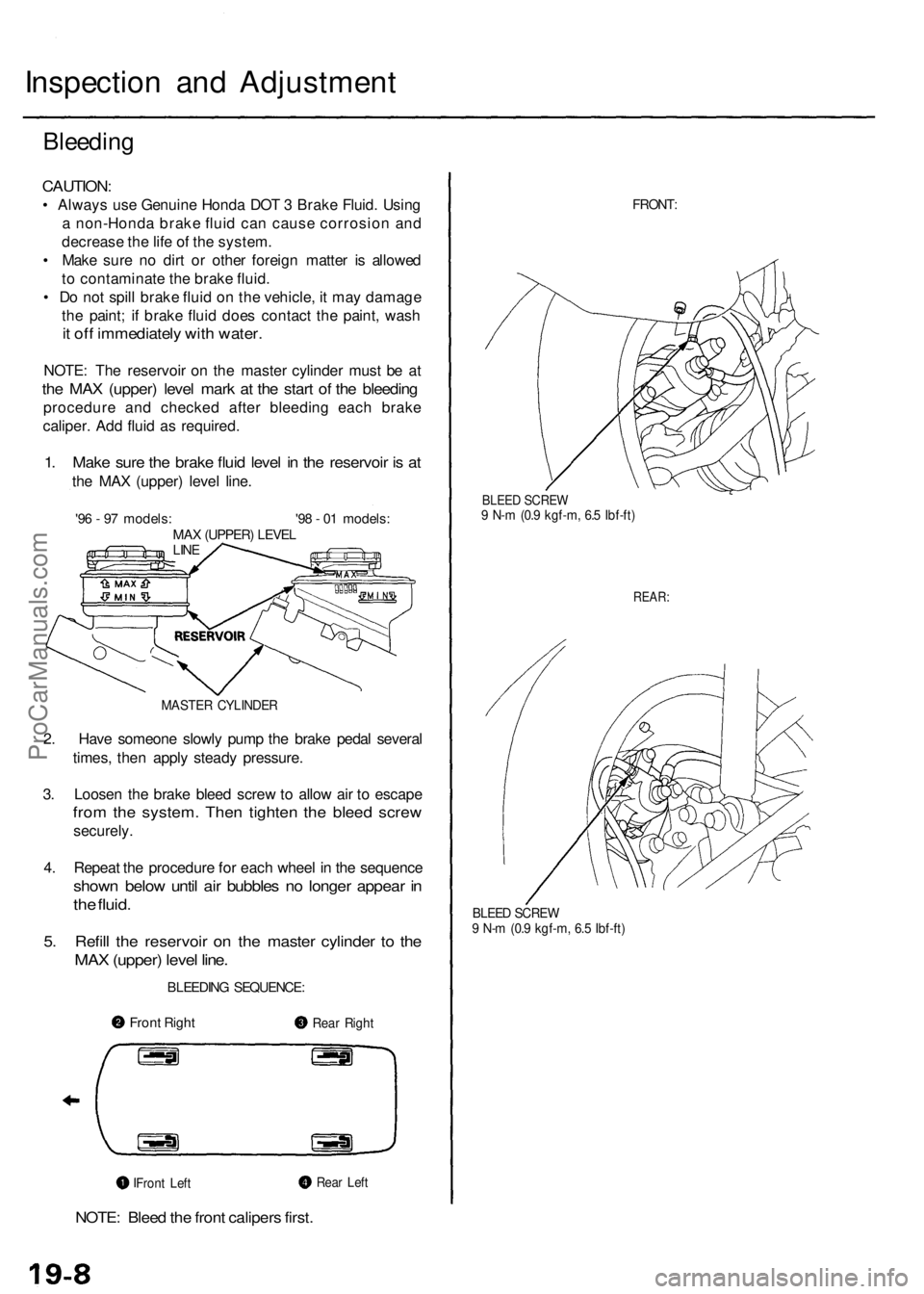
'96 - 97 models: '98 - 01 models:
MAX (UPPER) LEVEL
LINE
MASTER CYLINDER
2. Have someone slowly pump the brake pedal several
times, then apply steady pressure.
3. Loosen the brake bleed screw to allow air to escape
from the system. Then tighten the bleed screw
securely.
4. Repeat the procedure for each wheel in the sequence
shown below until air bubbles no longer appear in
the fluid.
5. Refill the reservoir on the master cylinder to the
MAX (upper) level line.
BLEEDING SEQUENCE:
NOTE: Bleed the front calipers first.
FRONT:
BLEED SCREW
9 N-m (0.9 kgf-m, 6.5 Ibf-ft)
REAR:
BLEED SCREW
9 N-m (0.9 kgf-m, 6.5 Ibf-ft)
Front Right
Rear Right
Rear Left
Front LeftProCarManuals.com
Page 1056 of 1954
Front Brak e Pad s
Inspectio n an d Replacemen t
• Neve r us e a n ai r hos e o r dr y brus h t o clea n brake
assemblies .
• Us e a n OSHA-approve d vacuu m cleane r t o avoi d
breathin g brak e dust .
1 . Loose n th e fron t whee l nut s slightly , the n rais e th e
vehicle , an d suppor t i t o n safet y stands . Remov e
th e fron t wheels .
2 . Remov e th e brak e hos e bracke t fro m th e knuckle .
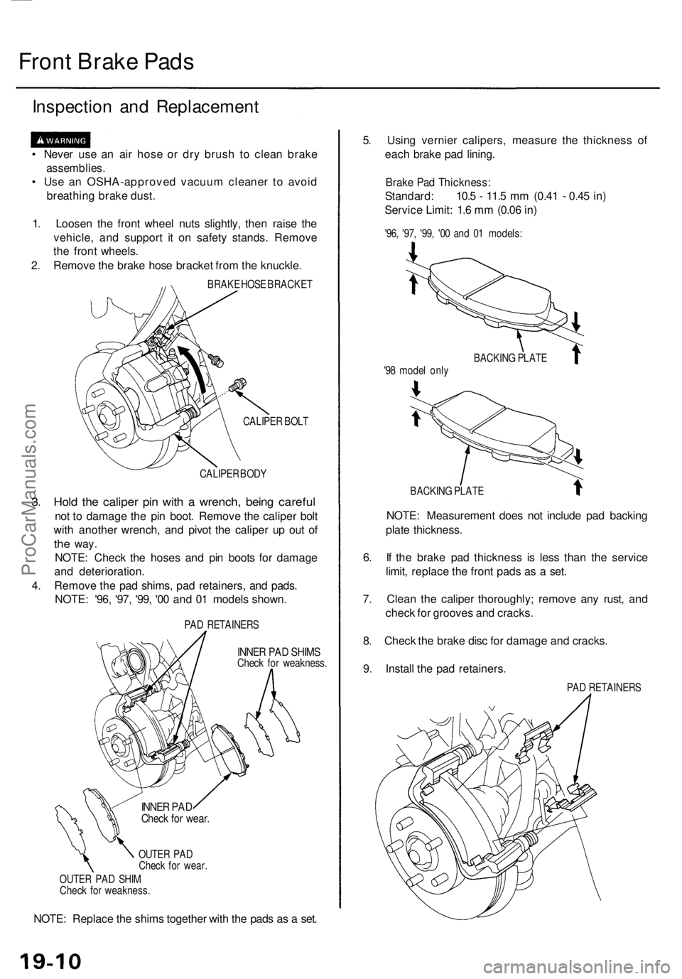
BRAKE HOS E BRACKE T
CALIPE R BOL T
CALIPE R BOD Y
3. Hol d th e calipe r pi n wit h a wrench , bein g carefu l
not t o damag e th e pi n boot . Remov e th e calipe r bol t
wit h anothe r wrench , an d pivo t th e calipe r u p ou t o f
the way .
NOTE : Chec k th e hose s an d pi n boot s fo r damag e
an d deterioration .
4 . Remov e th e pa d shims , pa d retainers , an d pads .
NOTE : '96 , '97 , '99 , '0 0 an d 0 1 model s shown .
PAD RETAINER S
INNER PA D SHIM SCheck fo r weakness .
OUTE R PA D
Chec k fo r wear .
OUTE R PA D SHI M
Chec k fo r weakness .
NOTE: Replac e th e shim s togethe r wit h th e pad s a s a set . 5
. Usin g vernie r calipers , measur e th e thicknes s of
eac h brak e pa d lining .
Brake Pa d Thickness :
Standard: 10. 5 - 11. 5 m m (0.4 1 - 0.4 5 in )
Servic e Limit : 1. 6 m m (0.0 6 in )
'96 , '97 , '99 , '0 0 an d 0 1 models :
BACKIN G PLAT E
NOTE: Measuremen t doe s no t includ e pa d backin g
plat e thickness .
6 . I f th e brak e pa d thicknes s i s les s tha n th e servic e
limit , replac e th e fron t pad s a s a set .
7 . Clea n th e calipe r thoroughly ; remov e an y rust , an d
chec k fo r groove s an d cracks .
8 . Chec k th e brak e dis c fo r damag e an d cracks .
9 . Instal l th e pa d retainers .
PAD RETAINER S
BACKIN
G PLAT E
'9 8 mode l onl y
INNE R PA DChec k fo r wear .
ProCarManuals.com
Page 1058 of 1954
Front Brak e Dis c
Disc Runou t Inspectio n
1. Loose n th e fron t whee l nut s slightly , the n rais e th e
vehicle , an d mak e sur e i t i s securel y supported .
Remov e th e fron t wheels .
2 . Remov e th e brak e pad s (se e pag e 19-10 ).
3 .
4 .
5 .
Inspec t th e dis c surfac e fo r damag e an d cracks .
Clean th e dis c thoroughly , an d remov e al l rust .
Us e whee l nut s an d suitabl e plai n washer s t o hol d
th e dis c securel y agains t th e hub , the n moun t a dia l
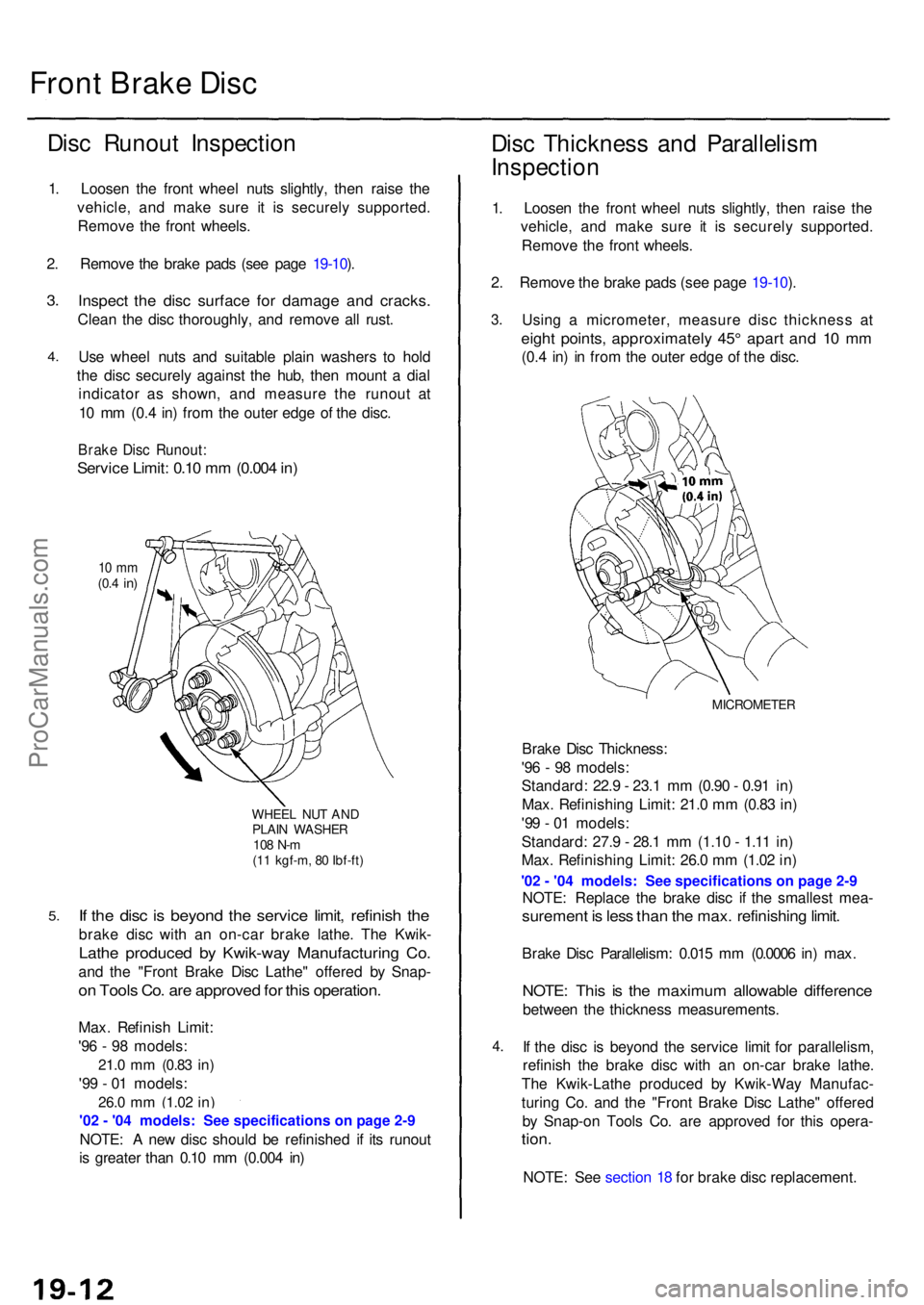
indicato r a s shown , an d measur e th e runou t a t
1 0 m m (0. 4 in ) fro m th e oute r edg e o f th e disc .
Brak e Dis c Runout :
Service Limit : 0.1 0 m m (0.00 4 in )
10 m m(0.4 in )
WHEE L NU T AN DPLAI N WASHE R108 N- m(11 kgf-m , 8 0 Ibf-ft )
If th e dis c i s beyon d th e servic e limit , refinis h th e
brak e dis c wit h a n on-ca r brak e lathe . Th e Kwik -
Lathe produce d b y Kwik-wa y Manufacturin g Co .
and th e "Fron t Brak e Dis c Lathe " offere d b y Snap -
on Tool s Co . ar e approve d fo r thi s operation .
Max. Refinis h Limit :
'9 6 - 9 8 models :
21.0 mm (0.8 3 in)
'99 - 0 1 models :
26.0 mm (1.0 2 in)
NOTE : A ne w dis c shoul d b e refinishe d i f it s runou t
i s greate r tha n 0.1 0 m m (0.00 4 in )
Dis c Thicknes s an d Parallelis m
Inspectio n
1. Loose n th e fron t whee l nut s slightly , the n rais e th e
vehicle , an d mak e sur e i t i s securel y supported .
Remov e th e fron t wheels .
2 . Remov e th e brak e pad s (se e pag e 19-10 ).
3 .
4.
Usin g a micrometer , measur e dis c thicknes s a t
eigh t points , approximatel y 45 ° apar t an d 1 0 m m
(0.4 in ) i n fro m th e oute r edg e o f th e disc .
MICROMETE R
Brake Dis c Thickness :
'9 6 - 9 8 models :
Standard : 22. 9 - 23. 1 m m (0.9 0 - 0.9 1 in )
Max . Refinishin g Limit : 21. 0 m m (0.8 3 in )
'9 9 - 0 1 models :
Standard : 27. 9 - 28. 1 m m (1.1 0 - 1.1 1 in )
Max . Refinishin g Limit : 26. 0 m m (1.0 2 in )
NOTE : Replac e th e brak e dis c i f th e smalles t mea -
suremen t i s les s tha n th e max . refinishin g limit .
Brak e Dis c Parallelism : 0.01 5 m m (0.000 6 in ) max .
NOTE : Thi s i s th e maximu m allowabl e differenc e
between th e thicknes s measurements .
I f th e dis c i s beyon d th e servic e limi t fo r parallelism ,
refinis h th e brak e dis c wit h a n on-ca r brak e lathe .
Th e Kwik-Lath e produce d b y Kwik-Wa y Manufac -
turin g Co . an d th e "Fron t Brak e Dis c Lathe " offere d
b y Snap-o n Tool s Co . ar e approve d fo r thi s opera -
tion.
NOTE : Se e sectio n 1 8 fo r brak e dis c replacement .
ProCarManuals.com
Page 1065 of 1954
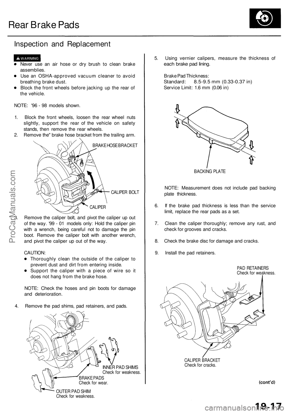
Rear Brake Pads
Inspection and Replacement
Never use an air hose or dry brush to clean brake
assemblies.
Use an OSHA-approved vacuum cleaner to avoid
breathing brake dust.
Block the front wheels before jacking up the rear of
the vehicle.
NOTE: '96 - 98 models shown.
1. Block the front wheels, loosen the rear wheel nuts
slightly, support the rear of the vehicle on safety
stands, then remove the rear wheels.
2. Remove the" brake hose bracket from the trailing arm.
BRAKE HOSE BRACKET
CALIPER BOLT
3.
CALIPER
Remove the caliper bolt, and pivot the caliper up out
of the way. '99 - 01 models only: Hold the caliper pin
with a wrench, being careful not to damage the pin
boot. Remove the caliper bolt with another wrench,
and pivot the caliper up out of the way.
CAUTION:
Thoroughly clean the outside of the caliper to
prevent dust and dirt from entering inside.
Support the caliper with a piece of wire so it
does not hang from the brake hose.
NOTE: Check the hoses and pin boots for damage
and deterioration.
4. Remove the pad shims, pad retainers, and pads.
INNER PAD SHIMS
Check for weakness.
BRAKE PADS
Check for wear.
OUTER PAD SHIM
Check for weakness.
5. Using vernier calipers, measure the thickness of
each brake pad lining.
Brake Pad Thickness:
Standard: 8.5-9.5 mm (0.33-0.37 in)
Service Limit: 1.6 mm (0.06 in)
BACKING PLATE
NOTE: Measurement does not include pad backing
plate thickness.
6. If the brake pad thickness is less than the service
limit, replace the rear pads as a set.
7. Clean the caliper thoroughly; remove any rust, and
check for grooves and cracks.
8. Check the brake disc for damage and cracks.
9. Install the pad retainers.
PAD RETAINERS
Check for weakness.
CALIPER BRACKET
Check for cracks.ProCarManuals.com
Page 1067 of 1954
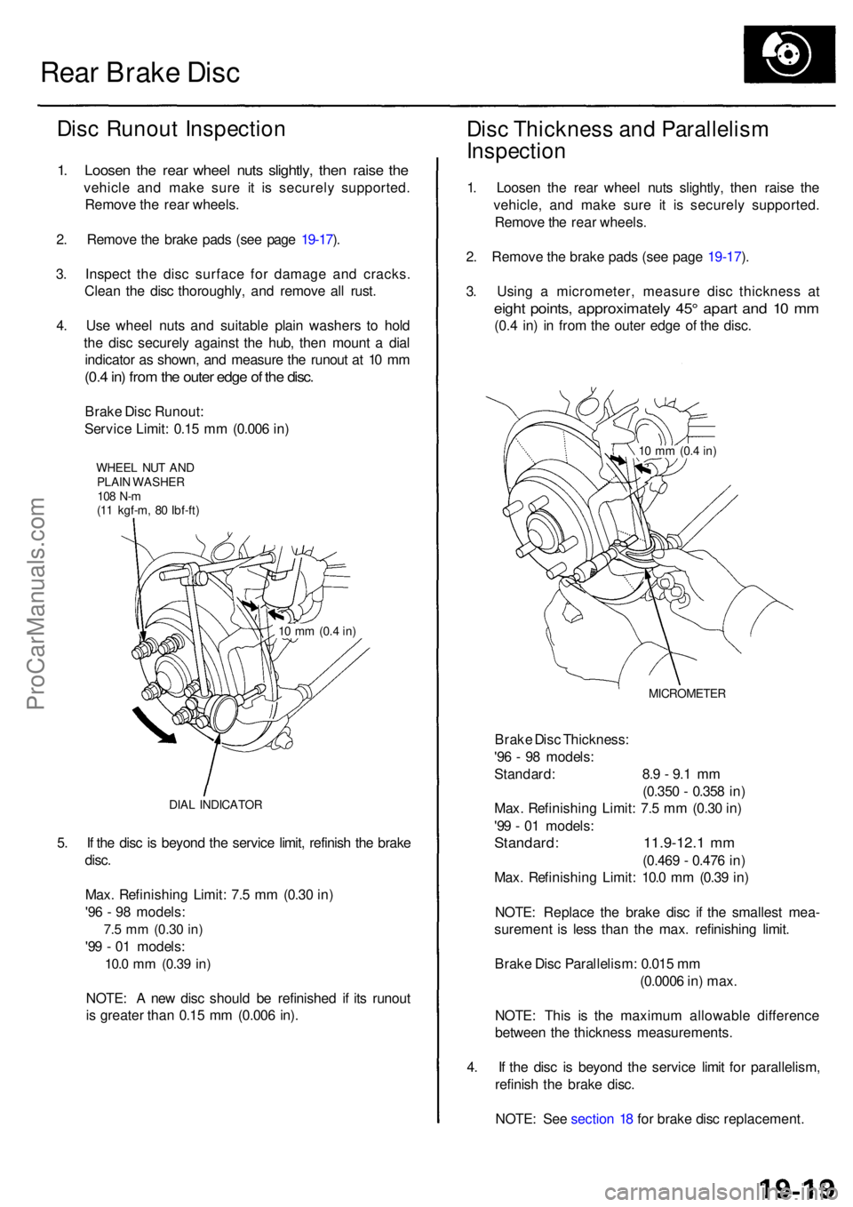
Rear Brak e Dis c
Disc Runou t Inspectio n
1. Loose n th e rea r whee l nut s slightly , the n rais e th e
vehicl e an d mak e sur e i t i s securel y supported .
Remov e th e rea r wheels .
2 . Remov e th e brak e pad s (se e pag e 19-17 ).
3 . Inspec t th e dis c surfac e fo r damag e an d cracks .
Clea n th e dis c thoroughly , an d remov e al l rust .
4 . Us e whee l nut s an d suitabl e plai n washer s t o hol d
th e dis c securel y agains t th e hub , the n moun t a dia l
indicato r a s shown , an d measur e th e runou t a t 1 0 m m
(0.4 in ) fro m th e oute r edg e o f th e disc .
Brak e Dis c Runout :
Servic e Limit : 0.1 5 m m (0.00 6 in )
WHEE L NU T AN DPLAI N WASHE R108 N- m(11 kgf-m , 8 0 Ibf-ft )
DIA L INDICATO R
5. I f th e dis c i s beyon d th e servic e limit , refinis h th e brak e
disc .
Max . Refinishin g Limit : 7. 5 m m (0.3 0 in )
'9 6 - 9 8 models :
7.5 m m (0.3 0 in)
'99 - 0 1 models :
10.0 mm (0.3 9 in)
NOTE : A ne w dis c shoul d b e refinishe d i f it s runou t
i s greate r tha n 0.1 5 m m (0.00 6 in) .
Dis c Thicknes s an d Parallelis m
Inspectio n
1. Loose n th e rea r whee l nut s slightly , the n rais e th e
vehicle , an d mak e sur e i t i s securel y supported .
Remov e th e rea r wheels .
2 . Remov e th e brak e pad s (se e pag e 19-17 ).
3 . Usin g a micrometer , measur e dis c thicknes s a t
eigh t points , approximatel y 45 ° apar t an d 1 0 m m
(0.4 in ) i n fro m th e oute r edg e o f th e disc .
MICROMETE R
Brake Dis c Thickness :
'9 6 - 9 8 models :
Standard : 8. 9 - 9. 1 m m
(0.35 0 - 0.35 8 in )
Max . Refinishin g Limit : 7. 5 m m (0.3 0 in )
'9 9 - 0 1 models :
Standard : 11.9-12. 1 m m
(0.46 9 - 0.47 6 in )
Max . Refinishin g Limit : 10. 0 m m (0.3 9 in )
NOTE : Replac e th e brak e dis c i f th e smalles t mea -
suremen t i s les s tha n th e max . refinishin g limit .
Brak e Dis c Parallelism : 0.01 5 m m
(0.000 6 in ) max .
NOTE : Thi s i s th e maximu m allowabl e differenc e
betwee n th e thicknes s measurements .
4 . I f th e dis c i s beyon d th e servic e limi t fo r parallelism ,
refinis h th e brak e disc .
NOTE : Se e sectio n 1 8 fo r brak e dis c replacement .
10 m m (0. 4 in)
10 m m (0. 4 in)
ProCarManuals.com
Page 1070 of 1954
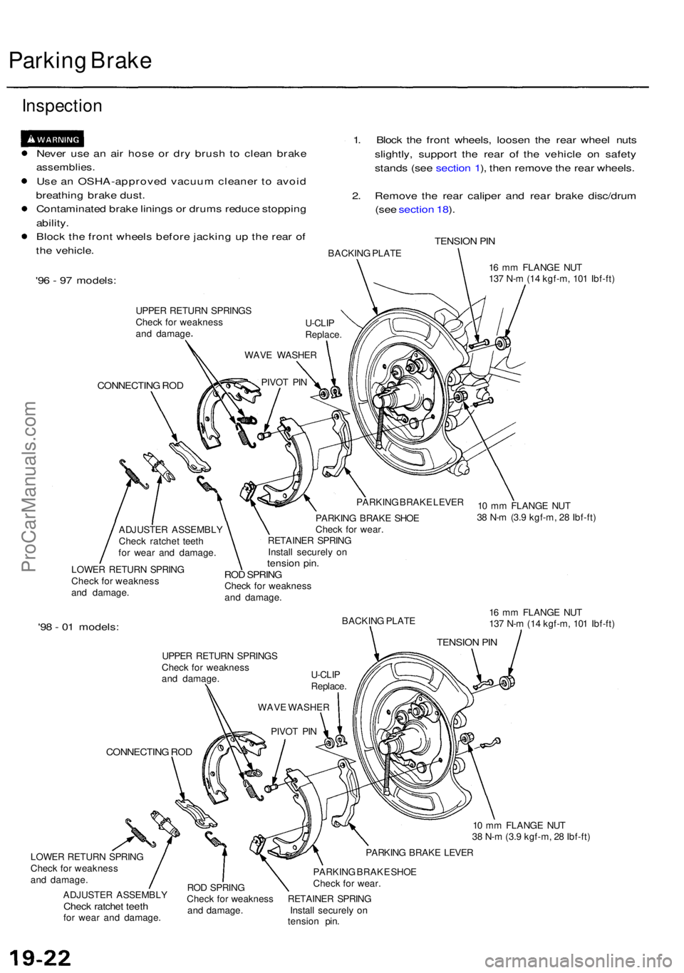
Parking Brak e
Inspectio n
Never us e a n ai r hos e o r dr y brus h t o clea n brak e
assemblies .
Use a n OSHA-approve d vacuu m cleane r t o avoi d
breathin g brak e dust .
Contaminate d brak e lining s o r drum s reduc e stoppin g
ability .
Bloc k th e fron t wheel s befor e jackin g u p th e rea r o f
th e vehicle . 1
. Bloc k th e fron t wheels , loose n th e rea r whee l nut s
slightly , suppor t th e rea r of the vehicl e o n safet y
stand s (se e sectio n 1 ), the n remov e th e rea r wheels .
2 . Remov e th e rea r calipe r an d rea r brak e disc/dru m
(se e sectio n 18 ).
TENSIO N PI NBACKIN G PLAT E
'96 - 9 7 models :
UPPER RETUR N SPRING S
Chec k fo r weaknes s
an d damag e
CONNECTIN G RO D
16 m m FLANG E NU T
13 7 N- m (1 4 kgf-m , 10 1 Ibf-ft )
ADJUSTE R ASSEMBL Y
Chec k ratche t teet h
fo r wea r an d damage .
LOWE R RETUR N SPRIN G
Chec k fo r weaknes s
an d damage . PARKIN
G BRAK E LEVE R
PARKIN G BRAK E SHO E
Chec k fo r wear .
RETAINE R SPRIN G
Instal l securel y o n
tensio n pin .ROD SPRIN GCheck fo r weaknes s
an d damage .
'98 - 0 1 models :BACKIN G PLAT E
UPPE R RETUR N SPRING S
Chec k fo r weaknes s
an d damage .
CONNECTIN G RO D
LOWE R RETUR N SPRIN G
Chec k fo r weaknes s
an d damage .
ADJUSTE R ASSEMBL Y
Check ratche t teet hfor wea r an d damage . 1
6 m m FLANG E NU T
13 7 N- m (1 4 kgf-m , 10 1 Ibf-ft )
1 0 m m FLANG E NU T
3 8 N- m (3. 9 kgf-m , 2 8 Ibf-ft )
PARKIN G BRAK E LEVE R
RO D SPRIN G PARKIN
G BRAK E SHO E
Chec k fo r wear .
Chec k fo r weaknes s RETAINE R SPRIN G
an d damage . Instal l securel y o n
tensio n pin .
PIVO
T PI N
WAV
E WASHE R
U-CLI
P
Replace .
WAV
E WASHE R
PIVO T PI NU-CLI
P
Replace .
TENSION PI N
10 m m FLANG E NU T
3 8 N- m (3. 9 kgf-m , 2 8 Ibf-ft )
ProCarManuals.com
Page 1081 of 1954
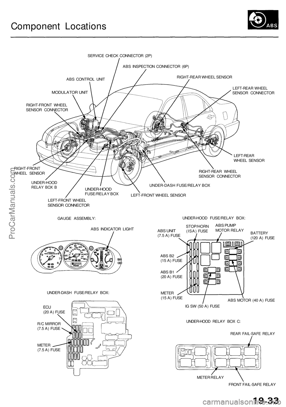
Component Locations
ABS CONTROL UNIT
MODULATOR UNIT
SERVICE CHECK CONNECTOR (2P)
ABS INSPECTION CONNECTOR (6P)
RIGHT-REAR WHEEL SENSOR
RIGHT-FRONT WHEEL
SENSOR CONNECTOR
RIGHT-FRONT
WHEEL SENSOR
LEFT-REAR WHEEL
SENSOR CONNECTOR
LEFT-REAR
WHEEL SENSOR
RIGHT-REAR WHEEL
SENSOR CONNECTOR
UNDER-HOOD
RELAY BOX B
UNDER-HOOD
FUSE/RELAY BOX
UNDER-DASH FUSE/RELAY BOX
LEFT-FRONT WHEEL SENSOR
LEFT-FRONT WHEEL
SENSOR CONNECTOR
GAUGE ASSEMBLY:
ABS INDICATOR LIGHT
UNDER-DASH FUSE/RELAY BOX:
METER
(7.5 A) FUSE
ABS B2
(15 A) FUSE
ABS B1
(20 A) FUSE
METER
(15 A) FUSE
BATTERY
(120 A) FUSE
ABS MOTOR (40 A) FUSE
IG SW (50 A) FUSE
UNDER-HOOD RELAY BOX C:
REAR FAIL-SAFE RELAY
METER RELAY
FRONT FAIL-SAFE RELAY
ABS
UNIT
(7.5 A) FUSE
STOP/HORN
(ISA) FUSE
ABS PUMP
MOTOR RELAY
UNDER-HOOD FUSE/RELAY BOX:
ECU
(20 A) FUSE
R/C MIRROR
(7.5 A) FUSEProCarManuals.com