1996 ACURA RL KA9 suspension
[x] Cancel search: suspensionPage 1 of 1954

General Info
Specifications
Maintenance
*Engine Electrical
Engine
Cooling
Fuel and Emissions
*TransaxleSteering
Suspension
*Brakes (Including ABS,
TCS and VSA)
*Body
*Heating, Ventilation and Air Conditioning
*Body Electrical
*Restraints
1996±0 4 3.5RL Main Menu
As sections w/ * include SRS components,
special precautions are required when servicing.
ProCarManuals.com
Page 1026 of 1954
Wheel Alignment
Caster
NOTE: For proper inspection/adjustment of the wheel
alignment, check and adjust the following before check-
ing the alignment:
Check that the suspension is not modified.
Check the tire size and tire pressure.
Check the runout of the wheels and tires.
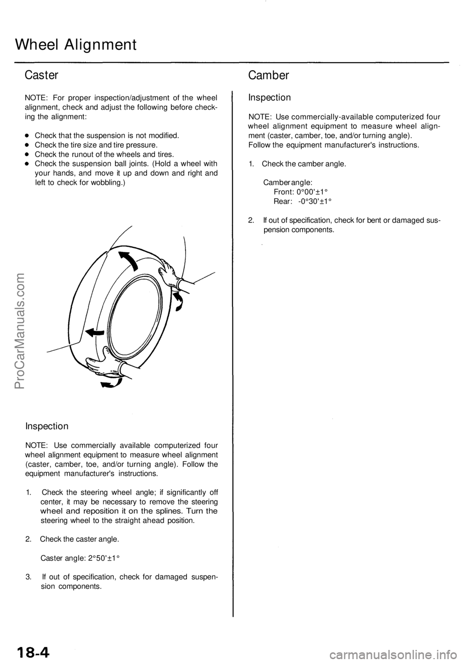
Check the suspension ball joints. (Hold a wheel with
your hands, and move it up and down and right and
left to check for wobbling.)
Inspection
NOTE: Use commercially available computerized four
wheel alignment equipment to measure wheel alignment
(caster, camber, toe, and/or turning angle). Follow the
equipment manufacturer's instructions.
1. Check the steering wheel angle; if significantly off
center, it may be necessary to remove the steering
wheel and reposition it on the splines. Turn the
steering wheel to the straight ahead position.
2. Check the caster angle.
Caster angle: 2°50'±1°
3. If out of specification, check for damaged suspen-
sion components.
Camber
Inspection
NOTE: Use commercially-available computerized four
wheel alignment equipment to measure wheel align-
ment (caster, camber, toe, and/or turning angle).
Follow the equipment manufacturer's instructions.
1. Check the camber angle.
Camber angle:
Front: 0°00'±1°
Rear: -0°30'±1°
2. If out of specification, check for bent or damaged sus-
pension components.ProCarManuals.com
Page 1037 of 1954
Suspension Arms Removal/Inspection
CAUTION:
• Replace the self-locking nuts after removal.
• Be careful not to damage the ball joint boot.
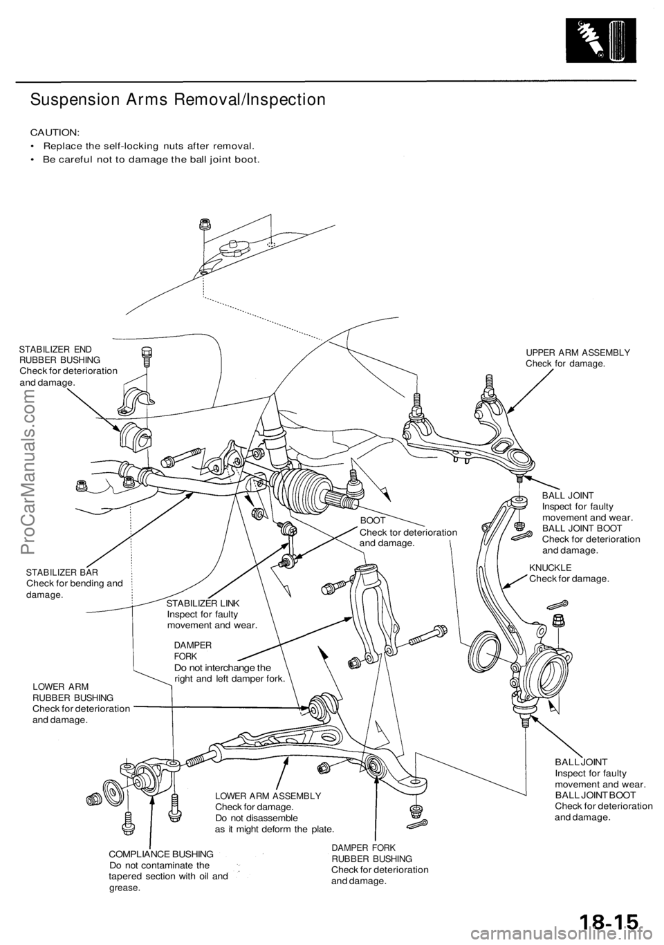
STABILIZER END
RUBBER BUSHING
Check for deterioration
and damage.
UPPER ARM ASSEMBLY
Check for damage.
STABILIZER BAR
Check for bending and
damage.
BALL JOINT
Inspect for faulty
movement and wear.
BALL JOINT BOOT
Check for deterioration
and damage.
KNUCKLE
Check for damage.
LOWER ARM
RUBBER BUSHING
Check for deterioration
and damage.
BALL JOINT
Inspect for faulty
movement and wear.
BALL JOINT BOOT
Check for deterioration
and damage.
COMPLIANCE BUSHING
Do not contaminate the
tapered section with oil and
grease.
DAMPER FORK
RUBBER BUSHING
Check for deterioration
and damage.
LOWER ARM ASSEMBLY
Check for damage.
Do not disassemble
as it might deform the plate.
DAMPER
FORK
Do not interchange the
right and left damper fork.
STABILIZER LINK
Inspect for faulty
movement and wear.
BOOT
Check tor deterioration
and damage.ProCarManuals.com
Page 1038 of 1954
Front Suspension
Suspension Arms Installation
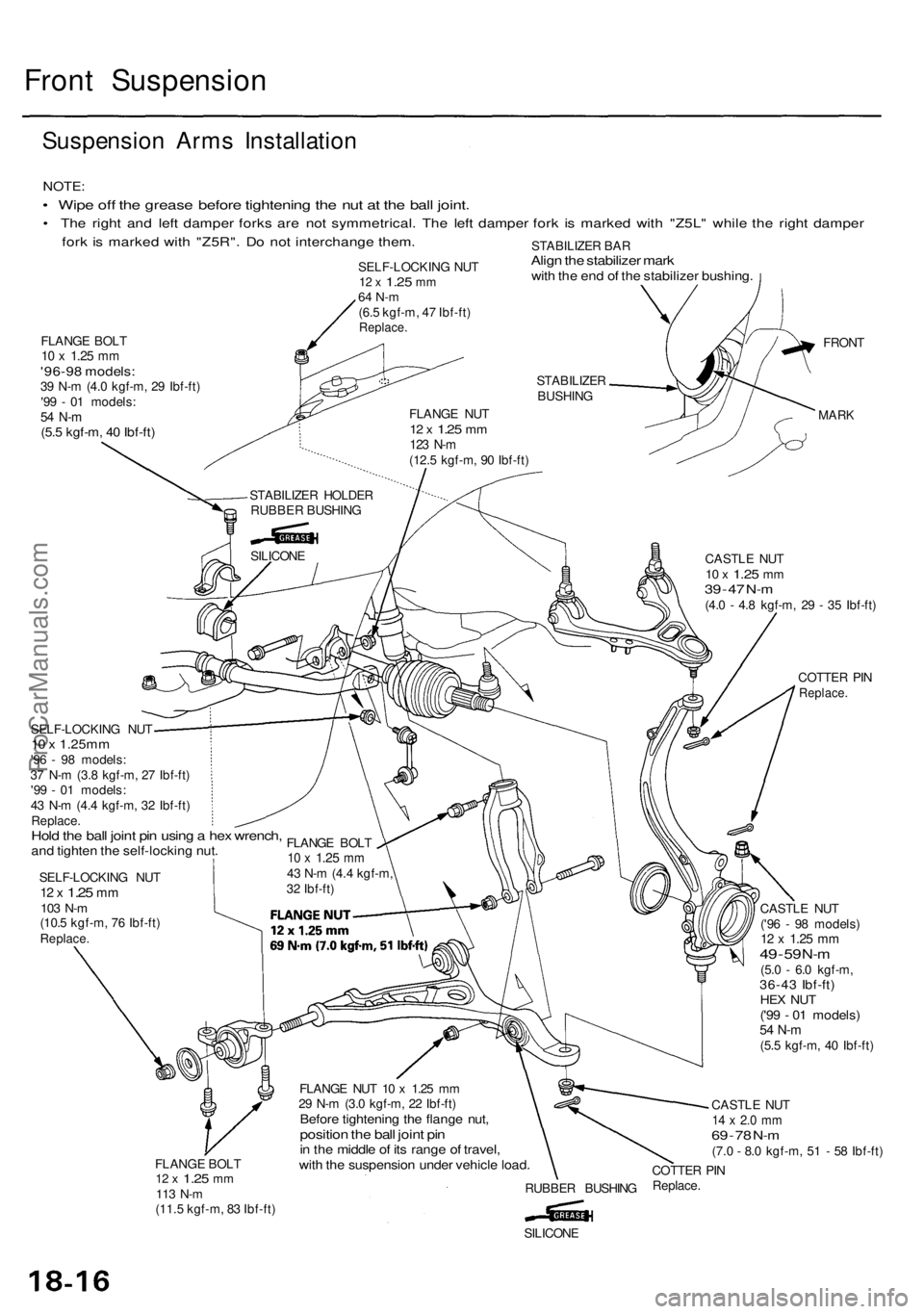
NOTE:
• Wipe off the grease before tightening the nut at the ball joint.
• The right and left damper forks are not symmetrical. The left damper fork is marked with "Z5L" while the right damper
fork is marked with "Z5R". Do not interchange them.
STABILIZER BAR
Align the stabilizer mark
with the end of the stabilizer bushing.
FLANGE BOLT
10 x
1.25
mm
'96-98 models:
39 N-m (4.0 kgf-m, 29 Ibf-ft)
'99 - 01 models:
54 N-m
(5.5 kgf-m, 40 Ibf-ft)
CASTLE NUT
10 x
1.25
mm
39 - 47
N-m
(4.0 - 4.8 kgf-m, 29 - 35 Ibf-ft)
COTTER PIN
Replace.
FRONT
MARK
SELF-LOCKING NUT
10 x 1.25mm
'96 - 98 models:
37 N-m (3.8 kgf-m, 27 Ibf-ft)
'99 - 01 models:
43 N-m (4.4 kgf-m, 32 Ibf-ft)
Replace.
Hold the ball joint pin using a hex wrench,
and tighten the self-locking nut.
SELF-LOCKING NUT
12 x
1.25
mm
103 N-m
(10.5 kgf-m, 76 Ibf-ft)
Replace.
FLANGE BOLT
12 x
1.25
mm
113 N-m
(11.5 kgf-m, 83 Ibf-ft)
FLANGE NUT 10 x 1.25 mm
29 N-m (3.0 kgf-m, 22 Ibf-ft)
Before tightening the flange nut,
position the ball joint pin
in the middle of its range of travel,
with the suspension under vehicle load.
RUBBER BUSHING
CASTLE NUT
('96 - 98 models)
12 x
1.25
mm
49
-
59
N-m
(5.0 - 6.0 kgf-m,
36-43 Ibf-ft)
HEX NUT
('99 - 01 models)
54 N-m
(5.5 kgf-m, 40 Ibf-ft)
CASTLE NUT
14 x 2.0 mm
69 - 78
N-m
(7.0 - 8.0 kgf-m, 51 - 58 Ibf-ft)
COTTER PIN
Replace.
SILICONE
SELF-LOCKING NUT
12 x
1.25
mm
64 N-m
(6.5 kgf-m, 47 Ibf-ft)
Replace.
STABILIZER
BUSHING
FLANGE NUT
12 x
1.25
mm
123 N-m
(12.5 kgf-m, 90 Ibf-ft)
STABILIZER HOLDER
RUBBER BUSHING
SILICONE
FLANGE BOLT
10 x
1.25
mm
43 N-m (4.4 kgf-m,
32 Ibf-ft)ProCarManuals.com
Page 1043 of 1954
Suspension Arm s Removal/Inspectio n
CAUTION:
• Replac e th e self-lockin g nut s afte r removal .
• B e carefu l no t t o damag e th e bal l join t boot .
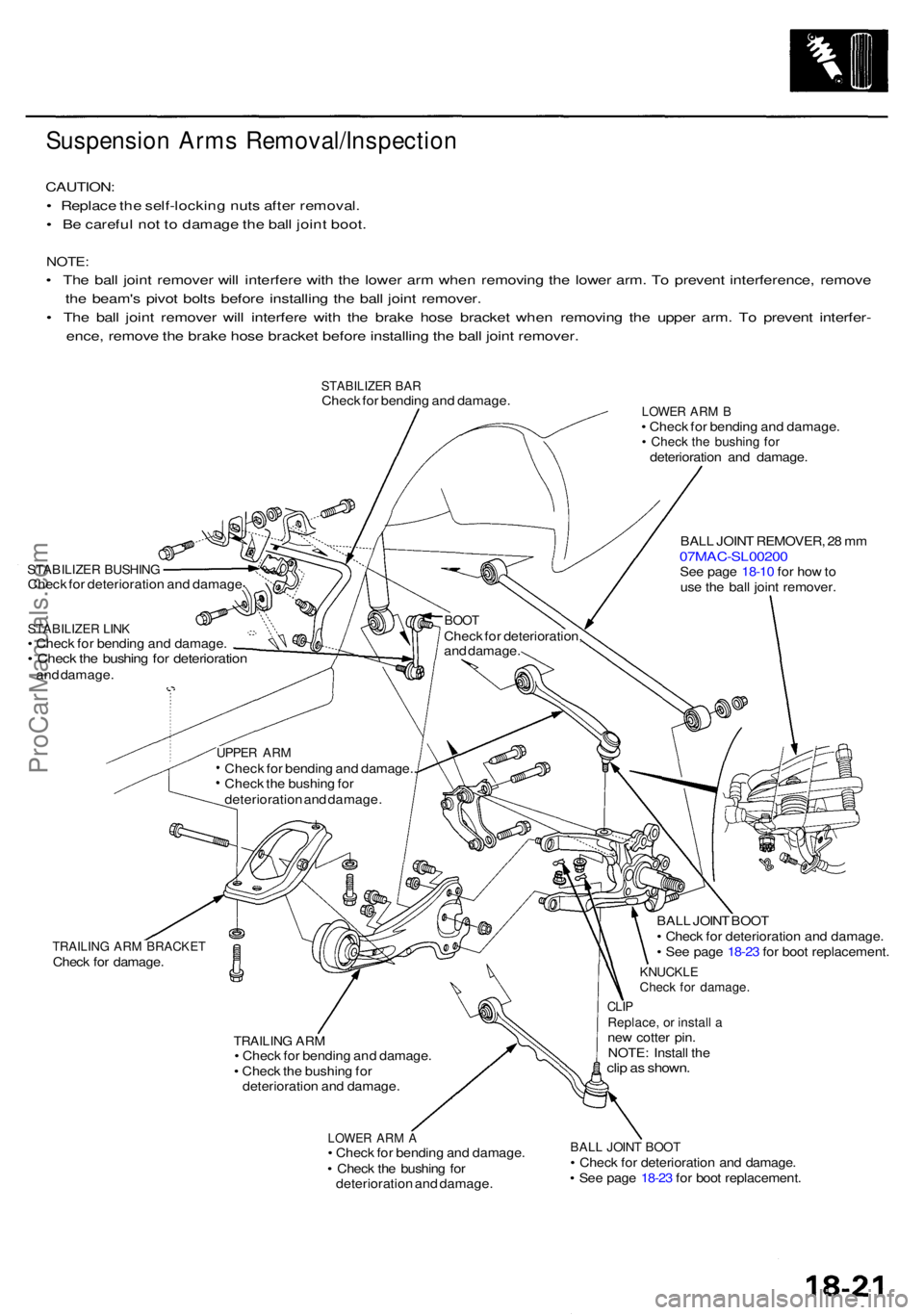
NOTE :
• Th e bal l join t remove r wil l interfer e wit h th e lowe r ar m whe n removin g th e lowe r arm . T o preven t interference , remov e
th e beam' s pivo t bolt s befor e installin g th e bal l join t remover .
• Th e bal l join t remove r wil l interfer e wit h th e brak e hos e bracke t whe n removin g th e uppe r arm . T o preven t interfer -
ence , remov e th e brak e hos e bracke t befor e installin g th e bal l join t remover .
STABILIZE R BA RChec k fo r bendin g an d damage .
STABILIZE R BUSHIN GCheck fo r deterioratio n an d damag e
STABILIZE R LIN K• Chec k fo r bendin g an d damage .• Chec k th e bushin g fo r deterioratio nand damage .
LOWER AR M B• Chec k fo r bendin g an d damage .• Chec k th e bushin g fo rdeterioratio n an d damage .
BAL L JOIN T REMOVER , 2 8 m m
07MAC-SL0020 0See pag e 18-1 0 fo r ho w to
us e th e bal l join t remover .
TRAILING AR M BRACKE TCheck fo r damage .
TRAILING AR M• Chec k fo r bendin g an d damage .
• Chec k th e bushin g fo r
deterioratio n an d damage .
LOWER AR M A• Chec k fo r bendin g an d damage .
• Chec k th e bushin g fo r
deterioratio n an d damage . BAL
L JOIN T BOO T
• Chec k fo r deterioratio n an d damage .
• Se e pag e 18-2 3 fo r boo t replacement .
KNUCKLECheck fo r damage .
CLIPReplace , o r instal l ane w cotte r pin .
NOTE : Instal l th e
clip a s shown .
BALL JOIN T BOO T• Chec k fo r deterioratio n an d damage .
• Se e pag e 18-2 3 fo r boo t replacement .
BOOTChec k fo r deterioration ,
an d damage .
UPPER AR MChec k fo r bendin g an d damage. .
Chec k th e bushin g fo r
deterioratio n an d damage .
ProCarManuals.com
Page 1044 of 1954
Rear Suspensio n
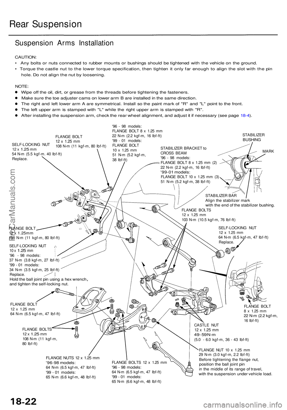
Suspension Arm s Installatio n
CAUTION:
• An y bolt s o r nut s connecte d to rubbe r mount s o r bushing s shoul d b e tightene d wit h th e vehicl e o n th e ground .
• Torqu e th e castl e nu t t o th e lowe r torqu e specification , the n tighte n it onl y fa r enoug h t o alig n th e slo t wit h th e pi n
hole . D o no t alig n th e nu t b y loosening .
NOTE:
Wipe of f th e oil , dirt , o r greas e fro m th e thread s befor e tightenin g th e fasteners .
Mak e sur e th e to e adjuste r cam s o n lowe r ar m B ar e installe d in th e sam e direction .
Th e righ t an d lef t lowe r ar m A ar e symmetrical . Instal l s o th e pain t mar k o f "R " an d "L " poin t t o th e front .
Th e lef t uppe r ar m is stampe d wit h "L " whil e th e righ t uppe r ar m is stampe d wit h "R" .
Afte r installin g th e suspensio n arm , chec k th e rea r whee l alignment , an d adjus t i t i f necessar y (se e pag e 18-4 ).
'9 6 - 9 8 models :
FLANG E BOL T 8 x 1.2 5 m m
2 2 N- m (2. 2 kgf-m , 1 6 Ibf-ft )
'9 9 - 0 1 models :
FLANG E BOL T
10 x 1.2 5 mm51 N- m (5. 2 kgf-m ,
3 8 Ibf-ft )
STABILIZE RBUSHING
STABILIZE R BRACKE T to
CROS S BEA M
'9 6 - 9 8 models :
FLANG E BOL T 8 x 1.25 m m (2 )
2 2 N- m (2. 2 kgf-m , 1 6 Ibf-ft )
'99-01 models :FLANGE BOL T 1 0 x 1.2 5 m m (3 )
5 1 N- m (5. 2 kgf-m , 3 8 Ibf-ft )
FLANG E BOL T
12 x 1.25m m108 N- m (1 1 kgf-m , 8 0 Ibf-ft )
SELF-LOCKIN G NU T ,- .
10 x 1.2 5 mm :'96 - 98 models :
3 7 N- m (3. 8 kgf-m , 2 7 Ibf-ft )
'99 - 0 1 models :34 N- m (3. 5 kgf-m , 2 5 Ibf-ft )
Replace .
Hold th e bal l join t pi n usin g a hex wrenc hand tighte n th e self-lockin g nut .
FLANG E BOL T12 x 1.2 5 mm64 N- m (6. 5 kgf-m , 4 7 Ibf-ft )
FLANG E BOLT S
12 x 1.2 5 mm108 N- m (1 1 kgf-m ,
8 0 Ibf-ft )
FLANG E NUT S 1 2 x 1.2 5 m m'96-9 8 models :64 N- m (6. 5 kgf-m , 4 7 Ibf-ft )'99 - 0 1 models :65 N- m (6. 6 kgf-m , 4 8 Ibf-ft ) STABILIZE
R BA R
Alig n th e stabilize r mar kwith th e en d o f th e stabilize r bushing .FLANGE BOLT S12 x 1.2 5 mm103 N- m (10. 5 kgf-m , 7 6 Ibf-ft )
SELF-LOCKIN G NU T
12 x 1.2 5 mm64 N- m (6. 5 kgf-m , 4 7 Ibf-ft )Replace .
MARK
FLANG E BOL T
8 x 1.2 5 mm22 N- m (2. 2 kgf-m ,16 Ibf-ft )
FLANG E BOLT S 1 2 x 1.2 5 m m
'96 - 9 8 models :64 N- m (6. 5 kgf-m , 4 7 Ibf-ft )'99 - 0 1 models :65 N- m (6. 6 kgf-m , 4 8 Ibf-ft ) CASTL
E NU T
12 x 1.2 5 mm49 - 5 9 N- m(5. 0 - 6. 0 kgf-m , 3 6 - 4 3 Ibf-ft )
FLANG E NU T 1 0 x 1.2 5 m m
2 9 N- m (3. 0 kgf-m , 2. 2 Ibf-ft )
Before tightenin g th e flang e nut ,positio n th e bal l join t pi nin th e middl e o f it s rang e o f travel ,with th e suspensio n unde r vehicl e load .
SELF-LOCKIN G NU T12 x 1.2 5 mm54 N- m (5. 5 kgf-m . 4 0 Ibf-ft )Replace .
FLANGE BOL T12 x 1.2 5 mm108 N- m (1 1 kgf-m , 8 0 Ibf-ft )
ProCarManuals.com
Page 1045 of 1954
Rear Dampe r
Do no t damag e th eslidin g surfac e o fthe bal l pi n wit hthe bearin g puller .
RETAINE R(Upper bal l join tonly)
BAL L PI N TAPERE D SECTIO N
4. Wip e th e greas e of f th e slidin g surfac e o f th e bal l
pin , pac k i t wit h fres h grease , an d instal l th e retaine r
(Uppe r bal l join t only) .
CAUTION :
• Kee p greas e of f th e boo t installatio n sectio n an d
th e tapere d sectio n o f th e bal l pin .
• D o no t allo w dust , dirt , o r othe r foreig n materi -
als to ente r th e boot .
5 . Instal l th e boo t i n th e groov e o f th e boo t installatio n
sectio n securely , the n blee d air .
6 . Adjus t th e specia l too l wit h th e adjustin g bol t unti l th e
en d o f th e too l align s wit h th e groov e o n th e boot .
Slid e th e se t rin g ove r th e too l an d int o position .
BALL JOIN T BOO T
CLI P GUID E
07GA G - SD4070 0 ADJUSTIN
G BOL TAdjust th e dept h b yturnin g th e bolt .
SET RIN G
BOO T
CAUTION : Afte r installin g th e boot , chec k th e bal l
pi n tapere d sectio n fo r greas e contamination , an d
wip e it i f necessary .
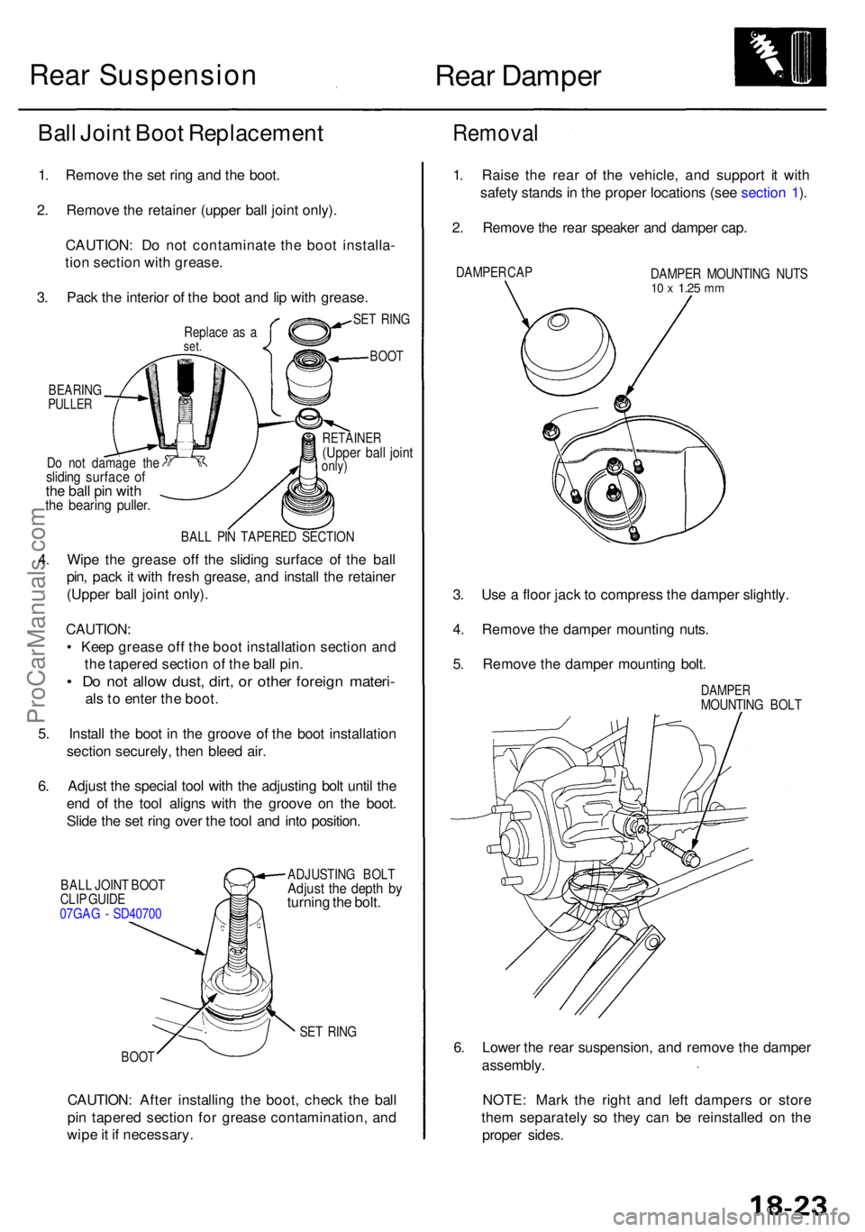
Removal
1. Rais e th e rea r o f th e vehicle , an d suppor t i t wit h
safet y stand s in th e prope r location s (se e sectio n 1 ).
2 . Remov e th e rea r speake r an d dampe r cap .
DAMPE R CA P
DAMPER MOUNTIN G NUT S10 x 1.2 5 mm
3. Us e a floo r jac k t o compres s th e dampe r slightly .
4 . Remov e th e dampe r mountin g nuts .
5 . Remov e th e dampe r mountin g bolt .
DAMPE RMOUNTIN G BOL T
6. Lowe r th e rea r suspension , an d remov e th e dampe r
assembly .
NOTE : Mar k th e righ t an d lef t damper s o r stor e
the m separatel y s o the y can be reinstalle d o n th e
prope r sides .
SET RIN G
BOO T
Ball Join t Boo t Replacemen t
1. Remov e th e se t rin g an d th e boot .
2 . Remov e th e retaine r (uppe r bal l join t only) .
CAUTION : D o no t contaminat e th e boo t installa -
tio n sectio n wit h grease .
3 . Pac k th e interio r o f th e boo t an d li p wit h grease .
Replace a s aset .
BEARIN GPULLER
Rear Suspension
ProCarManuals.com
Page 1047 of 1954
Installation
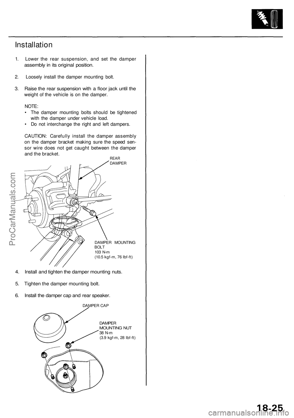
1. Lower the rear suspension, and set the damper
assembly in its original position.
2. Loosely install the damper mounting bolt.
3. Raise the rear suspension with a floor jack until the
weight of the vehicle is on the damper.
NOTE:
• The damper mounting bolts should be tightened
with the damper under vehicle load.
• Do not interchange the right and left dampers.
CAUTION: Carefully install the damper assembly
on the damper bracket making sure the speed sen-
sor wire does not get caught between the damper
and the bracket.
REAR
DAMPER
DAMPER MOUNTING
BOLT
103 N-m
(10.5 kgf-m, 76 Ibf-ft)
4. Install and tighten the damper mounting nuts.
5. Tighten the damper mounting bolt.
6. Install the damper cap and rear speaker.
DAMPER CAP
DAMPER
MOUNTING NUT
38 N-m
(3.9 kgf-m, 28 Ibf-ft)ProCarManuals.com