1996 ACURA RL KA9 wheel
[x] Cancel search: wheelPage 1223 of 1954
Troubleshooting
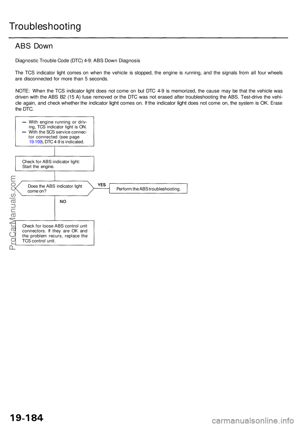
ABS Dow n
Diagnosti c Troubl e Cod e (DTC ) 4-9 : AB S Dow n Diagnosi s
Th e TC S indicato r ligh t come s o n whe n th e vehicl e i s stopped , th e engin e i s running , an d th e signal s fro m al l fou r wheel s
ar e disconnecte d fo r mor e tha n 5 seconds .
NOTE : Whe n th e TC S indicato r ligh t doe s no t com e o n bu t DT C 4- 9 i s memorized , th e caus e ma y b e tha t th e vehicl e wa s
drive n wit h th e AB S B 2 (1 5 A ) fus e remove d o r th e DT C wa s no t erase d afte r troubleshootin g th e ABS . Test-driv e th e vehi -
cle again , and chec k whethe r the indicato r light come s on. I f th e indicato r light doe s not com e on, th e syste m is OK . Eras e
the DTC .
Does th e AB S indicato r ligh t
com e on ? Perfor
m th e AB S troubleshooting .
Chec k fo r loos e AB S contro l uni t
connectors . I f the y ar e O K an d
th e proble m recurs , replac e th e
TC S contro l unit .
Chec
k fo r AB S indicato r light :
Star t th e engine .
Wit
h engin e runnin g o r driv -
ing , TC S indicato r ligh t i s ON .
Wit h th e SC S servic e connec -
to r connecte d (se e pag e
19-159 ), DT C 4- 9 is indicated .
ProCarManuals.com
Page 1234 of 1954
Component Locations
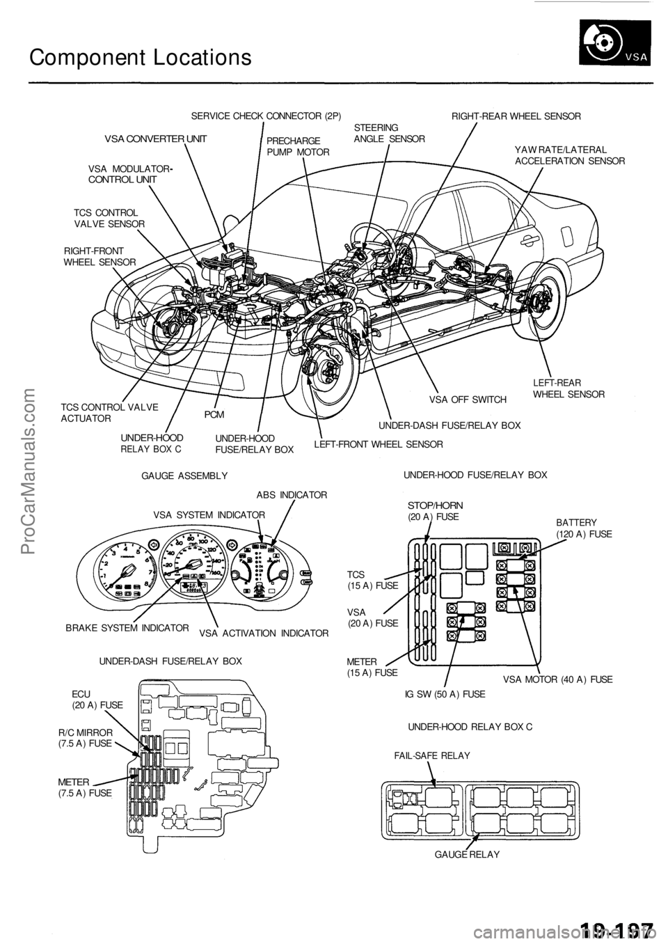
SERVICE CHECK CONNECTOR (2P)
RIGHT-REAR WHEEL SENSOR
VSA CONVERTER UNIT
VSA MODULATOR
CONTROL UNIT
TCS CONTROL
VALVE SENSOR
RIGHT-FRONT
WHEEL SENSOR
PRECHARGE
PUMP MOTOR
STEERING
ANGLE SENSOR
YAW RATE/LATERAL
ACCELERATION SENSOR
TCS CONTROL VALVE
ACTUATOR
UNDER-HOOD
RELAY BOX C
UNDER-HOOD
FUSE/RELAY BOX
VSA OFF SWITCH
UNDER-DASH FUSE/RELAY BOX
LEFT-FRONT WHEEL SENSOR
LEFT-REAR
WHEEL SENSOR
GAUGE ASSEMBLY
ABS INDICATOR
VSA SYSTEM INDICATOR
UNDER-HOOD FUSE/RELAY BOX
STOP/HORN
(20 A) FUSE
BRAKE SYSTEM INDICATOR
VSA ACTIVATION INDICATOR
UNDER-DASH FUSE/RELAY BOX
TCS
(15 A) FUSE
VSA
(20 A) FUSE
METER
(15 A) FUSE
ECU
(20 A) FUSE
METER
(7.5 A) FUSE
BATTERY
(120 A) FUSE
VSA MOTOR (40 A) FUSE
IG SW (50 A) FUSE
UNDER-HOOD RELAY BOX C
FAIL-SAFE RELAY
GAUGE RELAY
PCM
R/C MIRROR
(7.5 A) FUSEProCarManuals.com
Page 1239 of 1954
Troubleshooting Precaution s
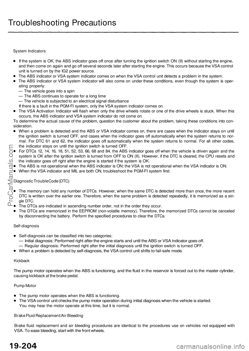
System Indicator s
If th e syste m is OK , th e AB S indicato r goe s of f onc e afte r turnin g th e ignitio n switc h O N (II ) withou t startin g th e engine ,
an d the n com e o n agai n an d g o of f severa l second s late r afte r startin g th e engine . Thi s occur s becaus e th e VS A contro l
uni t i s turne d o n b y th e IG 2 powe r source .
Th e AB S indicato r o r VS A syste m indicato r come s o n whe n th e VS A contro l uni t detect s a proble m in th e system .
Th e AB S indicato r o r VS A syste m indicato r wil l als o com e o n unde r thes e conditions , eve n thoug h th e syste m is oper -
atin g properly :
— Th e vehicl e goe s int o a spi n
— Th e AB S continue s t o operat e fo r a lon g tim e
— Th e vehicl e is subjecte d to a n electrica l signa l disturbanc e
I f ther e is a faul t i n th e PGM-F I system , onl y th e VS A syste m indicato r come s on .
Th e VS A Activatio n Indicato r wil l flas h whe n onl y th e driv e wheel s rotat e o r on e o f th e driv e wheel s is stuck . Whe n thi s
occurs , th e AB S indicato r an d VS A syste m indicato r d o no t com e on .
T o determin e th e actua l caus e o f th e problem , questio n th e custome r abou t th e problem , takin g thes e condition s int o con -
sideration .
Whe n a proble m is detecte d an d th e AB S o r VS A indicato r come s on , ther e ar e case s whe n th e indicato r stay s o n unti l
th e ignitio n switc h i s turne d OFF , an d case s whe n th e indicato r goe s of f automaticall y whe n th e syste m return s t o nor -
mal . Fo r DT C 6 1 an d 62 , th e indicato r goe s of f automaticall y whe n th e syste m return s t o normal . Fo r al l othe r codes ,
th e indicato r stay s o n unti l th e ignitio n switc h is turne d OFF .
Fo r DTC s 12 , 14 , 16 , 18 , 51 , 52 , 53 , 66 , 6 8 an d 84 , th e AB S indicato r goe s of f whe n th e vehicl e is drive n agai n an d th e
syste m is O K afte r th e ignitio n switc h is turne d fro m OF F to O N (II) . However , i f th e DT C is cleared , th e CP U reset s an d
th e indicato r goe s of f righ t afte r th e engin e is starte d if th e syste m is OK .
Th e AB S is no t operationa l whe n th e AB S indicato r i s ON ; th e VS A is no t operationa l whe n th e VS A indicato r i s ON .
Whe n th e VS A indicato r an d MI L ar e bot h ON , troubleshoo t th e PGM-F I syste m first .
Diagnosti c Troubl e Cod e (DTC )
Th e memor y ca n hol d an y numbe r o f DTCs . However , whe n th e sam e DT C is detecte d mor e tha n once , th e mor e recen t
DT C is writte n ove r th e earlie r one . Therefore , whe n th e sam e proble m is detecte d repeatedly , i t i s memorize d a s a sin -
gle DTC .
The DTC s ar e indicate d in ascendin g numbe r order , no t i n th e orde r the y occur .
Th e DTC s ar e memorize d in th e EEPRO M (non-volatil e memory) . Therefore , th e memorize d DTC s canno t b e cancele d
b y disconnectin g th e battery . Perfor m th e specifie d procedure s to clea r th e DTCs .
Self-diagnosi s
Self-diagnosis can be classifie d int o tw o categories :
— Initia l diagnosis : Performe d righ t afte r th e engin e start s an d unti l th e AB S o r VS A indicato r goe s off .
— Regula r diagnosis : Performe d righ t afte r th e initia l diagnosi s unti l th e ignitio n switc h is turne d OFF .
When a proble m is detecte d b y self-diagnosis , th e VS A contro l uni t shift s to fail-saf e mode .
Kickbac k
The pum p moto r operate s whe n th e AB S is functioning , an d th e flui d in th e reservoi r i s force d ou t t o th e maste r cylinder ,
causing kickbac k a t th e brak e pedal .
Pum p Moto r
Th e pum p moto r operate s whe n th e AB S is functioning .
The VS A contro l uni t check s th e pum p moto r operatio n durin g initia l diagnosi s whe n th e vehicl e is started .
You ma y hea r th e moto r operat e a t thi s time , bu t i t i s normal .
Brak e Flui d Replacement/Ai r Bleedin g
Brak e flui d replacemen t an d ai r bleedin g procedure s ar e identica l t o th e procedure s us e o n vehicle s no t equippe d wit h
VSA . T o eas e bleeding , star t wit h th e fron t wheels .
ProCarManuals.com
Page 1256 of 1954
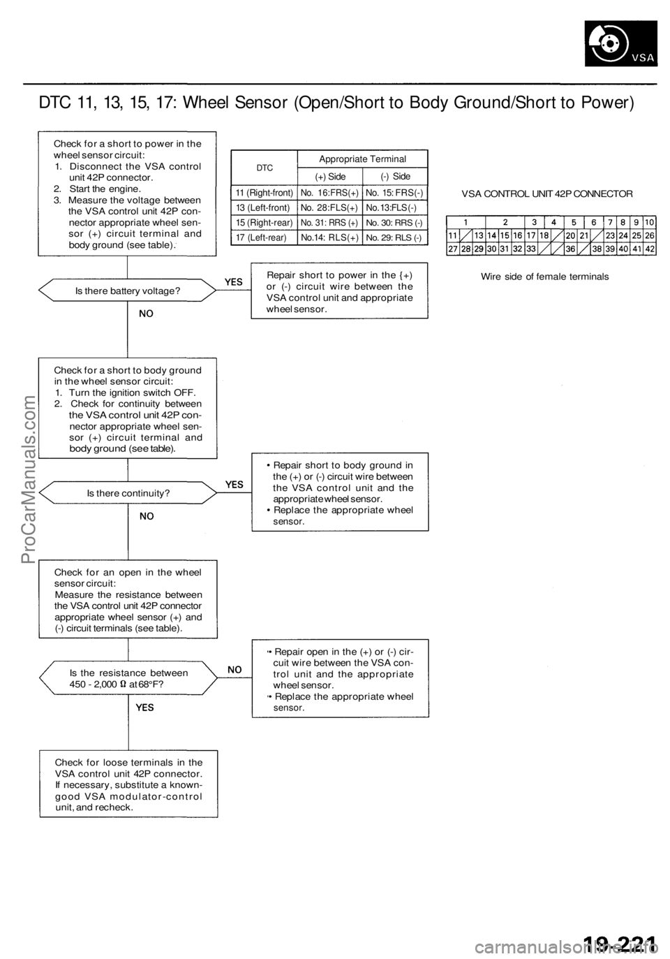
DTC 11, 13, 15, 17: Wheel Sensor (Open/Short to Body Ground/Short to Power)
Check for a short to power in the
wheel sensor circuit:
1. Disconnect the VSA control
unit 42P connector.
2. Start the engine.
3. Measure the voltage between
the VSA control unit 42P con-
nector appropriate wheel sen-
sor (+) circuit terminal and
body ground (see table).
DTC
11 (Right-front)
13 (Left-front)
15 (Right-rear)
17 (Left-rear)
Appropriate Terminal
(+) Side
No. 16:FRS(+)
No. 28:FLS(+)
No. 31: RRS (+)
No.14: RLS(+)
(-) Side
No. 15: FRS(-)
No. 13:FLS (-)
No. 30:
RRS
(-)
No. 29: RLS (-)
VSA CONTROL UNIT 42P CONNECTOR
Is there battery voltage?
Repair short to power in the {+)
or (-) circuit wire between the
VSA control unit and appropriate
wheel sensor.
Wire side of female terminals
Check for a short to body ground
in the wheel sensor circuit:
1. Turn the ignition switch OFF.
2. Check for continuity between
the VSA control unit 42P con-
nector appropriate wheel sen-
sor (+) circuit terminal and
body ground (see table).
Is there continuity?
Repair short to body ground in
the (+) or (-) circuit wire between
the VSA control unit and the
appropriate wheel sensor.
Replace the appropriate wheel
sensor.
Check for an open in the wheel
sensor circuit:
Measure the resistance between
the VSA control unit 42P connector
appropriate wheel sensor (+) and
(-) circuit terminals (see table).
Is the resistance between
450 - 2,000 at 68°F?
• Repair open in the (+) or (-) cir-
cuit wire between the VSA con-
trol unit and the appropriate
wheel sensor.
• Replace the appropriate wheel
sensor.
Check for loose terminals in the
VSA control unit 42P connector.
If necessary, substitute a known-
good VSA modulator-control
unit, and recheck.ProCarManuals.com
Page 1257 of 1954
Troubleshooting
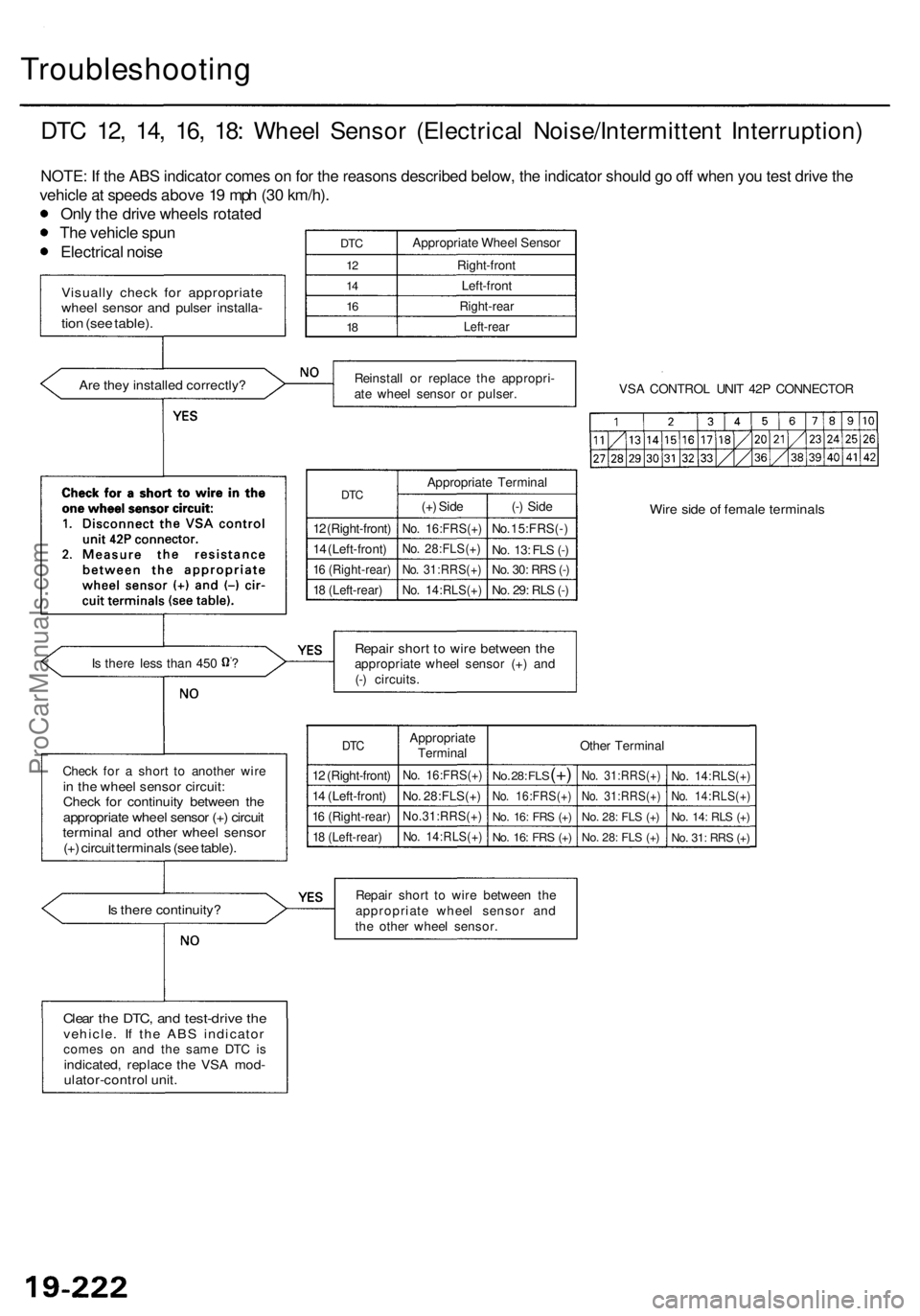
DTC 12 , 14 , 16 , 18 : Whee l Senso r (Electrica l Noise/Intermitten t Interruption )
NOTE: If the ABS indicator comes on for the reasons described below, the indicator should go off when you test drive the
vehicle a t speed s abov e 1 9 mp h (3 0 km/h) .
Onl y th e driv e wheel s rotate d
Th e vehicl e spu n
Electrica l nois e
Is ther e continuity ?
DTC
12
1 4
16
18
Appropriat e Whee l Senso r
Right-fron t
Left-fron t
Right-rea r
Left-rear
Reinstal l o r replac e th e appropri -
at e whee l senso r o r pulser . VS
A CONTRO L UNI T 42 P CONNECTO R
DTC
12 (Right-front )
1 4 (Left-front )
16 (Right-rear )
18 (Left-rear )
Appropriat e Termina l
(+ ) Sid e
No. 16:FRS(+ )
No. 28:FLS(+ )
No. 31:RRS(+ )
No. 14:RLS(+ )
(-) Sid e
No. 15:FRS( - )
No . 13 : FL S (- )
No . 30 : RR S (- )
No . 29 : RL S (- )
Wir e sid e o f femal e terminal s
Repair shor t t o wir e betwee n th eappropriat e whee l senso r (+ ) an d
(- ) circuits .
DTC
12 (Right-front )
1 4 (Left-front )
16 (Right-rear )
18 (Left-rear )
Appropriat e
Termina l
No. 16:FRS(+ )
No. 28:FLS(+ )
No.31:RRS(+ )
No. 14:RLS(+ )
Other Termina l
No. 28 : FL S (+)
No . 16:FRS(+ )
No. 16 : FR S (+ )
No . 16 : FR S (+ )
No . 31:RRS(+ )
No . 31:RRS(+ )
No. 28 : FL S (+ )
No . 28 : FL S (+ )
No . 14:RLS(+ )
No. 14:RLS(+ )
No. 14 : RL S (+ )
No . 31 : RR S (+ )
Repai r shor t t o wir e betwee n th e
appropriat e whee l senso r an d
th e othe r whee l sensor .
Clear th e DTC , an d test-driv e th evehicle . I f th e AB S indicato rcomes o n an d th e sam e DT C i sindicated , replac e th e VS A mod -ulator-contro l unit .
Chec k fo r a shor t t o anothe r wir ein th e whee l senso r circuit :Check fo r continuit y betwee n th eappropriat e whee l senso r (+ ) circui ttermina l an d othe r whee l senso r(+) circui t terminal s (se e table) .
Is ther e les s tha n 45 0 ?
Visuall y chec k fo r appropriat ewheel senso r an d pulse r installa -tion (se e table) .
Are the y installe d correctly ?
ProCarManuals.com
Page 1258 of 1954
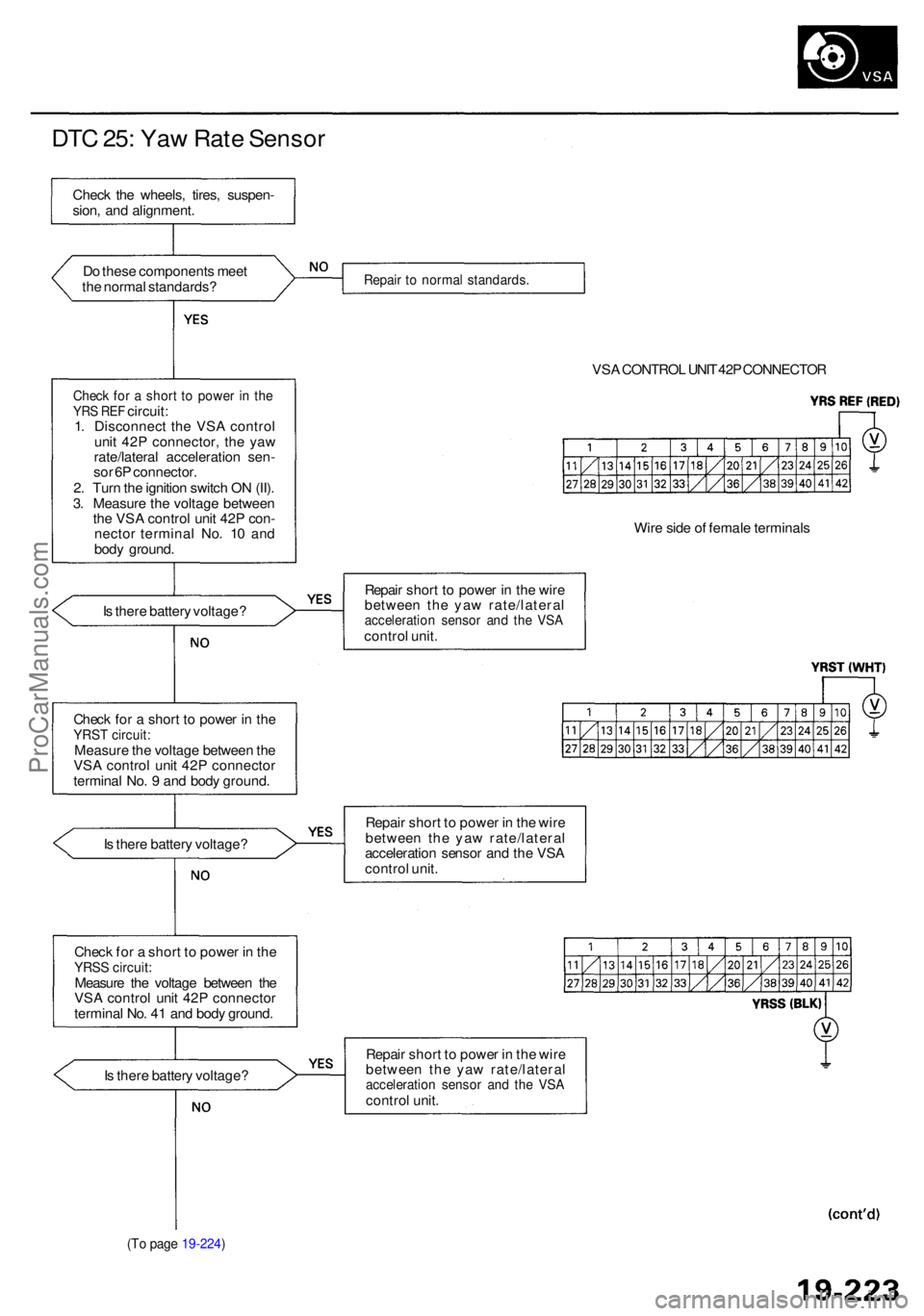
DTC 25 : Ya w Rat e Senso r
Do thes e component s mee t
th e norma l standards ?
Check fo r a shor t t o powe r i n th eYR S RE F circuit :
1 . Disconnec t th e VS A contro l
uni t 42 P connector , th e ya w
rate/latera l acceleratio n sen -
so r 6 P connector .
2 . Tur n th e ignitio n switc h O N (II) .
3 . Measur e th e voltag e betwee n
th e VS A contro l uni t 42 P con -
necto r termina l No . 1 0 an d
bod y ground .
I s ther e batter y voltage ?
Chec k fo r a shor t t o powe r i n th e
YRS T circuit :Measur e th e voltag e betwee n th e
VS A contro l uni t 42 P connecto r
termina l No . 9 an d bod y ground .
I s ther e batter y voltage ?
Chec k fo r a shor t t o powe r i n th e
YRS S circuit :Measur e th e voltag e betwee n th e
VS A contro l uni t 42 P connecto r
termina l No . 4 1 an d bod y ground .
I s ther e batter y voltage ?
(To pag e 19-224 )
Repair t o norma l standards .
VSA CONTRO L UNI T 42 P CONNECTO R
Wir e sid e o f femal e terminal s
Repai r shor t t o powe r i n th e wir e
betwee n th e ya w rate/latera l
acceleration senso r an d th e VS Acontro l unit .
Repai r shor t t o powe r i n th e wir e
betwee n th e ya w rate/latera l
acceleratio n senso r an d th e VS A
contro l unit .
Repai r shor t t o powe r i n th e wir e
betwee n th e ya w rate/latera l
acceleration senso r an d th e VS Acontro l unit .
Chec
k th e wheels , tires , suspen -
sion , an d alignment .
ProCarManuals.com
Page 1261 of 1954
Troubleshooting
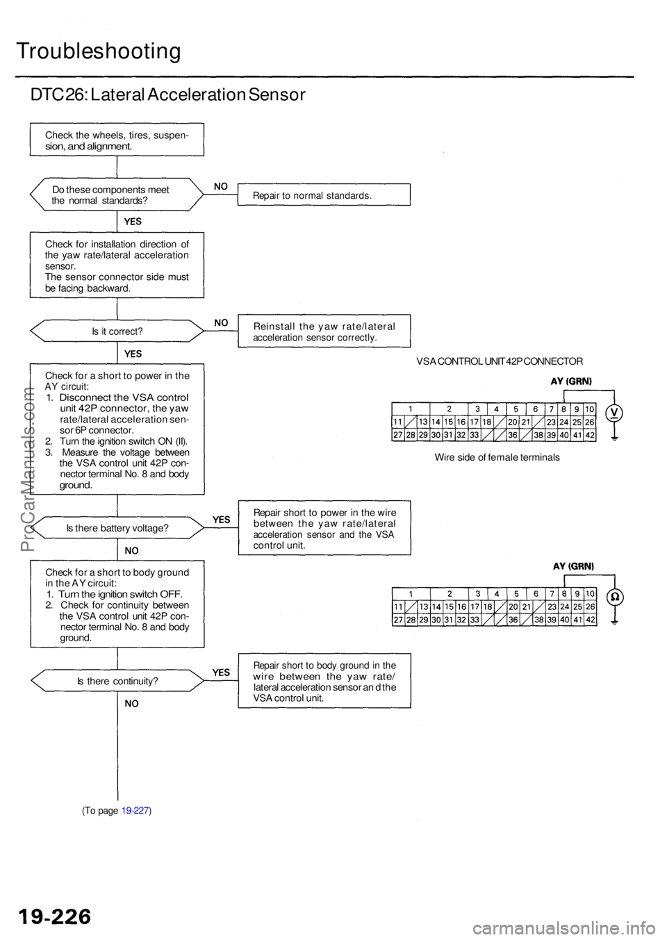
DTC 26 : Latera l Acceleratio n Senso r
Check th e wheels , tires , suspen -sion, an d alignment .
Do thes e component s mee t
th e norma l standards ?
Chec k fo r installatio n directio n o f
th e ya w rate/latera l acceleratio n
sensor.The senso r connecto r sid e mus t
b e facin g backward .
Is i t correct ?
Check fo r a shor t t o powe r i n th eAY circuit :1. Disconnec t th e VS A contro lunit 42 P connector , th e ya wrate/latera l acceleratio n sen -
so r 6 P connector .
2 . Tur n th e ignitio n switc h O N (II) .
3 . Measur e th e voltag e betwee n
th e VS A contro l uni t 42 P con -
necto r termina l No . 8 an d bod y
ground .
Is ther e batter y voltage ?
Chec k fo r a shor t t o bod y groun d
i n th e A Y circuit :
1. Tur n th e ignitio n switc h OFF .2. Chec k fo r continuit y betwee n
th e VS A contro l uni t 42 P con -
necto r termina l No . 8 an d bod y
ground .
I s ther e continuity ?
(To pag e 19-227 )
Repair t o norma l standards .
Reinstall th e ya w rate/latera lacceleration senso r correctly .
VSA CONTRO L UNI T 42 P CONNECTO R
Wir e sid e o f femal e terminal s
Repai r shor t t o powe r i n th e wir e
betwee n th e ya w rate/latera l
acceleration senso r an d th e VS Acontro l unit .
Repai r shor t t o bod y groun d in th ewir e betwee n th e ya w rate /lateral acceleratio n senso r a n d th e
VS A contro l unit .
ProCarManuals.com
Page 1279 of 1954
Troubleshooting
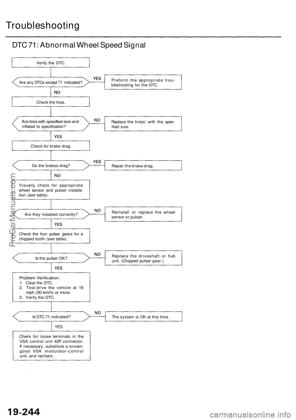
DTC 71: Abnormal Wheel Speed Signal
Are any DTCs except 71 indicated?
Check the tires.
Are tires with specified size and
inflated to specification?
Check for brake drag.
Do the brakes drag?
Visually check for appropriate
wheel sensor and pulser installa-
tion (see table).
Are they installed correctly?
Check the four pulser gears for a
chipped tooth (see table).
Is the pulser OK?
Problem Verification:
1. Clear the DTC.
2. Test-drive the vehicle at 19
mph (30 km/h) or more.
3. Verify the DTC.
Is DTC 71 indicated?
YES
Check for loose terminals in the
VSA control unit 42P connector.
If necessary, substitute a known-
good VSA modulator-control
unit, and recheck.
Preform the appropriate trou-
bleshooting for the DTC.
Replace the tire(s) with the spec-
ified size.
Repair the brake drag.
Reinstall or replace the wheel
sensor or pulser.
Replace the driveshaft or hub
unit. (Chipped pulser gear.)
The system is OK at this time.
Verify the DTC.ProCarManuals.com