Page 16 of 1954

8-4,8- 5
11-153
4-2 2
6-8 to 6-13 ,
10-1 0
4-33 , 17-15 ,22-85
19-8
19-6
22-6 8
3-2, 3- 3
8-4
, 10- 5
19-10 , 19-11 ,19-12, 19-17 , 19-18,19-19 ,19-2 3
11-124
10-5
14-10 8
15-4
*1: Replac e th e timin g bel t an d timin g balance r bel t a t 60,00 0 mile s (U.S. ) 96,00 0 k m (Canada ) i f th e vehicl e regularl y is drive n in on e o r mor e o f thes e conditions :
• I n ver y hig h temperature s (ove r 110°F , 43°C) .
• I n ver y lo w temperature s (unde r -20°F , -29°C) .
*2 : Replac e ever y 15,00 0 mile s (24,00 0 km ) i f th e vehicl e is drive n primaril y in urba n area s tha t hav e hig h concentration s o f soo t i n th e ai r fro m industr y an d diesel-powere d vehi -
Follo
w th e Sever e Condition s Maintenanc e Schedul e if th e vehicl e is drive n in Canad a o r MAINL Y unde r on e o r mor e o f th e Sever e Drivin g Condition s (pag e 3-5 ):
cles. Replace the air conditioning filter more often if air flow from the climate control system becomes less than usual.
ProCarManuals.com
Page 1430 of 1954

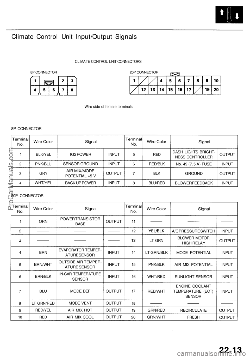
Climate Contro l Uni t Input/Outpu t Signal s
8P CONNECTO R
CLIMATE CONTRO L UNI T CONNECTOR S
20P CONNECTO R
Wire sid e o f femal e terminal s
8P CONNECTO R
Terminal
No.
1
2
3
4
Wir e Colo r
BLK/YE L
PNK/BL U
GRY
WHT/YE L
Signal
IG2 POWE R
SENSO R GROUN D
AIR MIX/MOD E
POTENTIA L + 5 V
BAC K U P POWE R INPU
T
INPU T
OUTPU T
INPU T
Termina l
No.
5
6
7
8
Wir e Colo r
RED
RED/BL K
BLK
BLU/RE D
Signal
DASH LIGHT S BRIGHT -
NESS CONTROLLER
No . 4 9 (7 . 5 A ) FUS E
GROUN D
BLOWE R FEEDBAC KOUTPU
T
INPU T
OUTPU T
INPU T
20 P CONNECTO R
Terminal
No.
1
2
3
4
5
6
7
9
10
Wir e Colo r
ORN
BRN
BRN/WH T
BRN/BLK
BLU
LT GRN/RE D
RED/YEL
RED
Signa l
POWE R TRANSISTO R
BASE
EVAPORATO R TEMPER -
ATURE SENSO R
OUTSID E AI R TEMPER -
ATUR E SENSO R
IN-CAR TEMPERATUR E
SENSOR
MODE DE F
MOD E VEN T
AIR MI X HO T
AIR MI X COO L OUTPU
T
INPU T
INPUT
INPU T
OUTPU T
OUTPU T
OUTPU T
OUTPU T
Terminal
No.
11
1 2
1 4
15
16
17
18
1 9
2 0
Wir e Colo r
LT GR N
LT GRN/BL K
PNK/BL K
WHT/RE D
RED/WH T
GRN/RED
GRN/WH T
Signal
A/C PRESSUR E SWITC H
BLOWE R MOTO R
HIG H RELA Y
MOD E POTENTIA L
AI R MI X POTENTIA L
SUNLIGH T SENSO R
ENGIN E COOLAN T
TEMPERATUR E (ECT )
SENSO R
RECIRCULAT E
FRESH
INPUT
OUTPU T
INPU T
INPU T
INPUT
INPU T
OUTPU T
OUTPU T
ProCarManuals.com
Page 1440 of 1954

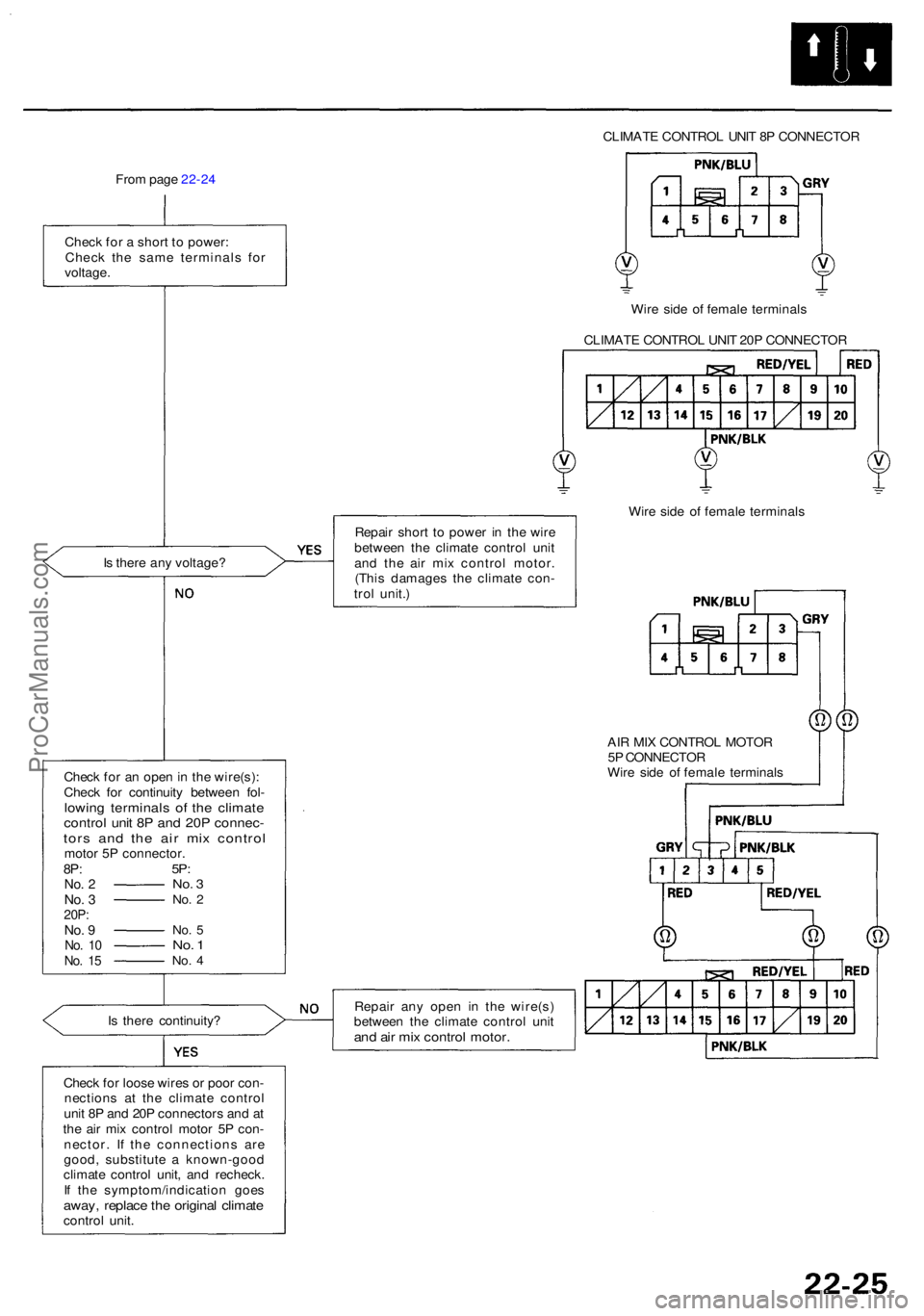
CLIMATE CONTRO L UNI T 8 P CONNECTO R
Fro m pag e 22-2 4
Chec k fo r a shor t t o power :
Chec k th e sam e terminal s fo r
voltage .
Wire sid e o f femal e terminal s
CLIMAT E CONTRO L UNI T 20 P CONNECTO R
I s ther e an y voltage ?
Chec k fo r a n ope n in th e wire(s) :
Chec k fo r continuit y betwee n fol -
lowin g terminal s o f th e climat econtrol uni t 8 P an d 20 P connec -tors an d th e ai r mi x contro lmotor 5 P connector .8P:No . 2No . 320P :No. 9No . 1 0No . 1 5
5P :No . 3No . 2
No . 5No . 1No . 4
Is ther e continuity ?
Chec k fo r loos e wire s o r poo r con -
nection s a t th e climat e contro l
uni t 8 P an d 20 P connector s an d a t
th e ai r mi x contro l moto r 5 P con -
nector . I f th e connection s ar e
good , substitut e a known-goo d
climat e contro l unit , an d recheck .
I f th e symptom/indicatio n goe s
away, replac e th e origina l climat econtro l unit . Repai
r shor t t o powe r i n th e wir e
betwee n th e climat e contro l uni t
an d th e ai r mi x contro l motor .
(Thi s damage s th e climat e con -
tro l unit. ) Wir
e sid e o f femal e terminal s
AI R MI X CONTRO L MOTO R
5 P CONNECTO R
Wir e sid e o f femal e terminal s
Repai r an y ope n i n th e wire(s )
betwee n th e climat e contro l uni t
and ai r mi x contro l motor .
ProCarManuals.com
Page 1471 of 1954

Climate Contro l Uni t
Face Panel/Butto n Replacemen t
CAUTION:
Before replacin g fac e pane l o r buttons , discharg e th e
stati c electricit y (whic h accumulate d o n yo u whe n
yo u remove d th e climat e contro l unit ) b y touchin g
th e doo r strike r o r othe r bod y parts .
D o no t touc h th e electroni c component s o n th e
printe d circui t boar d in th e climat e contro l unit .
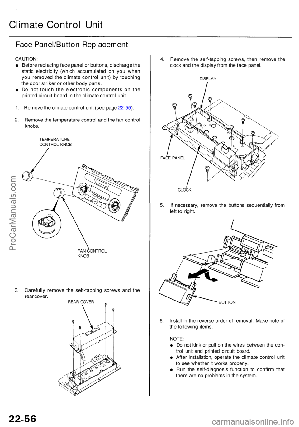
1 . Remov e th e climat e contro l uni t (se e pag e 22-55 ).
2 . Remov e th e temperatur e contro l an d th e fa n contro l
knobs.
TEMPERATUR ECONTROL KNO B
FAN CONTRO LKNOB
3. Carefull y remov e th e self-tappin g screw s an d th e
rea r cover .
REAR COVE R
4. Remov e th e self-tappin g screws , the n remov e th e
cloc k an d th e displa y fro m th e fac e panel .
DISPLA Y
CLOCK
5. I f necessary , remov e th e button s sequentiall y fro m
left t o right .
BUTTO N
6. Instal l i n th e revers e orde r o f removal . Mak e not e o f
the followin g items .
NOTE :
Do no t kin k o r pul l o n th e wire s betwee n th e con -
tro l uni t an d printe d circui t board .
Afte r installation , operat e th e climat e contro l uni t
t o se e whethe r i t work s properly .
Ru n th e self-diagnosi s functio n t o confir m tha t
ther e ar e n o problem s in th e system .
FACE PANE L
ProCarManuals.com
Page 1513 of 1954
FRONT SEA T HEATE RRELAY ('99-0 1 models )
Wir e colors :
YEL/BLK , WHT/BL K
BL K an d BLK/RE D
CLIMATE
CONTRO LUNIT
MULTIPLE X CONTRO L UNI T(PASSENGER'S )
PCM
DAS H LIGHT S BRIGHTNES S
CONTROLLE R
FAN CONTRO L
UNIT
• BLOWE R MOTO R RELA Y
Wir e colors :
BLK/YEL , BLK ,
WH T an d RED/BL K
- BLOWE R MOTO R HIG H RELA Y
Wir e colors :
BLK/YEL , L G GR N
BLU/RE D an d BL K
• AB S CONTRO L UNI T
('96-9 9 models )• VS A CONVERTE R UNI T
('0 0-0 1 models )
ProCarManuals.com