1996 ACURA RL KA9 light
[x] Cancel search: lightPage 1052 of 1954
Inspection an d Adjustmen t
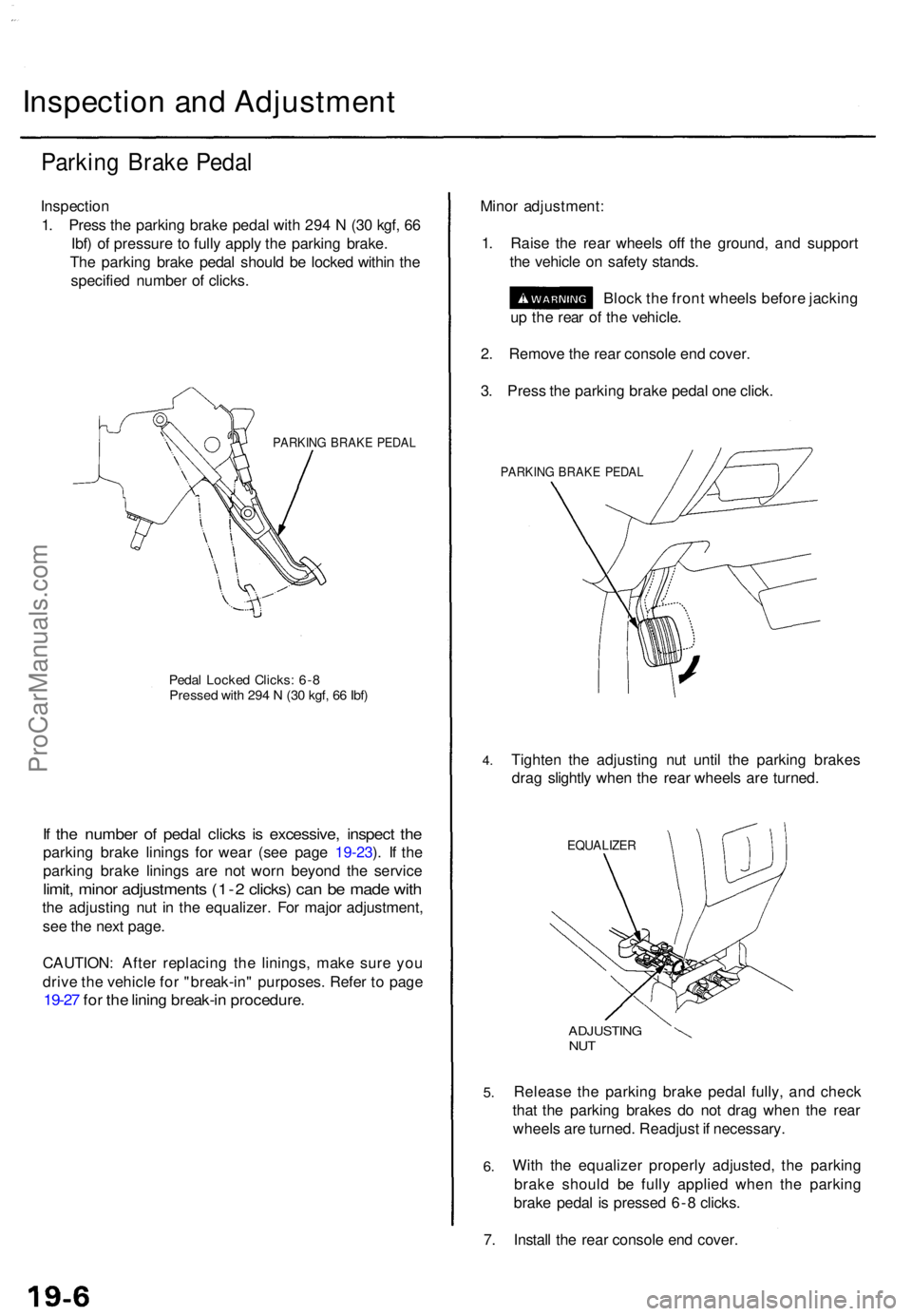
Parking Brak e Peda l
Inspectio n
1 . Pres s th e parkin g brak e peda l wit h 29 4 N (3 0 kgf , 6 6
Ibf ) o f pressur e to full y appl y th e parkin g brake .
Th e parkin g brak e peda l shoul d b e locke d withi n th e
specifie d numbe r o f clicks .
PARKIN G BRAK E PEDA L
Pedal Locke d Clicks : 6- 8Presse d wit h 29 4 N (3 0 kgf , 6 6 Ibf )
If th e numbe r o f peda l click s i s excessive , inspec t th e
parkin g brak e lining s fo r wea r (se e pag e 19-23 ). I f th e
parkin g brak e lining s ar e no t wor n beyon d th e servic e
limit, mino r adjustment s (1- 2 clicks ) ca n b e mad e wit h
the adjustin g nu t i n th e equalizer . Fo r majo r adjustment ,
se e th e nex t page .
CAUTION : Afte r replacin g th e linings , mak e sur e yo u
driv e th e vehicl e fo r "break-in " purposes . Refe r t o pag e
19-27 fo r th e linin g break-i n procedure .
Minor adjustment :
1 . Rais e th e rea r wheel s of f th e ground , an d suppor t
th e vehicl e o n safet y stands .
Bloc k th e fron t wheel s befor e jackin g
u p th e rea r o f th e vehicle .
2 . Remov e th e rea r consol e en d cover .
3 . Pres s th e parkin g brak e peda l on e click .
PARKIN G BRAK E PEDA L
4.Tighte n th e adjustin g nu t unti l th e parkin g brake s
dra g slightl y whe n th e rea r wheel s ar e turned .
EQUALIZE R
5.
6.
ADJUSTIN GNUT
Releas e th e parkin g brak e peda l fully , an d chec k
tha t th e parkin g brake s d o no t dra g whe n th e rea r
wheel s ar e turned . Readjus t i f necessary .
Wit h th e equalize r properl y adjusted , th e parkin g
brak e shoul d b e full y applie d whe n th e parkin g
brak e peda l i s presse d 6- 8 clicks .
7 . Instal l th e rea r consol e en d cover .
ProCarManuals.com
Page 1055 of 1954
Brake Syste m Indicato r
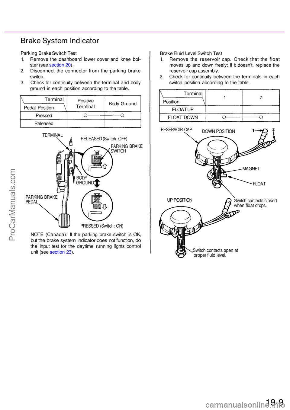
Parking Brak e Switc h Tes t
1 . Remov e th e dashboar d lowe r cove r an d kne e bol -
ste r (se e sectio n 20 ).
2 . Disconnec t th e connecto r fro m th e parkin g brak e
switch .
3 . Chec k fo r continuit y betwee n th e termina l an d bod y
groun d i n eac h positio n accordin g t o th e table .
TERMINA LRELEASE D (Switch : OFF )
PARKIN G BRAK ESWITCH
PARKIN G BRAK EPEDAL
PRESSE D (Switch : ON )
NOT E (Canada) : I f th e parkin g brak e switc h i s OK ,
but th e brak e syste m indicato r doe s no t function , d o
th e inpu t tes t fo r th e daytim e runnin g light s contro l
uni t (se e sectio n 23 ). Brak
e Flui d Leve l Switc h Tes t
1 . Remov e th e reservoi r cap . Chec k tha t th e floa t
move s u p an d dow n freely ; i f i t doesn't , replac e th e
reservoi r ca p assembly .
2 . Chec k fo r continuit y betwee n th e terminal s i n eac h
switc h positio n accordin g t o th e table .
RESERVOI R CA PDOW N POSITIO N
FLOAT
Switch contact s close dwhen floa t drops .
sSwitch contact s ope n a tprope r flui d level .
19-9
UP POSITIO N
MAGNET
BODYGROUN D
Positive
Termina lBod
y Groun d
Termina
l
Peda l Positio n
Pressed
Release d
Termina l
Positio n
FLOA T U P
FLOA T DOW N
12
ProCarManuals.com
Page 1056 of 1954
Front Brak e Pad s
Inspectio n an d Replacemen t
• Neve r us e a n ai r hos e o r dr y brus h t o clea n brake
assemblies .
• Us e a n OSHA-approve d vacuu m cleane r t o avoi d
breathin g brak e dust .
1 . Loose n th e fron t whee l nut s slightly , the n rais e th e
vehicle , an d suppor t i t o n safet y stands . Remov e
th e fron t wheels .
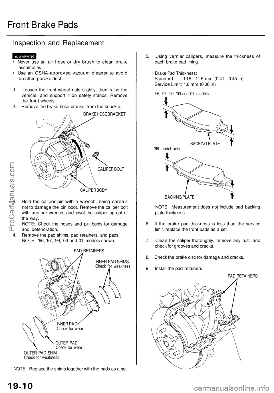
2 . Remov e th e brak e hos e bracke t fro m th e knuckle .
BRAKE HOS E BRACKE T
CALIPE R BOL T
CALIPE R BOD Y
3. Hol d th e calipe r pi n wit h a wrench , bein g carefu l
not t o damag e th e pi n boot . Remov e th e calipe r bol t
wit h anothe r wrench , an d pivo t th e calipe r u p ou t o f
the way .
NOTE : Chec k th e hose s an d pi n boot s fo r damag e
an d deterioration .
4 . Remov e th e pa d shims , pa d retainers , an d pads .
NOTE : '96 , '97 , '99 , '0 0 an d 0 1 model s shown .
PAD RETAINER S
INNER PA D SHIM SCheck fo r weakness .
OUTE R PA D
Chec k fo r wear .
OUTE R PA D SHI M
Chec k fo r weakness .
NOTE: Replac e th e shim s togethe r wit h th e pad s a s a set . 5
. Usin g vernie r calipers , measur e th e thicknes s of
eac h brak e pa d lining .
Brake Pa d Thickness :
Standard: 10. 5 - 11. 5 m m (0.4 1 - 0.4 5 in )
Servic e Limit : 1. 6 m m (0.0 6 in )
'96 , '97 , '99 , '0 0 an d 0 1 models :
BACKIN G PLAT E
NOTE: Measuremen t doe s no t includ e pa d backin g
plat e thickness .
6 . I f th e brak e pa d thicknes s i s les s tha n th e servic e
limit , replac e th e fron t pad s a s a set .
7 . Clea n th e calipe r thoroughly ; remov e an y rust , an d
chec k fo r groove s an d cracks .
8 . Chec k th e brak e dis c fo r damag e an d cracks .
9 . Instal l th e pa d retainers .
PAD RETAINER S
BACKIN
G PLAT E
'9 8 mode l onl y
INNE R PA DChec k fo r wear .
ProCarManuals.com
Page 1058 of 1954
Front Brak e Dis c
Disc Runou t Inspectio n
1. Loose n th e fron t whee l nut s slightly , the n rais e th e
vehicle , an d mak e sur e i t i s securel y supported .
Remov e th e fron t wheels .
2 . Remov e th e brak e pad s (se e pag e 19-10 ).
3 .
4 .
5 .
Inspec t th e dis c surfac e fo r damag e an d cracks .
Clean th e dis c thoroughly , an d remov e al l rust .
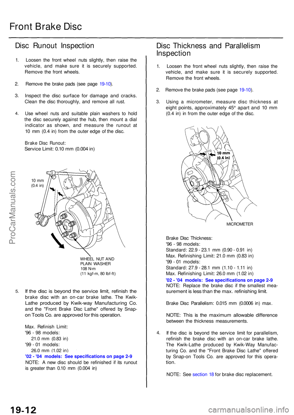
Us e whee l nut s an d suitabl e plai n washer s t o hol d
th e dis c securel y agains t th e hub , the n moun t a dia l
indicato r a s shown , an d measur e th e runou t a t
1 0 m m (0. 4 in ) fro m th e oute r edg e o f th e disc .
Brak e Dis c Runout :
Service Limit : 0.1 0 m m (0.00 4 in )
10 m m(0.4 in )
WHEE L NU T AN DPLAI N WASHE R108 N- m(11 kgf-m , 8 0 Ibf-ft )
If th e dis c i s beyon d th e servic e limit , refinis h th e
brak e dis c wit h a n on-ca r brak e lathe . Th e Kwik -
Lathe produce d b y Kwik-wa y Manufacturin g Co .
and th e "Fron t Brak e Dis c Lathe " offere d b y Snap -
on Tool s Co . ar e approve d fo r thi s operation .
Max. Refinis h Limit :
'9 6 - 9 8 models :
21.0 mm (0.8 3 in)
'99 - 0 1 models :
26.0 mm (1.0 2 in)
NOTE : A ne w dis c shoul d b e refinishe d i f it s runou t
i s greate r tha n 0.1 0 m m (0.00 4 in )
Dis c Thicknes s an d Parallelis m
Inspectio n
1. Loose n th e fron t whee l nut s slightly , the n rais e th e
vehicle , an d mak e sur e i t i s securel y supported .
Remov e th e fron t wheels .
2 . Remov e th e brak e pad s (se e pag e 19-10 ).
3 .
4.
Usin g a micrometer , measur e dis c thicknes s a t
eigh t points , approximatel y 45 ° apar t an d 1 0 m m
(0.4 in ) i n fro m th e oute r edg e o f th e disc .
MICROMETE R
Brake Dis c Thickness :
'9 6 - 9 8 models :
Standard : 22. 9 - 23. 1 m m (0.9 0 - 0.9 1 in )
Max . Refinishin g Limit : 21. 0 m m (0.8 3 in )
'9 9 - 0 1 models :
Standard : 27. 9 - 28. 1 m m (1.1 0 - 1.1 1 in )
Max . Refinishin g Limit : 26. 0 m m (1.0 2 in )
NOTE : Replac e th e brak e dis c i f th e smalles t mea -
suremen t i s les s tha n th e max . refinishin g limit .
Brak e Dis c Parallelism : 0.01 5 m m (0.000 6 in ) max .
NOTE : Thi s i s th e maximu m allowabl e differenc e
between th e thicknes s measurements .
I f th e dis c i s beyon d th e servic e limi t fo r parallelism ,
refinis h th e brak e dis c wit h a n on-ca r brak e lathe .
Th e Kwik-Lath e produce d b y Kwik-Wa y Manufac -
turin g Co . an d th e "Fron t Brak e Dis c Lathe " offere d
b y Snap-o n Tool s Co . ar e approve d fo r thi s opera -
tion.
NOTE : Se e sectio n 1 8 fo r brak e dis c replacement .
ProCarManuals.com
Page 1064 of 1954
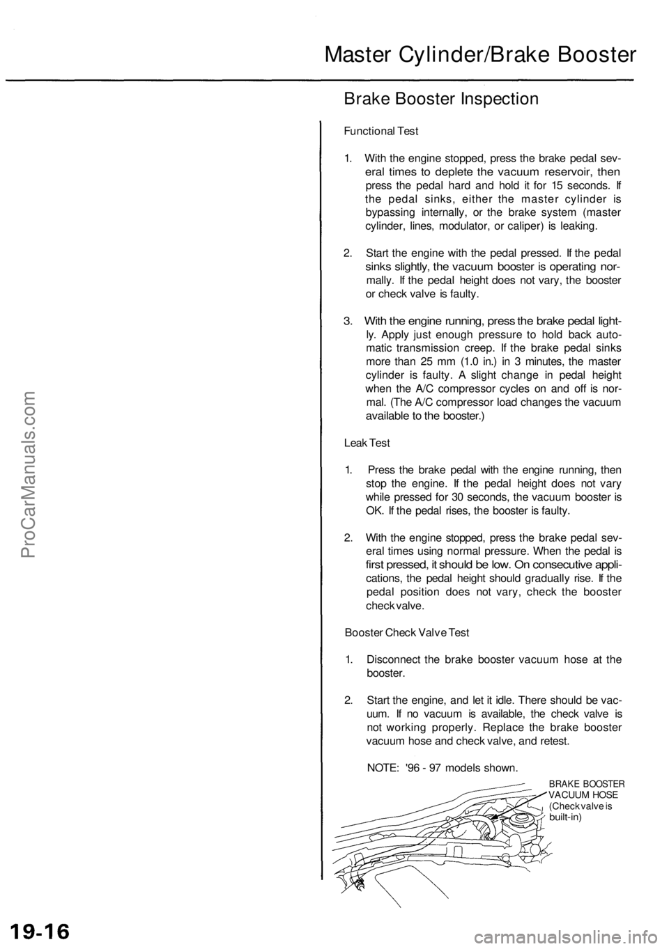
Master Cylinder/Brak e Booste r
Brake Booste r Inspectio n
Functiona l Tes t
1 . Wit h th e engin e stopped , pres s th e brak e peda l sev -
eral time s t o deplet e th e vacuu m reservoir , the n
pres s th e peda l har d an d hol d i t fo r 1 5 seconds . I f
th e peda l sinks , eithe r th e maste r cylinde r i s
bypassin g internally , o r th e brak e syste m (maste r
cylinder , lines , modulator , o r caliper ) i s leaking .
2 . Star t th e engin e wit h th e peda l pressed . I f th e peda l
sinks slightly , th e vacuu m booste r i s operatin g nor -
mally . I f th e peda l heigh t doe s no t vary , th e booste r
o r chec k valv e is faulty .
3. Wit h th e engin e running , pres s th e brak e peda l light -
ly. Appl y jus t enoug h pressur e t o hol d bac k auto -
mati c transmissio n creep . I f th e brak e peda l sink s
mor e tha n 2 5 m m (1. 0 in. ) i n 3 minutes , th e maste r
cylinde r i s faulty . A sligh t chang e i n peda l heigh t
whe n th e A/ C compresso r cycle s o n an d of f i s nor -
mal . (Th e A/ C compresso r loa d change s th e vacuu m
availabl e to th e booster. )
Leak Tes t
1 . Pres s th e brak e peda l wit h th e engin e running , the n
sto p th e engine . I f th e peda l heigh t doe s no t var y
whil e presse d fo r 3 0 seconds , th e vacuu m booste r i s
OK . I f th e peda l rises , th e booste r i s faulty .
2 . Wit h th e engin e stopped , pres s th e brak e peda l sev -
era l time s usin g norma l pressure . Whe n th e peda l i s
firs t pressed , i t shoul d b e low . O n consecutiv e appli -
cations , th e peda l heigh t shoul d graduall y rise . I f th e
peda l positio n doe s no t vary , chec k th e booste r
chec k valve .
Booste r Chec k Valv e Tes t
1 . Disconnec t th e brak e booste r vacuu m hos e a t th e
booster .
2 . Star t th e engine , an d le t i t idle . Ther e shoul d b e vac -
uum . I f n o vacuu m is available , th e chec k valv e i s
no t workin g properly . Replac e th e brak e booste r
vacuu m hos e an d chec k valve , an d retest .
NOTE : '9 6 - 9 7 model s shown .
BRAKE BOOSTE RVACUUM HOS E
(Chec k valv e is
built-in )
ProCarManuals.com
Page 1065 of 1954
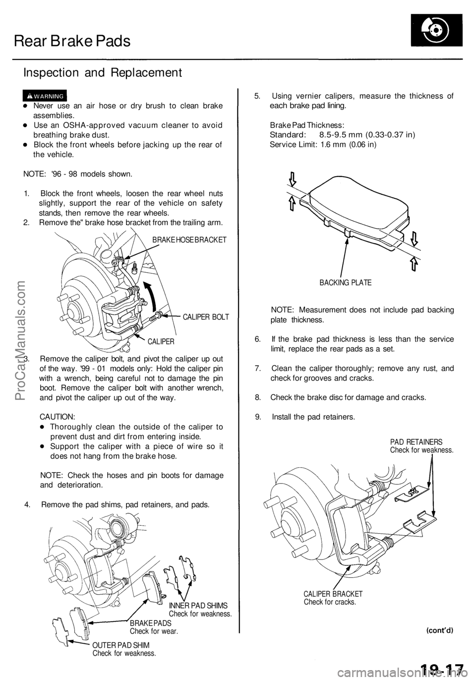
Rear Brake Pads
Inspection and Replacement
Never use an air hose or dry brush to clean brake
assemblies.
Use an OSHA-approved vacuum cleaner to avoid
breathing brake dust.
Block the front wheels before jacking up the rear of
the vehicle.
NOTE: '96 - 98 models shown.
1. Block the front wheels, loosen the rear wheel nuts
slightly, support the rear of the vehicle on safety
stands, then remove the rear wheels.
2. Remove the" brake hose bracket from the trailing arm.
BRAKE HOSE BRACKET
CALIPER BOLT
3.
CALIPER
Remove the caliper bolt, and pivot the caliper up out
of the way. '99 - 01 models only: Hold the caliper pin
with a wrench, being careful not to damage the pin
boot. Remove the caliper bolt with another wrench,
and pivot the caliper up out of the way.
CAUTION:
Thoroughly clean the outside of the caliper to
prevent dust and dirt from entering inside.
Support the caliper with a piece of wire so it
does not hang from the brake hose.
NOTE: Check the hoses and pin boots for damage
and deterioration.
4. Remove the pad shims, pad retainers, and pads.
INNER PAD SHIMS
Check for weakness.
BRAKE PADS
Check for wear.
OUTER PAD SHIM
Check for weakness.
5. Using vernier calipers, measure the thickness of
each brake pad lining.
Brake Pad Thickness:
Standard: 8.5-9.5 mm (0.33-0.37 in)
Service Limit: 1.6 mm (0.06 in)
BACKING PLATE
NOTE: Measurement does not include pad backing
plate thickness.
6. If the brake pad thickness is less than the service
limit, replace the rear pads as a set.
7. Clean the caliper thoroughly; remove any rust, and
check for grooves and cracks.
8. Check the brake disc for damage and cracks.
9. Install the pad retainers.
PAD RETAINERS
Check for weakness.
CALIPER BRACKET
Check for cracks.ProCarManuals.com
Page 1067 of 1954
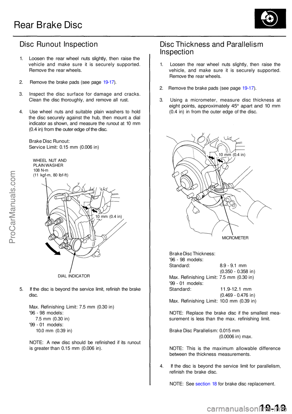
Rear Brak e Dis c
Disc Runou t Inspectio n
1. Loose n th e rea r whee l nut s slightly , the n rais e th e
vehicl e an d mak e sur e i t i s securel y supported .
Remov e th e rea r wheels .
2 . Remov e th e brak e pad s (se e pag e 19-17 ).
3 . Inspec t th e dis c surfac e fo r damag e an d cracks .
Clea n th e dis c thoroughly , an d remov e al l rust .
4 . Us e whee l nut s an d suitabl e plai n washer s t o hol d
th e dis c securel y agains t th e hub , the n moun t a dia l
indicato r a s shown , an d measur e th e runou t a t 1 0 m m
(0.4 in ) fro m th e oute r edg e o f th e disc .
Brak e Dis c Runout :
Servic e Limit : 0.1 5 m m (0.00 6 in )
WHEE L NU T AN DPLAI N WASHE R108 N- m(11 kgf-m , 8 0 Ibf-ft )
DIA L INDICATO R
5. I f th e dis c i s beyon d th e servic e limit , refinis h th e brak e
disc .
Max . Refinishin g Limit : 7. 5 m m (0.3 0 in )
'9 6 - 9 8 models :
7.5 m m (0.3 0 in)
'99 - 0 1 models :
10.0 mm (0.3 9 in)
NOTE : A ne w dis c shoul d b e refinishe d i f it s runou t
i s greate r tha n 0.1 5 m m (0.00 6 in) .
Dis c Thicknes s an d Parallelis m
Inspectio n
1. Loose n th e rea r whee l nut s slightly , the n rais e th e
vehicle , an d mak e sur e i t i s securel y supported .
Remov e th e rea r wheels .
2 . Remov e th e brak e pad s (se e pag e 19-17 ).
3 . Usin g a micrometer , measur e dis c thicknes s a t
eigh t points , approximatel y 45 ° apar t an d 1 0 m m
(0.4 in ) i n fro m th e oute r edg e o f th e disc .
MICROMETE R
Brake Dis c Thickness :
'9 6 - 9 8 models :
Standard : 8. 9 - 9. 1 m m
(0.35 0 - 0.35 8 in )
Max . Refinishin g Limit : 7. 5 m m (0.3 0 in )
'9 9 - 0 1 models :
Standard : 11.9-12. 1 m m
(0.46 9 - 0.47 6 in )
Max . Refinishin g Limit : 10. 0 m m (0.3 9 in )
NOTE : Replac e th e brak e dis c i f th e smalles t mea -
suremen t i s les s tha n th e max . refinishin g limit .
Brak e Dis c Parallelism : 0.01 5 m m
(0.000 6 in ) max .
NOTE : Thi s i s th e maximu m allowabl e differenc e
betwee n th e thicknes s measurements .
4 . I f th e dis c i s beyon d th e servic e limi t fo r parallelism ,
refinis h th e brak e disc .
NOTE : Se e sectio n 1 8 fo r brak e dis c replacement .
10 m m (0. 4 in)
10 m m (0. 4 in)
ProCarManuals.com
Page 1070 of 1954
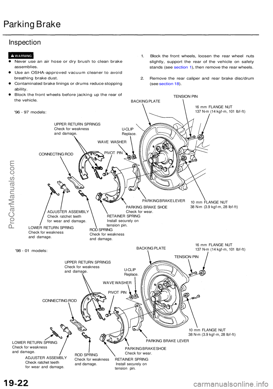
Parking Brak e
Inspectio n
Never us e a n ai r hos e o r dr y brus h t o clea n brak e
assemblies .
Use a n OSHA-approve d vacuu m cleane r t o avoi d
breathin g brak e dust .
Contaminate d brak e lining s o r drum s reduc e stoppin g
ability .
Bloc k th e fron t wheel s befor e jackin g u p th e rea r o f
th e vehicle . 1
. Bloc k th e fron t wheels , loose n th e rea r whee l nut s
slightly , suppor t th e rea r of the vehicl e o n safet y
stand s (se e sectio n 1 ), the n remov e th e rea r wheels .
2 . Remov e th e rea r calipe r an d rea r brak e disc/dru m
(se e sectio n 18 ).
TENSIO N PI NBACKIN G PLAT E
'96 - 9 7 models :
UPPER RETUR N SPRING S
Chec k fo r weaknes s
an d damag e
CONNECTIN G RO D
16 m m FLANG E NU T
13 7 N- m (1 4 kgf-m , 10 1 Ibf-ft )
ADJUSTE R ASSEMBL Y
Chec k ratche t teet h
fo r wea r an d damage .
LOWE R RETUR N SPRIN G
Chec k fo r weaknes s
an d damage . PARKIN
G BRAK E LEVE R
PARKIN G BRAK E SHO E
Chec k fo r wear .
RETAINE R SPRIN G
Instal l securel y o n
tensio n pin .ROD SPRIN GCheck fo r weaknes s
an d damage .
'98 - 0 1 models :BACKIN G PLAT E
UPPE R RETUR N SPRING S
Chec k fo r weaknes s
an d damage .
CONNECTIN G RO D
LOWE R RETUR N SPRIN G
Chec k fo r weaknes s
an d damage .
ADJUSTE R ASSEMBL Y
Check ratche t teet hfor wea r an d damage . 1
6 m m FLANG E NU T
13 7 N- m (1 4 kgf-m , 10 1 Ibf-ft )
1 0 m m FLANG E NU T
3 8 N- m (3. 9 kgf-m , 2 8 Ibf-ft )
PARKIN G BRAK E LEVE R
RO D SPRIN G PARKIN
G BRAK E SHO E
Chec k fo r wear .
Chec k fo r weaknes s RETAINE R SPRIN G
an d damage . Instal l securel y o n
tensio n pin .
PIVO
T PI N
WAV
E WASHE R
U-CLI
P
Replace .
WAV
E WASHE R
PIVO T PI NU-CLI
P
Replace .
TENSION PI N
10 m m FLANG E NU T
3 8 N- m (3. 9 kgf-m , 2 8 Ibf-ft )
ProCarManuals.com