Page 1221 of 1954
Troubleshooting
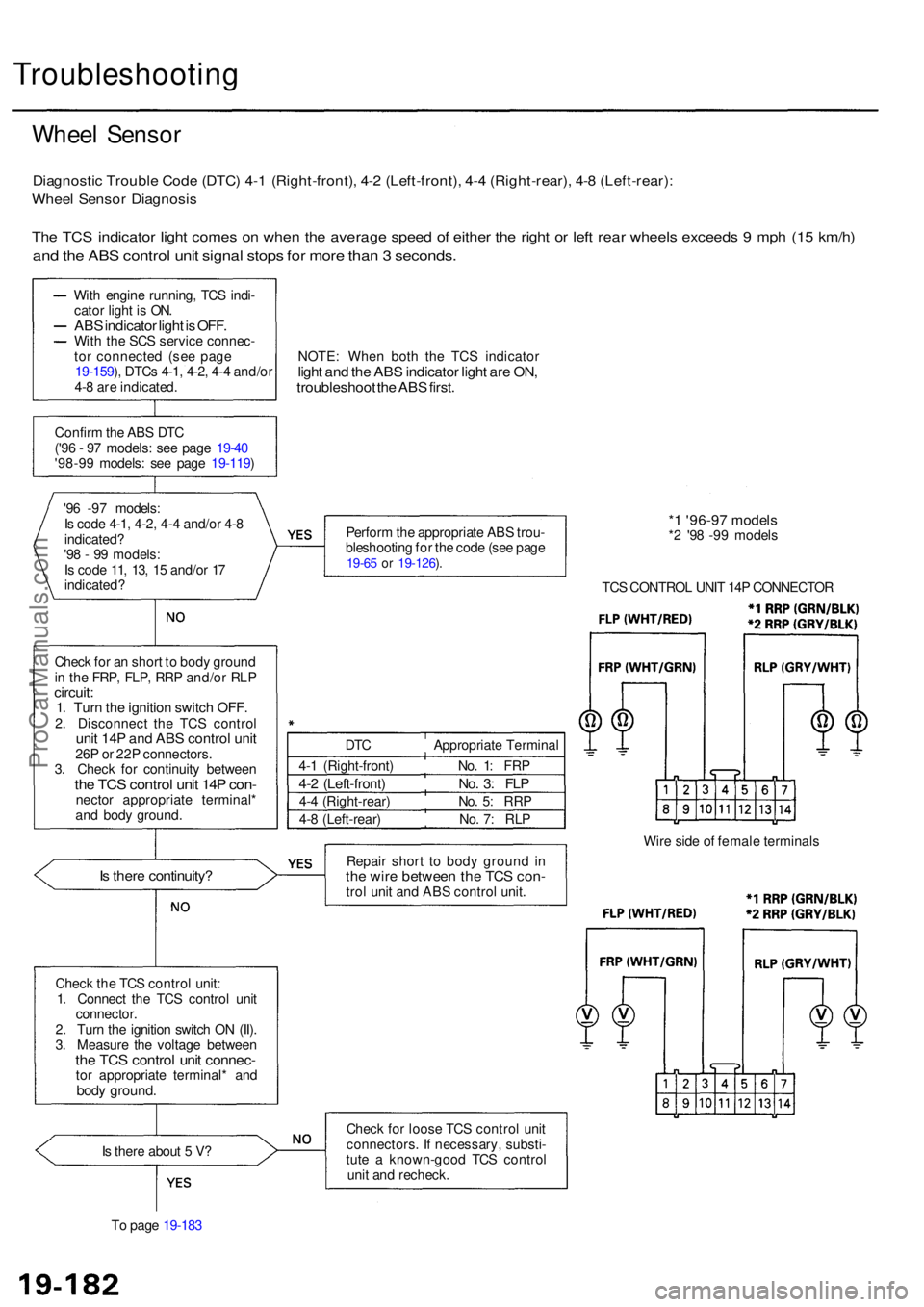
Wheel Senso r
Diagnosti c Troubl e Cod e (DTC ) 4- 1 (Right-front) , 4- 2 (Left-front) , 4- 4 (Right-rear) , 4- 8 (Left-rear) :
Wheel Senso r Diagnosi s
The TC S indicato r ligh t come s o n whe n th e averag e spee d o f eithe r th e righ t o r lef t rea r wheel s exceed s 9 mp h (1 5 km/h )
and th e AB S contro l uni t signa l stop s fo r mor e tha n 3 seconds .
With engin e running , TC S indi -
cato r ligh t i s ON .
ABS indicato r ligh t is OFF .With th e SC S servic e connec -
to r connecte d (se e pag e
19-159 ), DTC s 4-1 , 4-2 , 4- 4 and/o r
4- 8 ar e indicated . NOTE
: Whe n bot h th e TC S indicato r
light an d th e AB S indicato r ligh t ar e ON ,troubleshoo t th e AB S first .
Confir m th e AB S DT C
('9 6 - 9 7 models : se e pag e 19-4 0
'98-9 9 models : se e pag e 19-119 )
'9 6 -9 7 models :
I s cod e 4-1 , 4-2 , 4-4 and/o r 4- 8
indicated ?
'9 8 - 9 9 models :
I s cod e 11 , 13 , 1 5 and/o r 1 7
indicated ? Perfor
m th e appropriat e AB S trou -
bleshootin g fo r th e cod e (se e pag e
19-65 o r 19-126 ).
* 1 '96-9 7 model s*2 '9 8 -9 9 model s
TC S CONTRO L UNI T 14 P CONNECTO R
Chec k fo r a n shor t t o bod y groun d
i n th e FRP , FLP , RR P and/o r RL P
circuit :1. Tur n th e ignitio n switc h OFF .2. Disconnec t th e TC S contro lunit 14 P an d AB S control unit26P o r 22 P connectors .
3 . Chec k fo r continuit y betwee n
the TC S contro l uni t 14 P con -necto r appropriat e terminal *
an d bod y ground .
Is ther e continuity ?Repair shor t t o bod y groun d i nth e wir e betwee n th e TC S con -trol uni t an d AB S contro l unit . Wir
e sid e o f femal e terminal s
Chec k th e TC S contro l unit :
1 . Connec t th e TC S control unit
connector .
2 . Tur n th e ignitio n switc h O N (II) .
3 . Measur e th e voltag e betwee n
the TC S contro l uni t connec -tor appropriat e terminal * an dbody ground .
Is ther e abou t 5 V ?
T o pag e 19-18 3 Chec
k fo r loos e TC S contro l uni t
connectors . I f necessary , substi -
tut e a known-goo d TC S contro l
uni t an d recheck .
DT
C Appropriat e Termina l
4- 1 (Right-front ) No . 1 : FR P
4-2 (Left-front ) No . 3 : FL P
4-4 (Right-rear ) No . 5 : RR P
4- 8 (Left-rear ) No . 7 : RL P
ProCarManuals.com
Page 1223 of 1954
Troubleshooting
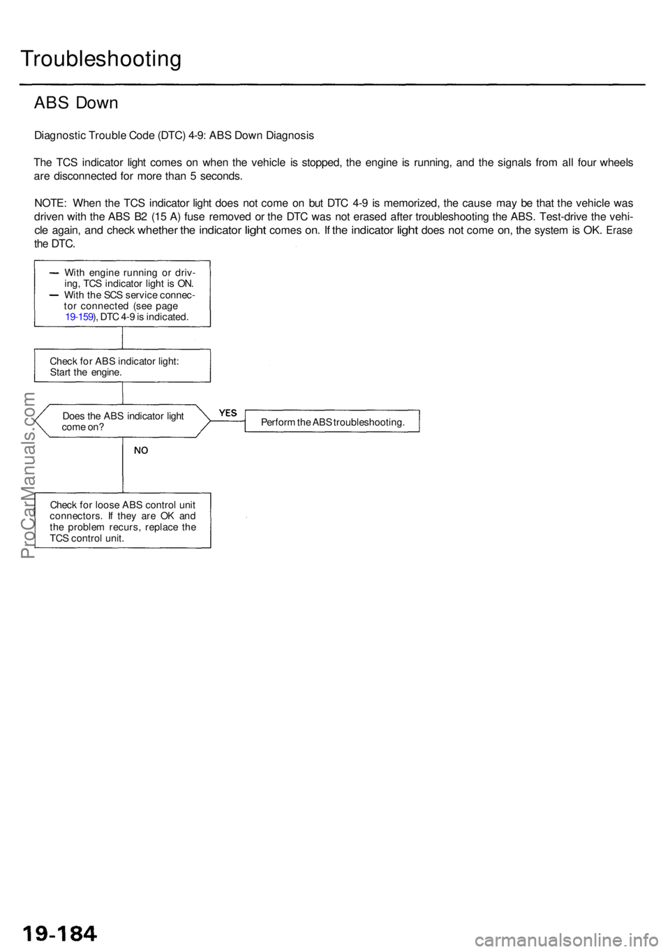
ABS Dow n
Diagnosti c Troubl e Cod e (DTC ) 4-9 : AB S Dow n Diagnosi s
Th e TC S indicato r ligh t come s o n whe n th e vehicl e i s stopped , th e engin e i s running , an d th e signal s fro m al l fou r wheel s
ar e disconnecte d fo r mor e tha n 5 seconds .
NOTE : Whe n th e TC S indicato r ligh t doe s no t com e o n bu t DT C 4- 9 i s memorized , th e caus e ma y b e tha t th e vehicl e wa s
drive n wit h th e AB S B 2 (1 5 A ) fus e remove d o r th e DT C wa s no t erase d afte r troubleshootin g th e ABS . Test-driv e th e vehi -
cle again , and chec k whethe r the indicato r light come s on. I f th e indicato r light doe s not com e on, th e syste m is OK . Eras e
the DTC .
Does th e AB S indicato r ligh t
com e on ? Perfor
m th e AB S troubleshooting .
Chec k fo r loos e AB S contro l uni t
connectors . I f the y ar e O K an d
th e proble m recurs , replac e th e
TC S contro l unit .
Chec
k fo r AB S indicato r light :
Star t th e engine .
Wit
h engin e runnin g o r driv -
ing , TC S indicato r ligh t i s ON .
Wit h th e SC S servic e connec -
to r connecte d (se e pag e
19-159 ), DT C 4- 9 is indicated .
ProCarManuals.com
Page 1283 of 1954
Troubleshooting
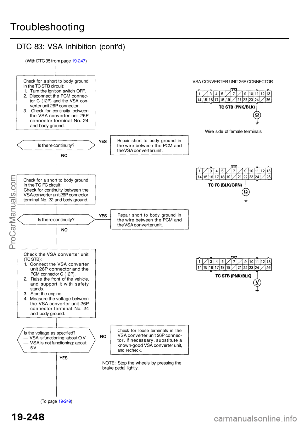
DTC 83 : VS A Inhibitio n (cont'd )
(With DT C 35 fro m pag e 19-247 )
Check fo r a shor t t o bod y groun din th e T C ST B circuit :
1 . Tur n th e ignitio n switc h OFF .
2 . Disconnec t th e PC M connec -
tor C (12P ) and th e VS A con -verte r uni t 26 P connector .
3 . Chec k fo r continuit y betwee n
th e VS A converte r uni t 26 P
connecto r termina l No . 2 4an d bod y ground .
I s ther e continuity ?
Check fo r a shor t t o bod y groun din th e T C F C circuit :
Chec k fo r continuit y betwee n th e
VS A converte r uni t 26 P connecto rterminal No . 2 2 an d bod y ground .
I s ther e continuity ?
Chec k the VSA converte r uni t
(TC STB) :1. Connec t th e VS A converte runit 26 P connecto r an d th ePC M connecto r C (12P) .2. Rais e th e fron t o f th e vehicle ,
an d suppor t i t wit h safet y
stands.3. Star t th e engine .
4 . Measur e th e voltag e betwee n
th e VS A converte r uni t 26 P
connecto r termina l No . 2 4
an d bod y ground .
I s th e voltag e a s specified ?
— VS A is functioning : abou t O V
— VS A is no t functioning : abou t5V
(T o pag e 19-249 )
VSA CONVERTE R UNI T 26 P CONNECTO R
Wire sid e o f femal e terminal s
Repair shor t t o bod y groun d i nth e wir e betwee n th e PC M an d
th e VS A converte r unit .
Repai r shor t t o bod y groun d i nth e wir e betwee n th e PC M an d
th e VS A converte r unit .
Chec k fo r loos e terminal s i n th eVS A converte r uni t 26 P connec -
tor . I f necessary , substitut e a
known-goo d VS A converte r unit ,
and recheck .
NOTE: Sto p th e wheel s b y pressin g th e
brak e peda l lightly .
ProCarManuals.com
Page 1284 of 1954
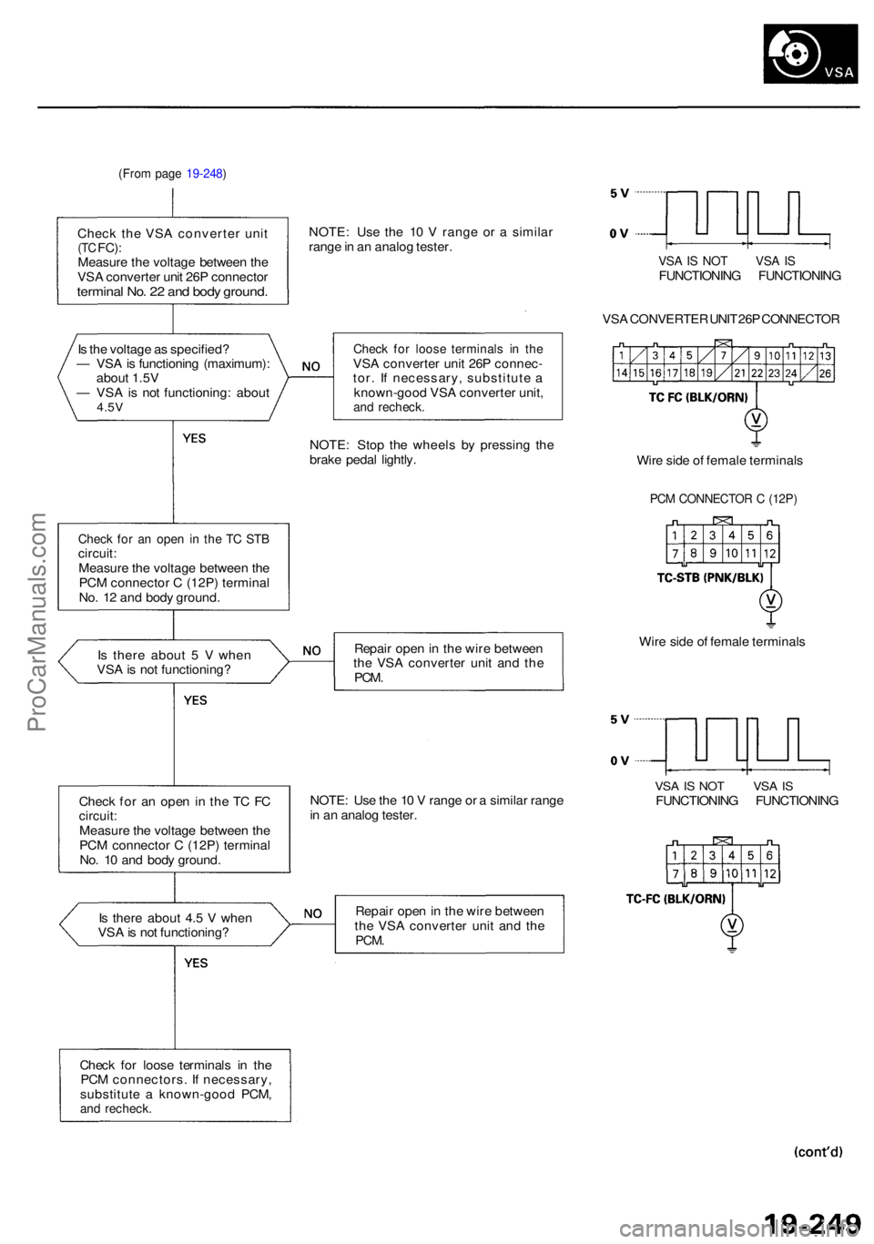
(From pag e 19-248 )
Check th e VS A converte r uni t(TC FC) :Measur e th e voltag e betwee n th e
VS A converte r uni t 26 P connecto r
terminal No . 2 2 an d bod y ground .
NOTE: Us e th e 1 0 V rang e o r a simila r
rang e in a n analo g tester .
VSA IS NO T VS A ISFUNCTIONIN G FUNCTIONIN G
VS A CONVERTE R UNI T 26 P CONNECTO R
I s th e voltag e a s specified ?
— VS A is functionin g (maximum) :
abou t 1.5 V
— VS A is no t functioning : abou t
4.5V
Chec k fo r loos e terminal s i n th eVSA converte r uni t 26 P connec -
tor . I f necessary , substitut e a
known-goo d VS A converte r unit ,
and recheck .
NOTE: Sto p th e wheel s b y pressin g th e
brak e peda l lightly .
Check fo r a n ope n i n th e T C ST Bcircuit :Measur e th e voltag e betwee n th e
PC M connecto r C (12P ) termina l
No . 1 2 an d bod y ground . Wir
e sid e o f femal e terminal s
PCM CONNECTO R C (12P )
Is ther e abou t 5 V whe n
VS A is no t functioning ? Repai
r ope n in th e wir e betwee n
th e VS A converte r uni t an d th e
PCM .
Wire sid e o f femal e terminal s
Chec k fo r a n ope n in th e T C F C
circuit :Measur e th e voltag e betwee n th e
PC M connecto r C (12P ) termina l
No . 1 0 an d bod y ground . NOTE
: Us e th e 1 0 V rang e o r a simila r rang e
i n a n analo g tester .
VSA IS NO T VS A ISFUNCTIONIN G FUNCTIONIN G
I s ther e abou t 4. 5 V whe n
VS A is no t functioning ? Repai
r ope n in th e wir e betwee n
th e VS A converte r uni t an d th e
PCM .
Chec k fo r loos e terminal s i n th e
PC M connectors . I f necessary ,
substitut e a known-goo d PCM ,
and recheck .
ProCarManuals.com
Page 1308 of 1954
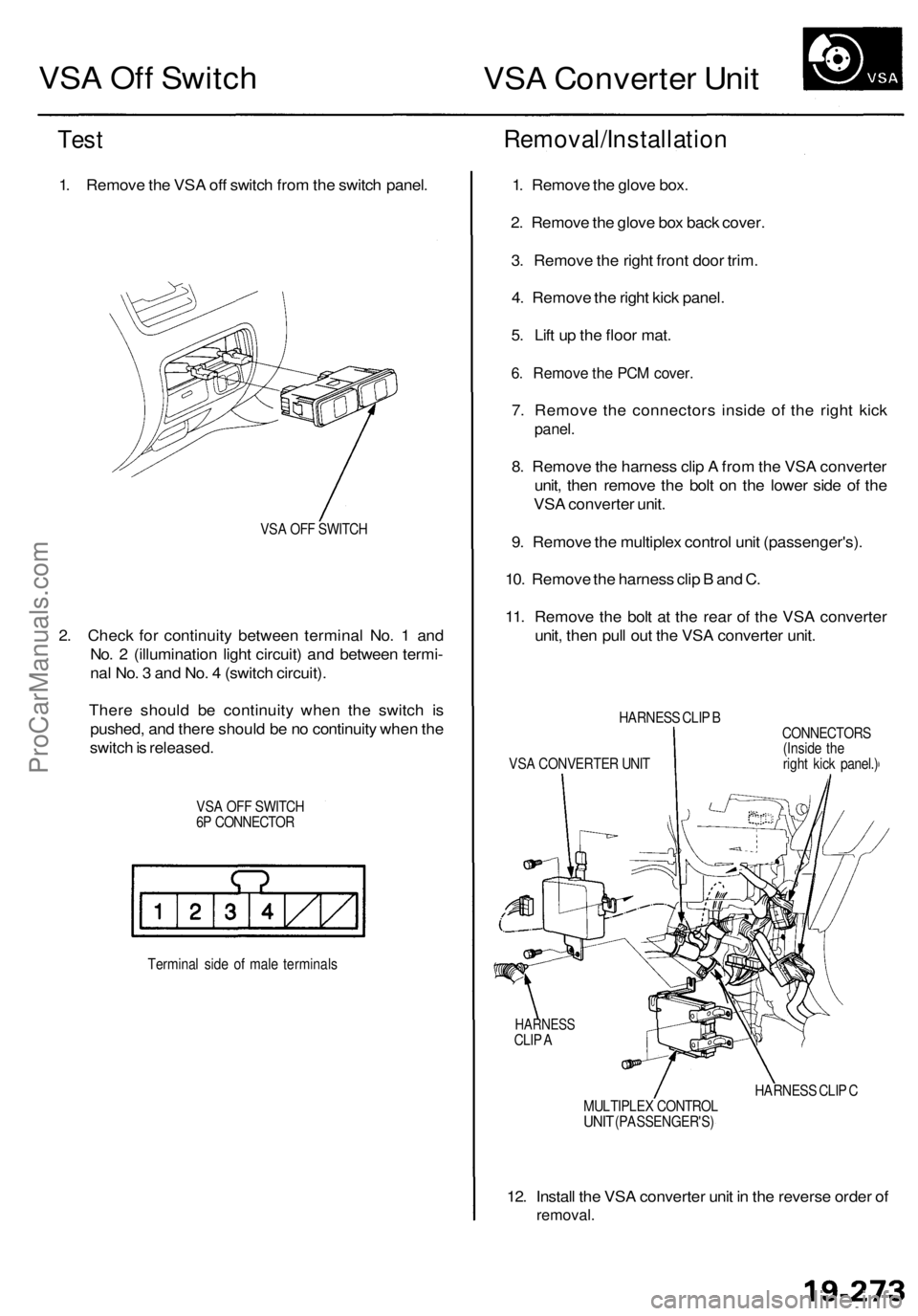
VSA Off Switch
VSA Converter Unit
Test
1. Remove the VSA off switch from the switch panel.
VSA OFF SWITCH
2. Check for continuity between terminal No. 1 and
No. 2 (illumination light circuit) and between termi-
nal No. 3 and No. 4 (switch circuit).
There should be continuity when the switch is
pushed, and there should be no continuity when the
switch is released.
VSA OFF SWITCH
6P CONNECTOR
Terminal side of male terminals
Removal/Installation
1. Remove the glove box.
2. Remove the glove box back cover.
3. Remove the right front door trim.
4. Remove the right kick panel.
5. Lift up the floor mat.
6. Remove the PCM cover.
7. Remove the connectors inside of the right kick
panel.
8. Remove the harness clip A from the VSA converter
unit, then remove the bolt on the lower side of the
VSA converter unit.
9. Remove the multiplex control unit (passenger's).
10. Remove the harness clip B and C.
11. Remove the bolt at the rear of the VSA converter
unit, then pull out the VSA converter unit.
HARNESS CLIP B
VSA CONVERTER UNIT
CONNECTORS
(Inside the
right kick panel.)
HARNESS
CLIP A
HARNESS CLIP C
MULTIPLEX CONTROL
UNIT
(PASSENGER'S)
12. Install the VSA converter unit in the reverse order of
removal.ProCarManuals.com
Page 1313 of 1954
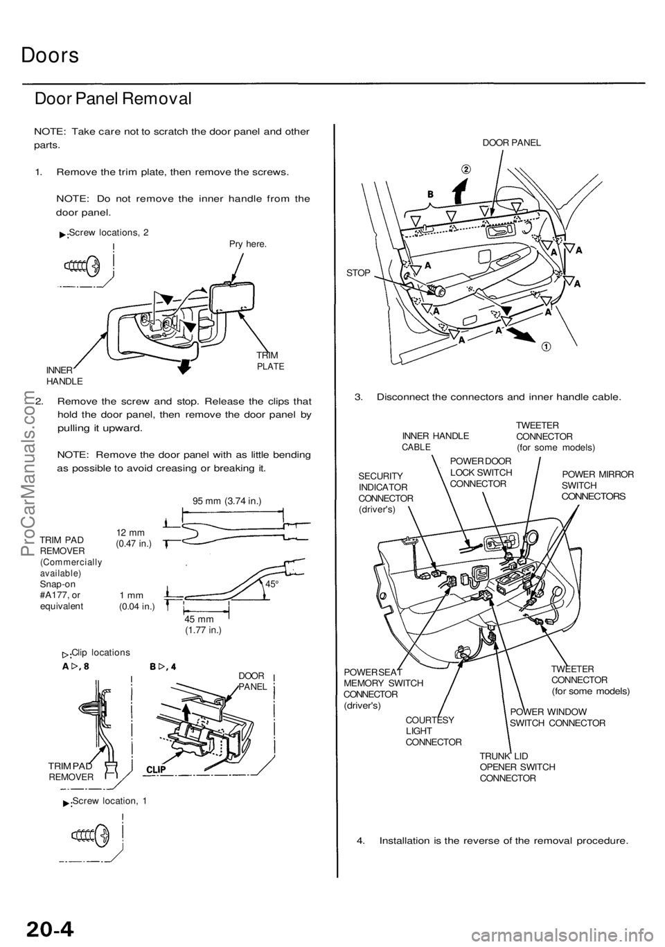
Doors
Door Pane l Remova l
NOTE: Tak e car e no t t o scratc h th e doo r pane l an d othe r
parts.
1. Remov e th e tri m plate , the n remov e th e screws .
NOTE : D o no t remov e th e inne r handl e fro m th e
doo r panel .
Screw locations , 2
Pry here .
INNE R
HANDL E TRI
M
PLAT E
2. Remov e th e scre w an d stop . Releas e th e clip s tha t
hol d th e doo r panel , the n remov e th e doo r pane l b y
pullin g it upward .
NOTE: Remov e th e doo r pane l wit h a s littl e bendin g
a s possibl e to avoi d creasin g o r breakin g it .
TRI M PA DREMOVE R(Commerciall yavailable)Snap-on
#A177 , o r
equivalen t
12 m m(0.4 7 in. )
1 m m(0.0 4 in. )
45 m m(1.7 7 in. )
Clip location s
DOORPANE L
TRIM PA DREMOVE R
DOOR PANE L
STO P
3. Disconnec t th e connector s an d inne r handl e cable .
SECURIT YINDICATO R
CONNECTO R
(driver's )
POWE R SEA T
MEMOR Y SWITC H
CONNECTO R
(driver's)
COURTES YLIGHT
CONNECTO R
TWEETERCONNECTO R(for som e models )
POWER WINDO W
SWITC H CONNECTO R
TRUN K LI D
OPENE R SWITC H
CONNECTO R
4. Installatio n i s th e revers e o f th e remova l procedure .
INNER HANDL ECABLE
POWE R DOO R
LOC K SWITC H
CONNECTO RTWEETE
R
CONNECTO R
(fo r som e models )
POWE R MIRRO R
SWITC H
CONNECTOR S
Screw location , 1
9 5 m m (3.7 4 in. )
45°
ProCarManuals.com
Page 1320 of 1954
Door Panel Removal
NOTE: Take care not to scratch the door panel and other
parts.
1. Remove the trim plate, then remove the screws.
NOTE: Do not remove the inner handle from the
door panel.
Pry here.
TRIM
PLATE
2. Remove the screw and stop. Release the clips that
hold the door panel, then remove the door panel by
pulling it upward. Disconnect the connectors and
inner handle cable.
NOTE: Remove the door panel with as little bend-
ing as possible to avoid creasing or breaking it.
95 mm
(3.74 in.)
TRIM PAD
REMOVER
(Commercially
available)
Snap-on
#A177, or
equivalent
12 mm
(0.47 in.)
1 mm
(0.04 in.)
45°
45 mm
(1.77 in.)
Clip locations
DOOR
PANEL
CLIP
POWER WINDOW
SWITCH
CONNECTOR
INNER
HANDLE
CABLE
STOP
DOOR
PANEL
ASHTRAY
LIGHT
COURTESY
LIGHT
CONNECTOR
3. Installation is the reverse of the removal procedure.
1
Screw locations, 2
INNER HANDLE
TRIM PAD
REMOVER
Screw location, 1ProCarManuals.com
Page 1328 of 1954
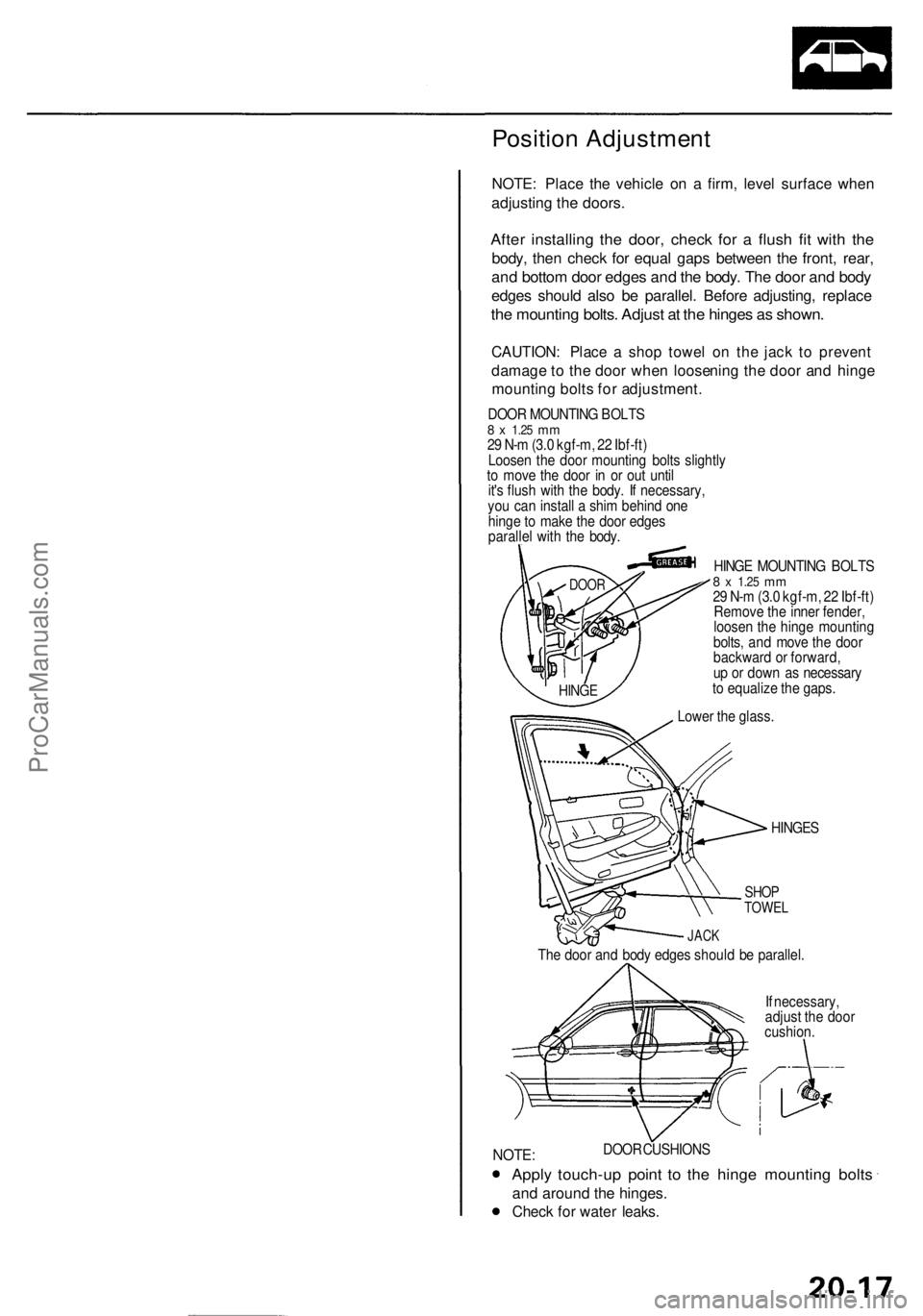
Position Adjustment
NOTE: Place the vehicle on a firm, level surface when
adjusting the doors.
After installing the door, check for a flush fit with the
body, then check for equal gaps between the front, rear,
and bottom door edges and the body. The door and body
edges should also be parallel. Before adjusting, replace
the mounting bolts. Adjust at the hinges as shown.
CAUTION: Place a shop towel on the jack to prevent
damage to the door when loosening the door and hinge
mounting bolts for adjustment.
DOOR MOUNTING BOLTS
8 x
1.25
mm
29 N-m (3.0 kgf-m, 22 Ibf-ft)
Loosen the door mounting bolts slightly
to move the door in or out until
it's flush with the body. If necessary,
you can install a shim behind one
hinge to make the door edges
parallel with the body.
HINGE MOUNTING BOLTS
8 x
1.25
mm
29 N-m (3.0 kgf-m, 22 Ibf-ft)
Remove the inner fender,
loosen the hinge mounting
bolts, and move the door
backward or forward,
up or down as necessary
to equalize the gaps.
HINGES
SHOP
TOWEL
JACK
The door and body edges should be parallel.
If necessary,
adjust the door
cushion.
DOOR CUSHIONS
NOTE:
Apply touch-up point to the hinge mounting bolts
and around the hinges.
Check for water leaks.
DOOR
HINGE
Lower the glass.ProCarManuals.com