Page 1365 of 1954
Dashboard
Componen t Removal/Installatio n
CAUTION: Whe n pryin g wit h a flat-ti p screwdriver , wra p
i t wit h protectiv e tape , an d appl y protectiv e tap e aroun d
th e relate d parts , t o preven t damage .
NOTE : Tak e car e no t t o scratc h th e dashboar d an d relate d
parts .
Instrumen t panel :
1. Remov e th e cente r ai r vent .
2 . Remov e th e climat e contro l uni t an d audi o uni t a s a n
assembl y ('9 6 - 9 8 model s se e pag e 20-51 , '9 9 - 0 1
model s se e pag e 20-52 ).
NOTE : D o no t disconnec t th e connectors .
3 . Remov e th e dashboar d lowe r cove r an d driver' s
switch trim .
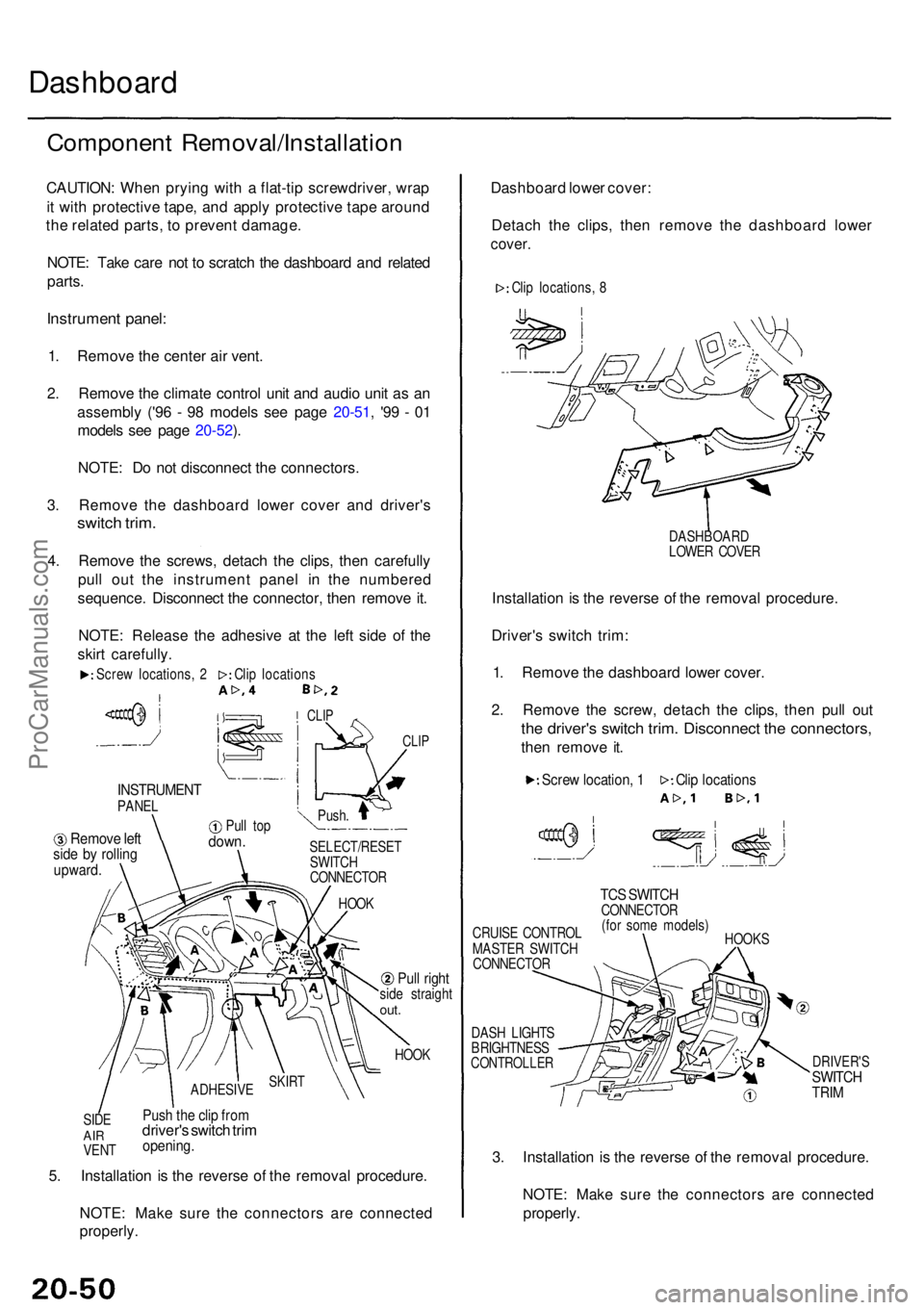
4. Remov e th e screws , detac h th e clips , the n carefull y
pul l ou t th e instrumen t pane l i n th e numbere d
sequence . Disconnec t th e connector , the n remov e it .
NOTE : Releas e th e adhesiv e a t th e lef t sid e o f th e
skir t carefully .
CLIP
INSTRUMEN TPANEL
Remov e lef tsid e b y rollin gupward .
Pull to pdown .SELECT/RESE T
SWITC H
CONNECTO R
HOO K
Pull righ tside straigh tout.
HOO K
SID E
AIRVEN T
Push th e cli p fro mdriver' s switc h tri mopening .
5. Installatio n i s th e revers e o f th e remova l procedure .
NOTE : Mak e sur e th e connector s ar e connecte d
properly . Dashboar
d lowe r cover :
Detac h th e clips , the n remov e th e dashboar d lowe r
cover.
DASHBOAR D
LOWE R COVE R
Installatio n is th e revers e o f th e remova l procedure .
Driver' s switc h trim :
1 . Remov e th e dashboar d lowe r cover .
2 . Remov e th e screw , detac h th e clips , the n pul l ou t
the driver' s switc h trim . Disconnec t th e connectors ,
then remov e it .
CRUIS E CONTRO L
MASTE R SWITC H
CONNECTO R
DAS H LIGHT S
BRIGHTNES S
CONTROLLE R
TCS SWITC HCONNECTO R
(fo r som e models )
HOOK S
DRIVER' SSWITCHTRIM
3. Installatio n i s th e revers e o f th e remova l procedure .
NOTE : Mak e sur e th e connector s ar e connecte d
properly .
Screw locations , 2 Clip location s
CLIP
Push .
SKIR TADHESIV E
Clip location s
Scre w location , 1
Cli p locations , 8
ProCarManuals.com
Page 1392 of 1954
Hood
Adjustmen t
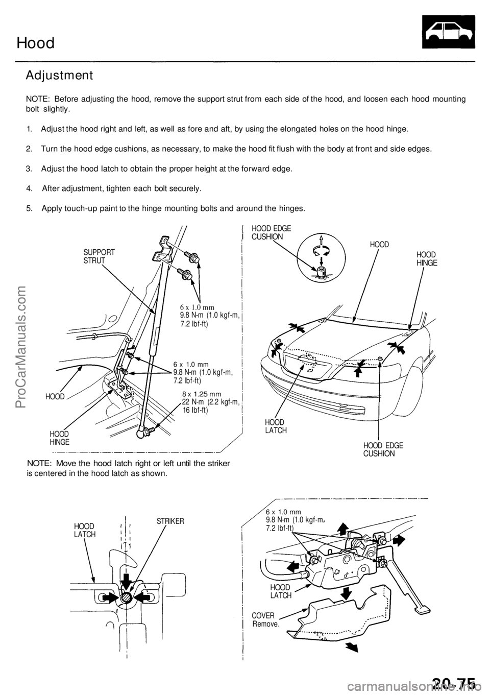
NOTE: Befor e adjustin g th e hood , remov e th e suppor t stru t fro m eac h sid e o f th e hood , an d loose n eac h hoo d mountin g
bol t slightly .
1 . Adjus t th e hoo d righ t an d left , a s wel l a s for e an d aft , b y usin g th e elongate d hole s o n th e hoo d hinge .
2 . Tur n th e hoo d edg e cushions , a s necessary , t o mak e th e hoo d fi t flus h wit h th e bod y a t fron t an d sid e edges .
3 . Adjus t th e hoo d latc h t o obtai n th e prope r heigh t a t th e forwar d edge .
4 . Afte r adjustment , tighte n eac h bol t securely .
5 . Appl y touch-u p pain t t o th e hing e mountin g bolt s an d aroun d th e hinges .
SUPPOR T
STRU T {
HOO D EDG E
I CUSHIO N
HOOD
HOO D
HING E
6 x 1. 0 m m9.8 N- m (1. 0 kgf-m ,
7. 2 Ibf-ft )
6 x 1. 0 m m9.8 N- m (1. 0 kgf-m ,
7. 2 Ibf-ft )
8 x 1.2 5 mm22 N- m (2. 2 kgf-m ,
1 6 Ibf-ft )
NOTE : Mov e th e hoo d latc h righ t o r lef t unti l th e strike r
is centere d in th e hoo d latc h a s shown .
HOODLATC H
HOOD
HOOD
HING E
HOOD EDG ECUSHIO N
HOODLATC H
STRIKE R
6 x 1. 0 m m9.8 N- m (1. 0 kgf- m
7. 2 Ibf-ft )
COVE RRemove .
HOODLATC H
ProCarManuals.com
Page 1393 of 1954
Adjustment
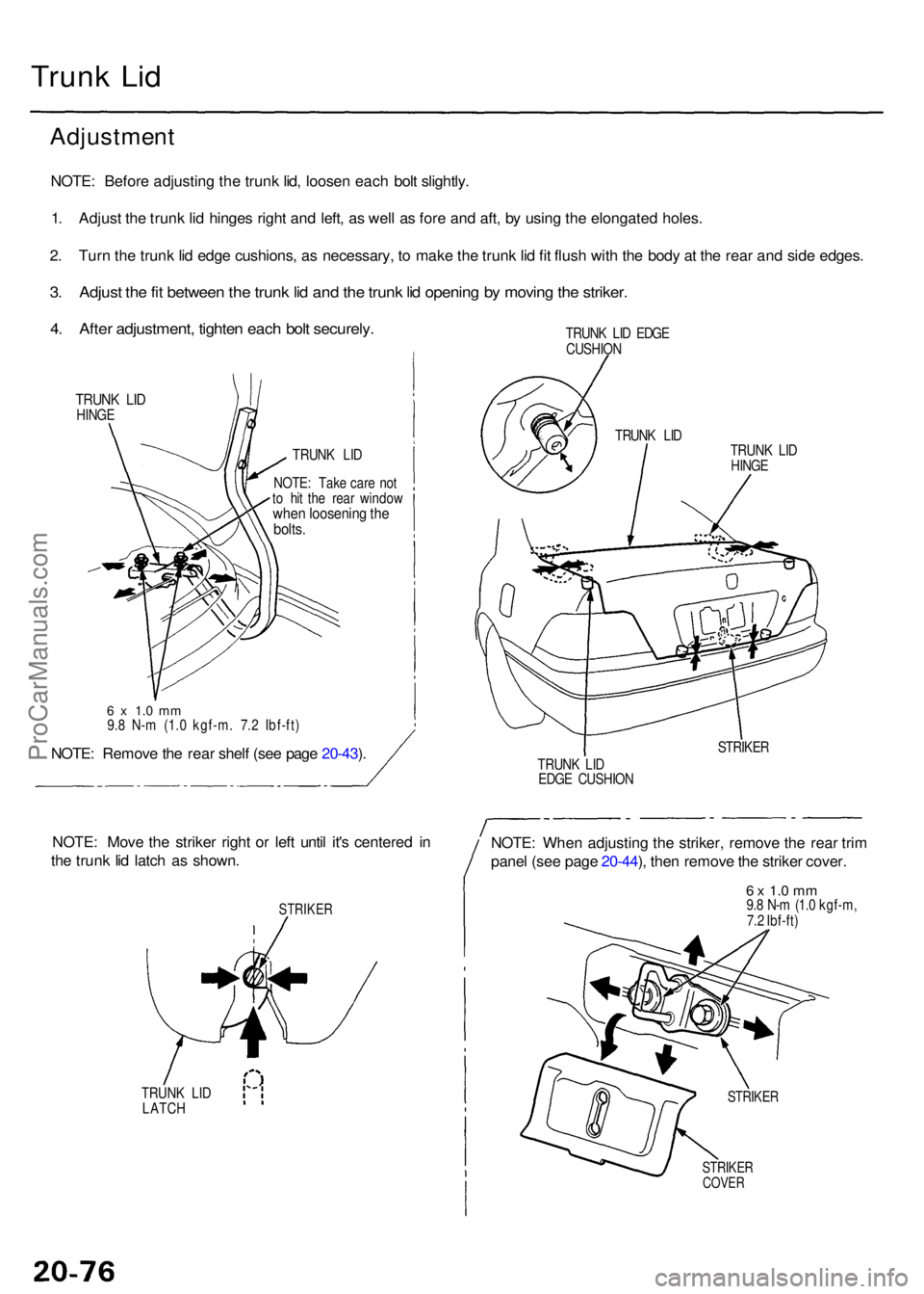
NOTE: Befor e adjustin g th e trun k lid , loose n eac h bol t slightly .
1 . Adjus t th e trun k li d hinge s righ t an d left , a s wel l a s for e an d aft , b y usin g th e elongate d holes .
2 . Tur n th e trunk lid edg e cushions , a s necessary , t o mak e th e trun k li d fi t flus h wit h th e bod y a t th e rea r an d sid e edges .
3. Adjus t th e fi t betwee n th e trun k li d an d th e trun k li d openin g b y movin g th e striker .
4. Afte r adjustment , tighte n eac h bol t securely .
TRUNK LI DHING E
TRUNK LI D
NOTE : Tak e car e no t
t o hi t th e rea r windo w
when loosenin g th ebolts .
6 x 1. 0 m m9.8 N- m (1. 0 kgf-m . 7. 2 Ibf-ft )
NOTE: Remov e th e rea r shel f (se e pag e 20-43 ).
NOTE : Mov e th e strike r righ t o r lef t unti l it' s centere d i n
th e trun k li d latc h a s shown .
STRIKE R
TRUNK LI D
LATC H TRUN
K LI D EDG E
CUSHIO N
TRUNK LI D
HING E
STRIKE R
TRUN K LI D
EDG E CUSHIO N
NOTE: Whe n adjustin g th e striker , remov e th e rea r tri m
pane l (se e pag e 20-44 ), the n remov e th e strike r cover .
6 x 1. 0 m m9.8 N- m (1. 0 kgf-m ,
7. 2 Ibf-ft )
STRIKE RCOVER
STRIKE R
TRUNK LI D
Trun k Li d
ProCarManuals.com
Page 1402 of 1954
If th e ol d moldin g is t o b e reinstalled :
Th e followin g material s an d tool s ar e require d t o repai r
the molding .
NOTE: Follo w th e manufacturer' s instructions .
Materials: (Reference )
Stripe remove r
3 M 0890 7
Strip e adhesiv e remove r
3 M 0890 8
Adhesiv e tap e
3 M Supe r Automotiv e Attachmen t Tap e
Tools :
Protectiv e tap e
Knif e o r cutte r
Spong e o r sho p towe l
Infrare d drye r Fil
m
Putt y knif e
Alcoho l
CAUTION : Pu t o n glove s to protec t you r hands .
1 . I f necessary , replac e an y damage d clip s o n th e mold -
ing.
2. Appl y th e strip e remove r evenl y t o th e bondin g sur -
fac e o f th e bod y an d molding .
3 . Cove r th e bondin g surfac e o f th e bod y an d moldin g
wit h a film , the n hea t t o 10 4 - 122° F (4 0 - 50°C ) fo r 5
- 1 0 minute s wit h a n infrare d dryer .
NOTE : Us e car e whe n heatin g t o preven t deforma -
tion o f th e bod y an d molding .
4. Scrap e th e adhesiv e tap e wit h a putt y knife .
5 . Fo r remova l o f adhesiv e tap e residue , follow-u p wit h
strip e adhesiv e remover , the n scrap e th e adhesiv e
tap e wit h a putt y knife .
6 . Remov e th e protectiv e tape , the n clea n th e bondin g
surfac e wit h a spong e dampene d in alcohol .
NOTE : Mak e sur e th e bondin g surfac e is kep t fre e o f
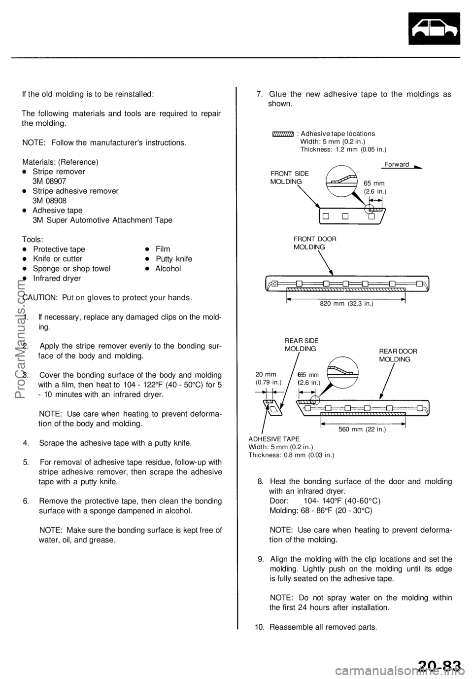
water , oil , an d grease . 7
. Glu e th e ne w adhesiv e tap e t o th e molding s a s
shown .
: Adhesiv e tap e location sWidth: 5 m m (0. 2 in. )Thickness : 1. 2 m m (0.0 5 in. )
Forwar d
FRON T SID E
MOLDIN G
FRONT DOO RMOLDIN G
820 m m (32. 3 in. )
REA R SID EMOLDIN GREAR DOO RMOLDIN G
ADHESIV E TAP EWidth : 5 m m (0. 2 in. )Thickness : 0. 8 m m (0.0 3 in. )
8. Hea t th e bondin g surfac e o f th e doo r an d moldin g
wit h a n infrare d dryer .
Door: 104 - 140° F (40-60°C )
Molding : 6 8 - 86° F (2 0 - 30°C )
NOTE : Us e car e whe n heatin g t o preven t deforma -
tion o f th e molding .
9. Alig n th e moldin g wit h th e cli p location s an d se t th e
molding . Lightl y pus h o n th e moldin g unti l it s edg e
i s full y seate d o n th e adhesiv e tape .
NOTE : D o no t spra y wate r o n th e moldin g withi n
th e firs t 2 4 hour s afte r installation .
10 . Reassembl e al l remove d parts .
560 m m (2 2 in. )
65 m m2.6 in. )20 m m(0.7 9 in. )
65 m m(2.6 in. )
ProCarManuals.com
Page 1429 of 1954
Troubleshooting
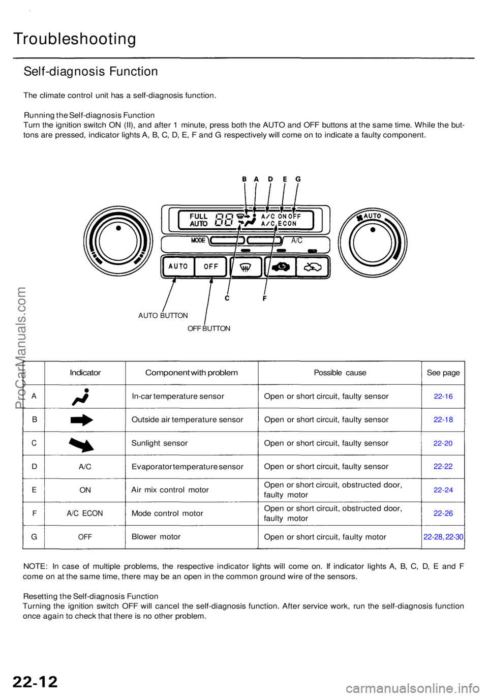
Self-diagnosis Functio n
The climat e contro l uni t ha s a self-diagnosi s function .
Runnin g th e Self-diagnosi s Functio n
Tur n th e ignitio n switc h O N (II) , an d afte r 1 minute , pres s bot h th e AUT O an d OF F button s a t th e sam e time . Whil e th e but -
ton s ar e pressed , indicato r light s A , B , C , D , E , F an d G respectivel y wil l com e o n to indicat e a fault y component .
A/C
AUT O BUTTO N
OFF BUTTO N
A
B
C
D
E
F
G
Indicator
A/C
ON
A/ C ECO N
OFF
Componen t wit h proble m
In-car temperatur e senso r
Outsid e ai r temperatur e senso r
Sunligh t senso r
Evaporato r temperatur e senso r
Ai r mi x contro l moto r
Mod e contro l moto r
Blowe r moto r Possibl
e caus e
Ope n o r shor t circuit , fault y senso r
Ope n o r shor t circuit , fault y senso r
Ope n o r shor t circuit , fault y senso r
Ope n o r shor t circuit , fault y senso r
Ope n o r shor t circuit , obstructe d door ,
fault y moto r
Ope n o r shor t circuit , obstructe d door ,
fault y moto r
Ope n o r shor t circuit , fault y moto r Se
e pag e22-1 6
22-1 8
22-20
22-2 2
22-2 4
22-26
22-28 , 22-3 0
NOTE : I n cas e o f multipl e problems , th e respectiv e indicato r light s wil l com e on . I f indicato r light s A , B , C , D , E an d F
com e o n a t th e sam e time , ther e ma y b e a n ope n in th e commo n groun d wir e o f th e sensors .
Resettin g th e Self-diagnosi s Functio n
Turnin g th e ignitio n switc h OF F wil l cance l th e self-diagnosi s function . Afte r servic e work , ru n th e self-diagnosi s functio n
onc e agai n t o chec k tha t ther e is n o othe r problem .
ProCarManuals.com
Page 1430 of 1954
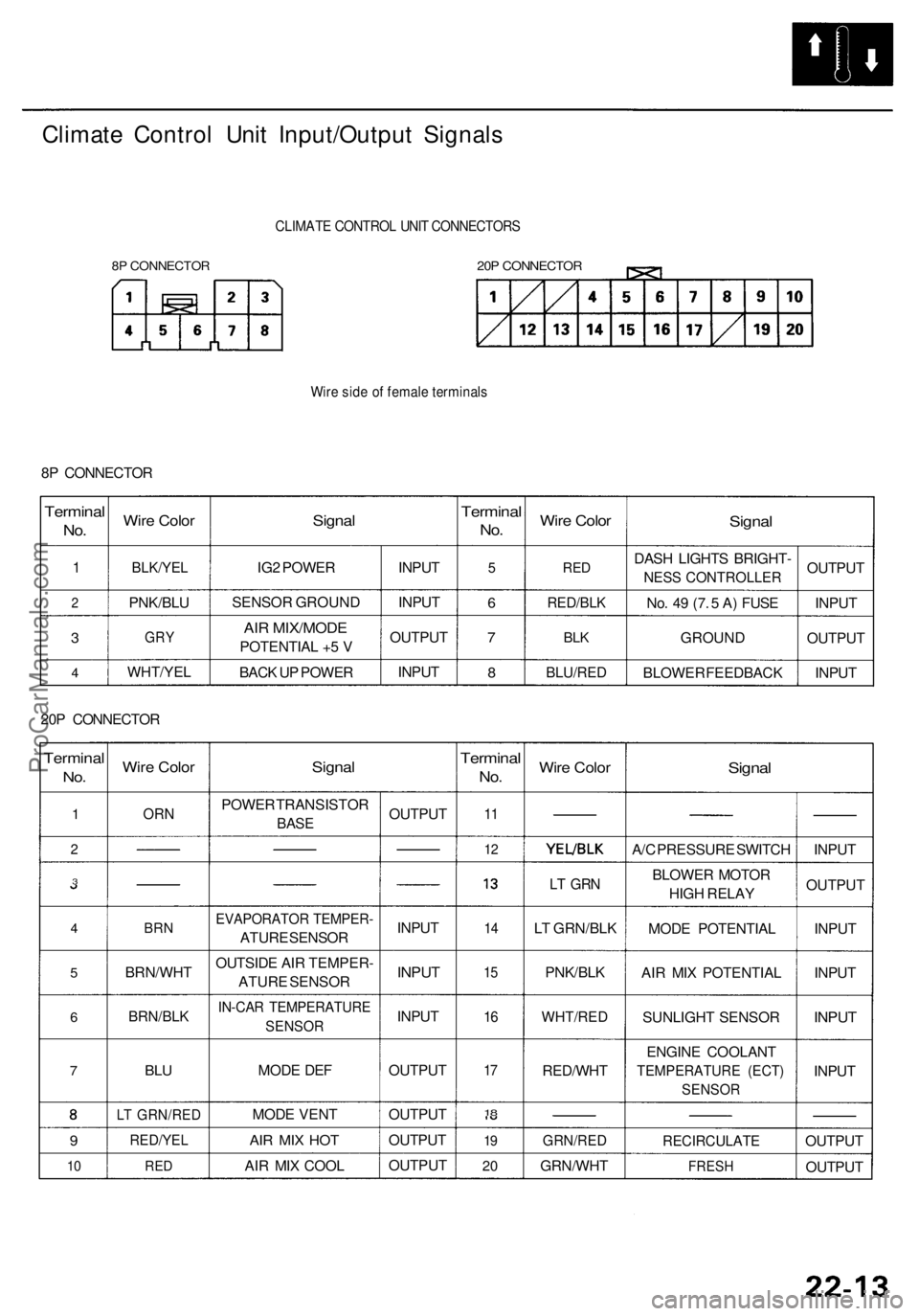
Climate Contro l Uni t Input/Outpu t Signal s
8P CONNECTO R
CLIMATE CONTRO L UNI T CONNECTOR S
20P CONNECTO R
Wire sid e o f femal e terminal s
8P CONNECTO R
Terminal
No.
1
2
3
4
Wir e Colo r
BLK/YE L
PNK/BL U
GRY
WHT/YE L
Signal
IG2 POWE R
SENSO R GROUN D
AIR MIX/MOD E
POTENTIA L + 5 V
BAC K U P POWE R INPU
T
INPU T
OUTPU T
INPU T
Termina l
No.
5
6
7
8
Wir e Colo r
RED
RED/BL K
BLK
BLU/RE D
Signal
DASH LIGHT S BRIGHT -
NESS CONTROLLER
No . 4 9 (7 . 5 A ) FUS E
GROUN D
BLOWE R FEEDBAC KOUTPU
T
INPU T
OUTPU T
INPU T
20 P CONNECTO R
Terminal
No.
1
2
3
4
5
6
7
9
10
Wir e Colo r
ORN
BRN
BRN/WH T
BRN/BLK
BLU
LT GRN/RE D
RED/YEL
RED
Signa l
POWE R TRANSISTO R
BASE
EVAPORATO R TEMPER -
ATURE SENSO R
OUTSID E AI R TEMPER -
ATUR E SENSO R
IN-CAR TEMPERATUR E
SENSOR
MODE DE F
MOD E VEN T
AIR MI X HO T
AIR MI X COO L OUTPU
T
INPU T
INPUT
INPU T
OUTPU T
OUTPU T
OUTPU T
OUTPU T
Terminal
No.
11
1 2
1 4
15
16
17
18
1 9
2 0
Wir e Colo r
LT GR N
LT GRN/BL K
PNK/BL K
WHT/RE D
RED/WH T
GRN/RED
GRN/WH T
Signal
A/C PRESSUR E SWITC H
BLOWE R MOTO R
HIG H RELA Y
MOD E POTENTIA L
AI R MI X POTENTIA L
SUNLIGH T SENSO R
ENGIN E COOLAN T
TEMPERATUR E (ECT )
SENSO R
RECIRCULAT E
FRESH
INPUT
OUTPU T
INPU T
INPU T
INPUT
INPU T
OUTPU T
OUTPU T
ProCarManuals.com
Page 1435 of 1954
Troubleshooting
Sunlight Senso r
Self-diagnosi s indicato r ligh t C come s on : A proble m in th e sunligh t senso r circuit .
The sunligh t senso r i s a ligh t sensitive , variabl e resistanc e diode . Th e resistanc e o f th e diod e increase s a s th e intensit y o f
the ligh t increases .
Check fo r a shor t i n th e wire :1. Remov e th e climat e contro lunit (se e pag e 22-55 ), an d dis -
connec t th e 8 P an d 20 P con -
nectors .
2 . Remov e th e sunligh t senso r
(se e pag e 22-62 ), an d discon -
nec t th e 2 P connector .
3 . Chec k fo r continuit y betwee n
the No . 1 6 termina l o f th e 20 Pconnecto r an d bod y ground .
T o pag e 22-2 1
ProCarManuals.com
Page 1436 of 1954
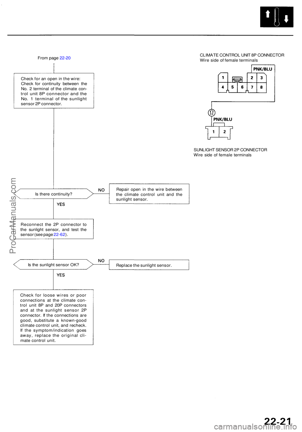
From pag e 22-2 0 CLIMAT
E CONTRO L UNI T 8 P CONNECTO R
Wir e sid e o f femal e terminal s
Chec k fo r a n ope n in th e wire :
Chec k fo r continuit y betwee n th e
No . 2 termina l o f th e climat e con -
trol uni t 8 P connecto r an d th eNo . 1 termina l o f th e sunligh tsensor 2 P connector .
SUNLIGHT SENSO R 2P CONNECTO R
Wir e sid e o f femal e terminal s
I s ther e continuity ? Repai
r ope n i n th e wir e betwee n
th e climat e contro l uni t an d th e
sunligh t sensor .
Reconnec t th e 2 P connecto r t o
th e sunligh t sensor , an d tes t th e
senso r (se e pag e 22-62 ).
I s th e sunligh t senso r OK ?
Replace th e sunligh t sensor .
Chec k fo r loos e wire s o r poo r
connection s a t th e climat e con -
tro l uni t 8 P an d 20 P connector s
an d a t th e sunligh t senso r 2 P
connector . I f th e connection s ar e
good , substitut e a known-goo d
climat e contro l unit , an d recheck .
I f th e symptom/indicatio n goe s
away , replac e th e origina l cli -
mat e contro l unit .
ProCarManuals.com