Page 1477 of 1954
Sunlight Senso r
Replacemen t
Remove th e sunligh t o r sunlight/automati c lightin g
sensor(s ) fro m th e dashboard , the n disconnec t th e
connector . Separat e th e sunligh t an d automati c light -
ing sensor(s) .
CAUTION: B e carefu l no t t o damag e th e sunligh t o r
sunlight/automati c lightin g sensor(s ) an d th e dash -
board .
SUNLIGH T SENSO R
AUTOMATI C LIGHTIN GSENSOR
2. Instal l i n th e revers e orde r o f removal .
Test
Turn th e ignitio n switc h O N (II) . Measur e th e voltag e
betwee n th e terminal s wit h th e (+ ) prob e o n th e No . 2
termina l an d th e (- ) prob e o n th e No . 1 termina l wit h th e
2 P connecto r connected . Voltag e shoul d be ;
3. 5 to 3. 9 V or mor e wit h th e senso r ou t o f direc t sun -
light.
3.8 to 3. 4 V or les s wit h th e senso r i n direc t sunlight .
NOTE : Th e voltag e wil l no t chang e unde r th e ligh t o f a
flashligh t o r a fluorescen t lamp .
SUNLIGH T SENSO R
ProCarManuals.com
Page 1491 of 1954

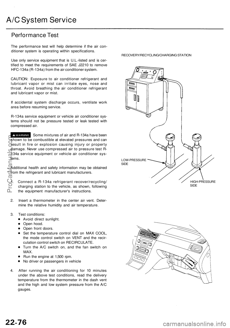
A/C Syste m Servic e
Performanc e Tes t
The performanc e tes t wil l hel p determin e i f th e ai r con -
ditione r syste m is operatin g withi n specifications .
Us e onl y servic e equipmen t tha t i s U.L.-liste d an d i s cer -
tifie d t o mee t th e requirement s o f SA E J221 0 t o remov e
HFC-134 a (R-134a ) fro m th e ai r conditione r system .
CAUTION : Exposur e t o ai r conditione r refrigeran t an d
lubrican t vapo r o r mis t ca n irritat e eyes , nos e an d
throat . Avoi d breathin g th e ai r conditione r refrigeran t
an d lubrican t vapo r o r mist .
I f accidenta l syste m discharg e occurs , ventilat e wor k
are a befor e resumin g service .
R-134 a servic e equipmen t o r vehicl e ai r conditione r sys -
tem s shoul d no t b e pressur e teste d o r lea k teste d wit h
compresse d air .
Som e mixture s o f ai r an d R-134 a hav e bee n
show n to b e combustibl e a t elevate d pressure s an d ca n
resul t i n fir e o r explosio n causin g injur y o r propert y
damage . Neve r us e compresse d ai r t o pressur e tes t R -
134 a servic e equipmen t o r vehicl e ai r conditione r sys -
tems .
Additiona l healt h an d safet y informatio n ma y b e obtaine d
fro m th e refrigeran t an d lubrican t manufacturers .
1 . Connec t a R-134 a refrigeran t recover/recycling /
chargin g statio n t o th e vehicle , a s shown , followin g
th e equipmen t manufacturer' s instructions .
2 . Inser t a thermomete r i n th e cente r ai r vent . Deter -
min e th e relativ e humidit y an d ai r temperature .
3 . Tes t conditions :
Avoi d direc t sunlight .
Ope n hood .
Ope n fron t doors .
Se t th e temperatur e contro l dia l o n MA X COOL ,
th e mod e contro l switc h o n VEN T an d th e recir -
culatio n contro l switc h o n RECIRCULATE.
Tur n th e A/ C switc h on , an d th e fa n switc h o n
MAX .
Run th e engin e a t 1,50 0 rpm .
N o drive r o r passenger s i n vehicl e
4 . Afte r runnin g th e ai r conditionin g fo r 1 0 minute s
unde r th e abov e tes t conditions , rea d th e deliver y
temperatur e fro m th e thermomete r i n th e das h ven t
an d th e hig h an d lo w syste m pressur e fro m th e A/ C
gauges .
RECOVERY/RECYCLING/CHARGIN G STATIO N
LOW-PRESSUR ESIDE
HIGH-PRESSUR ESIDE
ProCarManuals.com
Page 1511 of 1954
IGNITION CONTRO LMODULE (ICM )
UNDER-HOO D RELA YBOX B
DRIVER' S POWE R WINDO W MOTO R RELA Y B('98-0 1 models )• HOR N RELA Y('96-97 models )• POWE R WINDO W MASTE R SWITC H
RELA Y ('98-0 1 models )
CIGARETT E LIGHTE R RELA Y
• FRON T SEA T HEATE R RELA Y
('96-97 models )• DRIVER' S POWE R WINDO W MOTO R RELA Y A
('9 8-0 1 models )
SPAR K PLU G VOLTAG E
DETECTIO N MODUL E
DIMME R RELA Y •
AB S PUM P MOTO R RELA Y
('96-99 models )• VS A FAIL-SAF E RELA Y
('0 0-0 1 models )
• HEADLIGH T RELA Y
('96-98 models )• HEADLIGH T
LO W BEA M RELA Y
('99-01 models )
TAILLIGH T RELA Y
('9 6 - 9 8 models )
• HEADLIGH T HIG H BEA M RELA Y
('9 9-0 1 models )
UNDER-HOO
D
FUSE/RELAYBOX
ProCarManuals.com
Page 1513 of 1954
FRONT SEA T HEATE RRELAY ('99-0 1 models )
Wir e colors :
YEL/BLK , WHT/BL K
BL K an d BLK/RE D
CLIMATE
CONTRO LUNIT
MULTIPLE X CONTRO L UNI T(PASSENGER'S )
PCM
DAS H LIGHT S BRIGHTNES S
CONTROLLE R
FAN CONTRO L
UNIT
• BLOWE R MOTO R RELA Y
Wir e colors :
BLK/YEL , BLK ,
WH T an d RED/BL K
- BLOWE R MOTO R HIG H RELA Y
Wir e colors :
BLK/YEL , L G GR N
BLU/RE D an d BL K
• AB S CONTRO L UNI T
('96-9 9 models )• VS A CONVERTE R UNI T
('0 0-0 1 models )
ProCarManuals.com
Page 1514 of 1954
Relay an d Contro l Uni t Location s
Door, Floor , Roo f an d Rea r Bulkhea d
MULTIPLE X CONTRO L
UNI T (DOOR ) POWE R SEA T CONTRO L UNI T
NAVIGATIO NCONTROL UNI T
POWE R MIRRO R
CONTRO L UNI T
• AUTOMATI C LIGHTIN GCONTRO L UNI T (USA )• DAYTIM E RUNNIN G LIGHT SCONTRO L UNI T (Canada )TCS CONTRO L UNI T('96-9 9 models )FUEL PUM P RELA YWire colors : RED/WHT ,BLK/YEL, GR N an d YE L
ProCarManuals.com
Page 1517 of 1954

Power Relay s
Relay Tes t
NOTE : Se e pag e 23-13 2 fo r tur n signal/hazar d rela y inpu t
test .
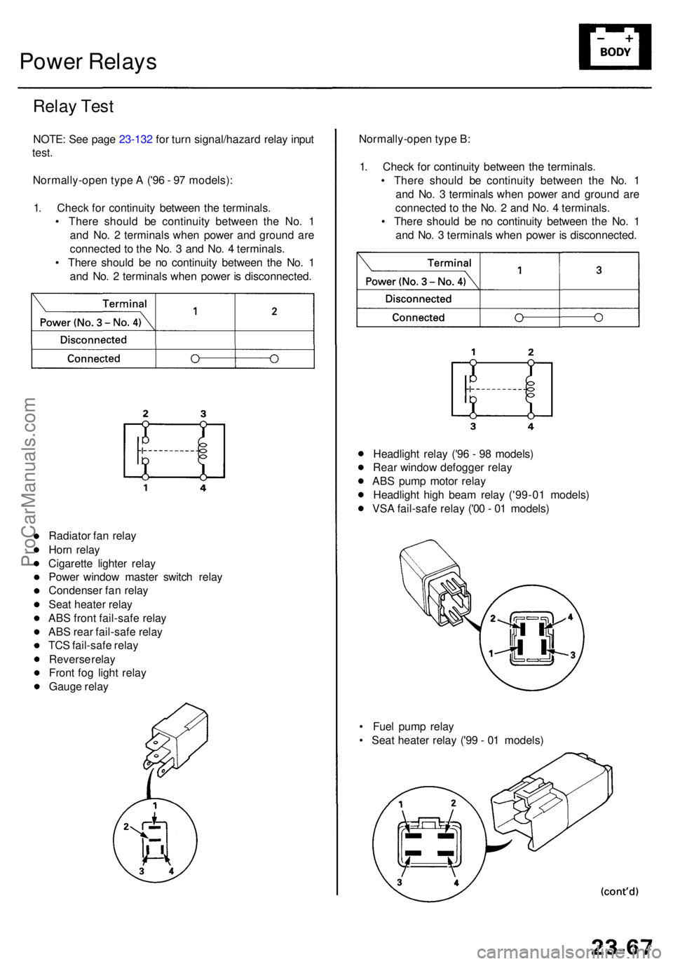
Normally-ope n typ e A ('9 6 - 9 7 models) :
1 . Chec k fo r continuit y betwee n th e terminals .
• Ther e shoul d b e continuit y betwee n th e No . 1
an d No . 2 terminal s whe n powe r an d groun d ar e
connecte d t o th e No . 3 an d No . 4 terminals .
• Ther e shoul d b e n o continuit y betwee n th e No . 1
an d No . 2 terminal s whe n powe r i s disconnected .Normally-ope
n typ e B :
1 . Chec k fo r continuit y betwee n th e terminals .
• Ther e shoul d b e continuit y betwee n th e No . 1
an d No . 3 terminal s whe n powe r an d groun d ar e
connecte d t o th e No . 2 an d No . 4 terminals .
• Ther e shoul d b e n o continuit y betwee n th e No . 1
an d No . 3 terminal s whe n powe r i s disconnected .
Radiato r fa n rela y
Hor n rela y
Cigarett e lighte r rela y
Powe r windo w maste r switc h rela y
Condense r fa n rela y
Sea t heate r rela y
AB S fron t fail-saf e rela y
AB S rea r fail-saf e rela y
TC S fail-saf e rela y
Revers e rela y
Fron t fo g ligh t rela y
Gaug e rela y
• Fue l pum p rela y
• Sea t heate r rela y ('9 9 - 0 1 models )
Headligh
t rela y ('9 6 - 9 8 models )
Rea r windo w defogge r rela y
AB S pum p moto r rela y
Headligh t hig h bea m rela y ('99-0 1 models )
VS A fail-saf e rela y ('0 0 - 0 1 models )
ProCarManuals.com
Page 1519 of 1954

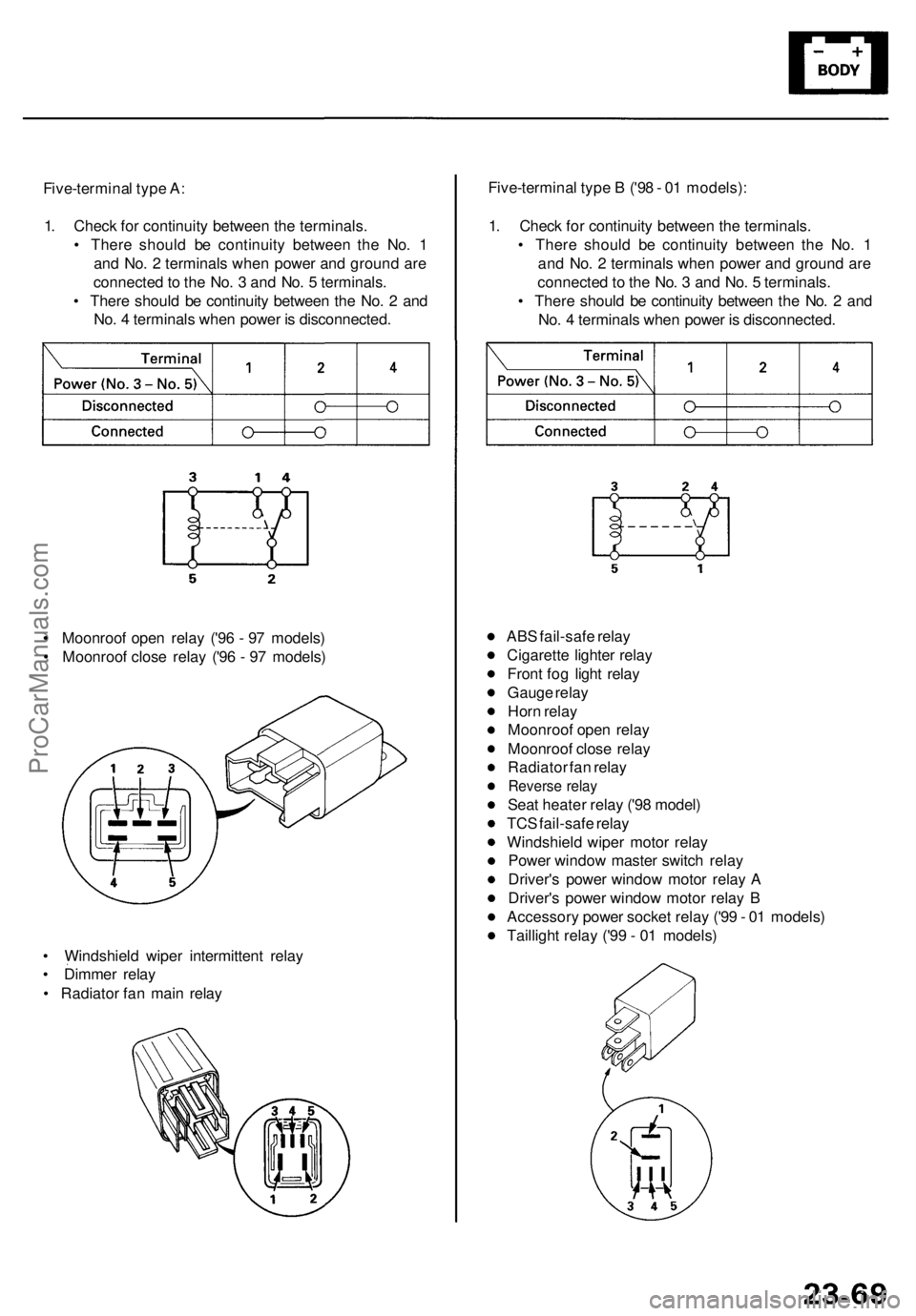
Five-terminal typ e A :
1 . Chec k fo r continuit y betwee n th e terminals .
• Ther e shoul d b e continuit y betwee n th e No . 1
an d No . 2 terminal s whe n powe r an d groun d ar e
connecte d to th e No . 3 an d No . 5 terminals .
• Ther e shoul d b e continuit y betwee n th e No . 2 an d
No . 4 terminal s whe n powe r i s disconnected .
• Moonroo f ope n rela y ('9 6 - 9 7 models )
• Moonroo f clos e rela y ('9 6 - 9 7 models )
• Windshiel d wipe r intermitten t rela y
• Dimme r rela y
• Radiato r fa n mai n rela y AB
S fail-saf e rela y
Cigarett e lighte r rela y
Fron t fo g ligh t rela y
Gaug e rela y
Hor n rela y
Moonroo f ope n rela y
Moonroo f clos e rela y
Radiato r fa n rela y
Revers e rela y
Seat heate r rela y ('9 8 model )
TC S fail-saf e rela y
Windshiel d wipe r moto r rela y
Powe r windo w maste r switc h rela y
Driver' s powe r windo w moto r rela y A
Driver' s powe r windo w moto r rela y B
Accessor y powe r socke t rela y ('9 9 - 0 1 models )
Tailligh t rela y ('9 9 - 0 1 models )
Five-termina
l typ e B ('9 8 - 0 1 models) :
1 . Chec k fo r continuit y betwee n th e terminals .
• Ther e shoul d b e continuit y betwee n th e No . 1
an d No . 2 terminal s whe n powe r an d groun d ar e
connecte d to th e No . 3 an d No . 5 terminals .
• Ther e shoul d b e continuit y betwee n th e No . 2 an d
No . 4 terminal s whe n powe r i s disconnected .
ProCarManuals.com
Page 1526 of 1954

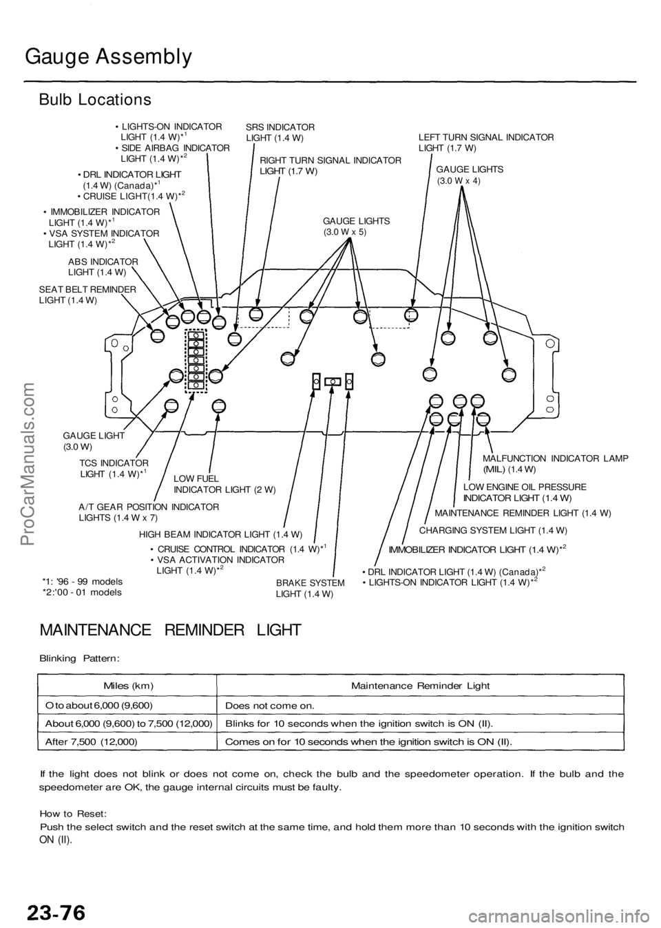
Gauge Assembl y
Bulb Location s
• LIGHTS-O N INDICATO R
LIGH T (1. 4 W)*1
• SID E AIRBA G INDICATO R
LIGH T (1. 4 W)*2
SR S INDICATO R
LIGH T (1. 4 W )
RIGH T TUR N SIGNA L INDICATO R
LIGHT (1. 7 W )
GAUG E LIGHT S(3.0 W x 5)
• DR L INDICATO R LIGH T(1.4 W ) (Canada)*1
• CRUIS E LIGHT(1. 4 W)*2
• IMMOBILIZE R INDICATO R
LIGH T (1. 4 W)*1
• VS A SYSTE M INDICATO R
LIGH T (1. 4 W)*2
AB S INDICATO R
LIGH T (1. 4 W )
SEA T BEL T REMINDE R
LIGH T (1. 4 W ) LEF
T TUR N SIGNA L INDICATO R
LIGH T (1. 7 W )
GAUG E LIGHT S
(3.0 W x 4)
MALFUNCTIO N INDICATO R LAM P(MIL) (1.4 W)
LO W ENGIN E OI L PRESSUR EINDICATOR LIGH T (1. 4 W )
MAINTENANC E REMINDE R LIGH T (1. 4 W )
CHARGIN G SYSTE M LIGH T (1. 4 W )
IMMOBILIZE R INDICATO R LIGH T (1. 4 W)*2
• DR L INDICATO R LIGH T (1. 4 W ) (Canada)*2
• LIGHTS-O N INDICATO R LIGH T (1. 4 W)*2BRAK E SYSTE MLIGHT (1. 4 W )
A/
T GEA R POSITIO N INDICATO R
LIGHT S (1. 4 W x 7) LO
W FUE L
INDICATO R LIGH T ( 2 W )
TC
S INDICATO R
LIGH T (1. 4 W)*
1
GAUG E LIGH T(3.0 W )
HIG H BEA M INDICATO R LIGH T (1. 4 W )
• CRUIS E CONTRO L INDICATO R (1. 4 W)*1
• VS A ACTIVATIO N INDICATO R
LIGH T (1. 4 W)*2
*1 : '9 6 - 9 9 model s*2:'00 - 0 1 model s
MAINTENANC E REMINDE R LIGH T
Blinking Pattern :
Miles (km ) Maintenance Reminde r Ligh t
O to abou t 6,00 0 (9,600 )
Does no t com e on .
Abou t 6,00 0 (9,600 ) t o 7,50 0 (12,000 )Blink s fo r 1 0 second s whe n th e ignitio n switc h is O N (II) .
Come s o n fo r 1 0 second s whe n th e ignitio n switc h is O N (II) .Afte r 7,50 0 (12,000 )
I f th e ligh t doe s no t blin k o r doe s no t com e on , chec k th e bul b an d th e speedomete r operation . I f th e bul b an d th e
speedomete r ar e OK , th e gaug e interna l circuit s mus t b e faulty .
How to Reset :
Push th e selec t switc h an d th e rese t switc h a t th e sam e time , an d hol d the m mor e tha n 1 0 second s wit h th e ignitio n switc h
ON (II) .
ProCarManuals.com