1996 ACURA RL KA9 light
[x] Cancel search: lightPage 1561 of 1954
Interior Light s
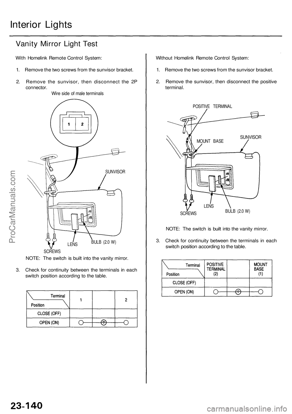
Vanity Mirro r Ligh t Tes t
With Homelin k Remot e Contro l System :
1 . Remov e th e tw o screw s fro m th e sunviso r bracket .
2 . Remov e th e sunvisor , the n disconnec t th e 2 P
connector .
Wire sid e o f mal e terminal s
NOTE: Th e switc h is buil t int o th e vanit y mirror .
3 . Chec k fo r continuit y betwee n th e terminal s i n eac h
switc h positio n accordin g t o th e table . Withou
t Homelin k Remot e Contro l System :
1 . Remov e th e tw o screw s fro m th e sunviso r bracket .
2 . Remov e th e sunvisor , the n disconnec t th e positiv e
terminal .
POSITIV E TERMINA L
SUNVISORMOUNT BAS E
SCREW S
SUNVISO
R
LENS
BULB (2. 0 W )
NOTE : Th e switc h is buil t int o th e vanit y mirror .
3 . Chec k fo r continuit y betwee n th e terminal s i n eac h
switc h positio n accordin g to th e table .BULB (2. 0 W )
LEN S
SCREW S
ProCarManuals.com
Page 1572 of 1954
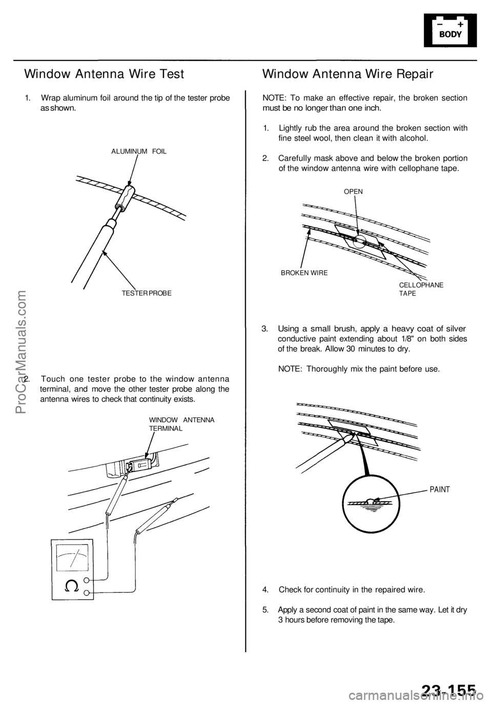
Window Antenn a Wir e Tes t
1. Wra p aluminu m foi l aroun d th e ti p o f th e teste r prob e
as shown .
ALUMINU M FOI L
TESTE R PROB E
2. Touc h on e teste r prob e t o th e windo w antenn a
terminal , an d mov e th e othe r teste r prob e alon g th e
antenn a wire s t o chec k tha t continuit y exists .
WINDO W ANTENN A
TERMINA L
Window Antenn a Wir e Repai r
NOTE: T o mak e a n effectiv e repair , th e broke n sectio n
must b e n o longe r tha n on e inch .
1. Lightl y ru b th e are a aroun d th e broke n sectio n wit h
fin e stee l wool , the n clea n it wit h alcohol .
2 . Carefull y mas k abov e an d belo w th e broke n portio n
o f th e windo w antenn a wir e wit h cellophan e tape .
4 . Chec k fo r continuit y i n th e repaire d wire .
5 . Appl y a secon d coa t o f pain t i n th e sam e way . Le t i t dr y
3 hour s befor e removin g th e tape .
PAIN T
3. Usin g a smal l brush , appl y a heav y coa t o f silve r
conductiv e pain t extendin g abou t 1/8 " o n bot h side s
o f th e break . Allo w 3 0 minute s t o dry .
NOTE : Thoroughl y mi x th e pain t befor e use .
BROKE N WIR E
CELLOPHAN ETAPE
OPE N
ProCarManuals.com
Page 1574 of 1954
Cigarette Lighte r
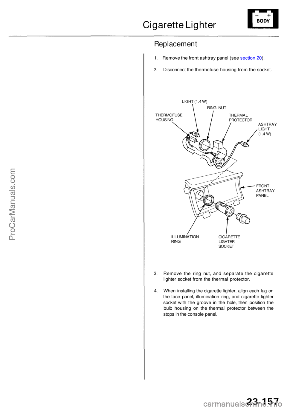
Replacemen t
1. Remov e th e fron t ashtra y pane l (se e sectio n 20 ).
2 . Disconnec t th e thermofus e housin g fro m th e socket .
3 . Remov e th e rin g nut , an d separat e th e cigarett e
lighte r socke t fro m th e therma l protector .
4 . Whe n installin g th e cigarett e lighter , alig n eac h lu g o n
th e fac e panel , illuminatio n ring , an d cigarette lighter
socke t wit h th e groov e i n th e hole , the n positio n th e
bul b housin g o n th e therma l protecto r betwee n th e
stop s in th e consol e panel .
ILLUMINATIO N
RIN GCIGARETT ELIGHTERSOCKET
FRONTASHTRA YPANEL
ASHTRA YLIGHT(1.4 W )
THERMA LPROTECTO R
RING NU T
LIGH
T (1. 4 W )
THERMOFUS E
HOUSIN G
ProCarManuals.com
Page 1588 of 1954
Automatic Insid e Dimmin g Mirro r
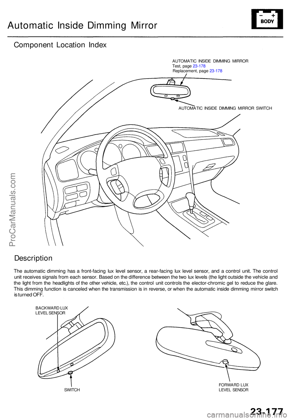
Componen t Locatio n Inde x
AUTOMATI C INSID E DIMMIN G MIRRO R
Test , pag e 23-17 8
Replacement , pag e 23-17 8
AUTOMATI C INSID E DIMMIN G MIRRO R SWITC H
Descriptio n
The automati c dimmin g ha s a front-facin g lu x leve l sensor , a rear-facin g lu x leve l sensor , an d a contro l unit . Th e contro l
uni t receive s signal s fro m eac h sensor . Base d o n th e differenc e betwee n th e tw o lu x level s (th e ligh t outsid e th e vehicl e an d
th e ligh t fro m th e headlight s o f th e othe r vehicle , etc.) , th e contro l uni t control s th e elector-chromi c ge l t o reduc e th e glare .
Thi s dimmin g functio n is cancele d whe n th e transmissio n is in reverse , o r whe n th e automati c insid e dimmin g mirro r switc h
i s turne d OFF .
BACKWAR D LU XLEVE L SENSO R
SWITC H
FORWAR D LU XLEVE L SENSO R
ProCarManuals.com
Page 1593 of 1954
Description
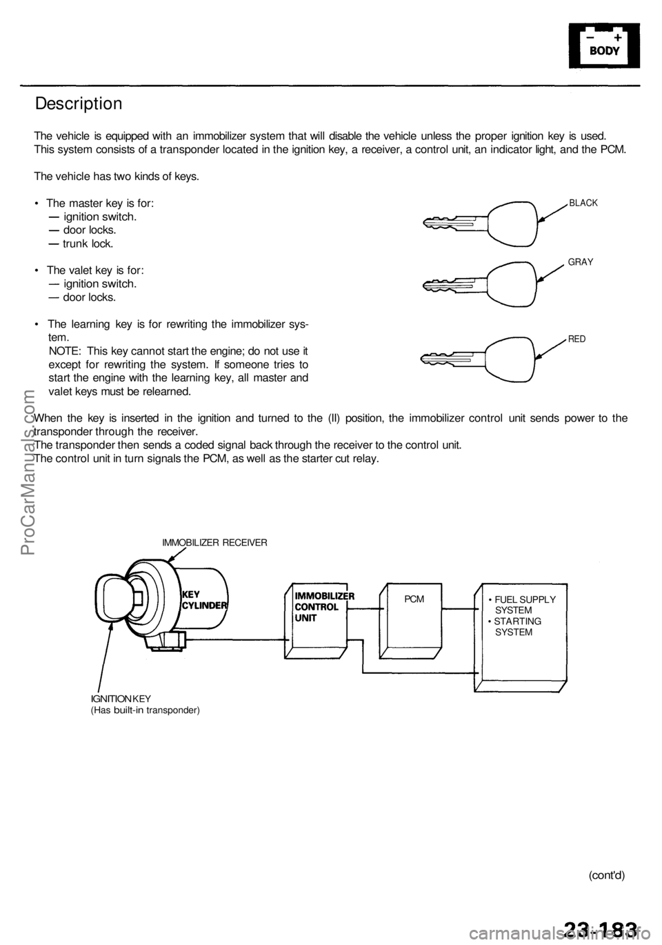
The vehicl e is equippe d wit h a n immobilize r syste m tha t wil l disabl e th e vehicl e unles s th e prope r ignitio n ke y i s used .
Thi s syste m consist s o f a transponde r locate d in th e ignitio n key , a receiver , a contro l unit , a n indicato r light , an d th e PCM .
Th e vehicl e ha s tw o kind s o f keys .
• Th e maste r ke y i s for :
ignitio n switch .
door locks .
trunk lock .
• Th e vale t ke y i s for :
ignitio n switch .
door locks .
• Th e learnin g ke y i s fo r rewritin g th e immobilize r sys -
tem.
NOTE : Thi s ke y canno t star t th e engine ; d o no t us e it
excep t fo r rewritin g th e system . I f someon e trie s t o
star t th e engin e wit h th e learnin g key , al l maste r an d
vale t key s mus t b e relearned .
Whe n th e ke y i s inserte d i n th e ignitio n an d turne d t o th e (II ) position , th e immobilize r contro l uni t send s powe r t o th e
transponde r throug h th e receiver .
Th e transponde r the n send s a code d signa l bac k throug h th e receive r t o th e contro l unit .
Th e contro l uni t i n tur n signal s th e PCM , a s wel l a s th e starte r cu t relay .
IMMOBILIZE R RECEIVE R
IGNITION KEY(Ha s built-i n transponder ) •
FUE L SUPPL Y
SYSTE M
• STARTIN G
SYSTEM
PCM
BLAC K
GRAY
RED
(cont'd )
ProCarManuals.com
Page 1594 of 1954
Immobilizer Syste m
Descriptio n (cont'd )
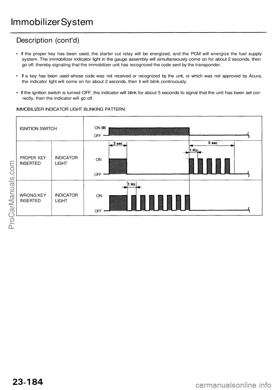
• I f th e prope r ke y ha s bee n used , th e starte r cu t rela y wil l b e energized , an d th e PC M wil l energiz e th e fue l suppl y
system . Th e immobilize r indicato r ligh t i n th e gaug e assembl y wil l simultaneousl y com e o n fo r abou t 2 seconds , the n
go off , thereb y signalin g tha t th e immobilize r uni t ha s recognize d th e cod e sen t b y th e transponder .
• I f a ke y ha s bee n use d whos e cod e wa s no t receive d o r recognize d b y th e unit , o r whic h wa s no t approve d b y Acura ,
th e indicato r ligh t wil l com e o n fo r abou t 2 seconds , the n it wil l blin k continuously .
• I f th e ignitio n switc h is turne d OFF , th e indicato r wil l blin k fo r abou t 5 second s to signa l tha t th e uni t ha s bee n se t cor -
rectly , the n th e indicato r wil l g o off .
IMMOBILIZE R INDICATO R LIGH T BLINKIN G PATTERN :
WRONG KE Y
INSERTE D
PROPER KE Y
INSERTE D
IGNITION SWITC H
INDICATO R
LIGHT
INDICATO R
LIGHT
ON
OF F
ON
OF F
ON
OF F
ProCarManuals.com
Page 1595 of 1954
Problems an d Replacemen t Part s
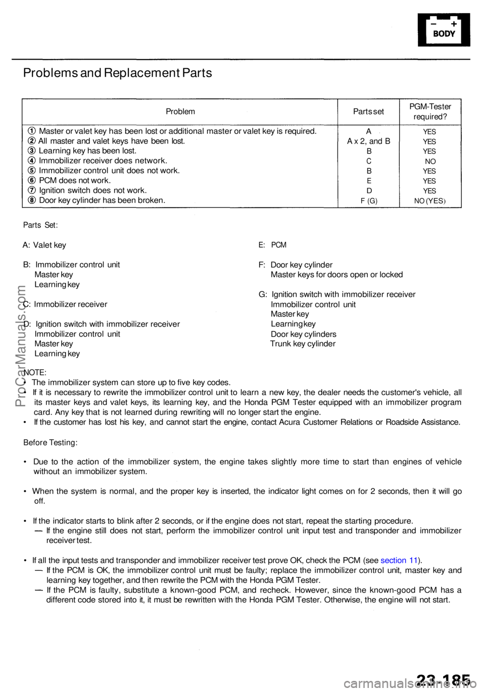
Proble m
Master o r vale t ke y ha s bee n los t o r additiona l maste r o r vale t ke y is required .
Al l maste r an d vale t key s hav e bee n lost .
Learnin g ke y ha s bee n lost .
Immobilize r receive r doe s network .
Immobilize r contro l uni t doe s no t work .
PC M doe s no t work .
Ignitio n switc h doe s no t work .
Doo r ke y cylinde r ha s bee n broken . Part
s se t
PGM-Teste r
required?
YES
YES
YE S
NO
YE S
YE S
YES
NO (YES )
A
A x 2 , an d B
B
C
B
E
D
F (G )
Part s Set :
A: Vale t ke y
B : Immobilize r contro l uni t
Maste r ke y
Learnin g ke y
C : Immobilize r receive r
D : Ignitio n switc h wit h immobilize r receive r
Immobilize r contro l uni t
Maste r ke y
Learnin g ke yE: PC M
F: Doo r ke y cylinde r
Maste r key s fo r door s ope n o r locke d
G : Ignitio n switc h wit h immobilize r receive r
Immobilize r contro l uni t
Maste r ke y
Learnin g ke y
Doo r ke y cylinder s
Trun k ke y cylinde r
NOTE:
• Th e immobilize r syste m ca n stor e u p to fiv e ke y codes .
• I f i t i s necessar y t o rewrit e th e immobilize r contro l uni t t o lear n a ne w key , th e deale r need s th e customer' s vehicle , al l
it s maste r key s an d vale t keys , it s learnin g key , an d th e Hond a PG M Teste r equippe d wit h a n immobilize r progra m
card . An y ke y tha t i s no t learne d durin g rewritin g wil l n o longe r star t th e engine .
• I f th e custome r ha s los t hi s key , an d canno t star t th e engine , contac t Acur a Custome r Relation s o r Roadsid e Assistance .
Before Testing :
• Du e t o th e actio n o f th e immobilize r system , th e engin e take s slightl y mor e tim e t o star t tha n engine s o f vehicl e
withou t a n immobilize r system .
• Whe n th e syste m is normal , an d th e prope r ke y i s inserted , th e indicato r ligh t come s o n fo r 2 seconds , the n i t wil l g o
off .
• I f th e indicato r start s t o blin k afte r 2 seconds , o r i f th e engin e doe s no t start , repea t th e startin g procedure .
If th e engin e stil l doe s no t start , perfor m th e immobilize r contro l uni t inpu t tes t an d transponde r an d immobilize r
receive r test .
• I f al l th e inpu t test s an d transponde r an d immobilize r receive r tes t prov e OK , chec k th e PC M (se e sectio n 11 ).
I f th e PC M is OK , th e immobilize r contro l uni t mus t b e faulty ; replac e th e immobilize r contro l unit , maste r ke y an d
learnin g ke y together , an d the n rewrit e th e PC M wit h th e Hond a PG M Tester .
If th e PC M is faulty , substitut e a known-goo d PCM , an d recheck . However , sinc e th e known-goo d PC M ha s a
differen t cod e store d int o it , i t mus t b e rewritte n wit h th e Hond a PG M Tester . Otherwise , th e engin e wil l no t start .
ProCarManuals.com
Page 1645 of 1954
System Function s
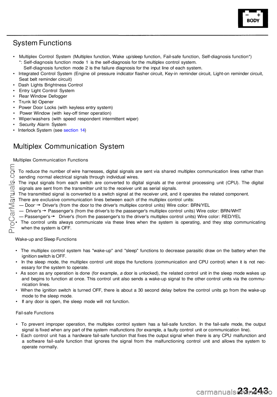
• Multiple x Contro l Syste m (Multiple x function , Wak e up/slee p function , Fail-saf e function , Self-diagnosi s function* )
* : Self-diagnosi s functio n mod e 1 is th e self-diagnosi s fo r th e multiple x contro l system .
Self-diagnosi s functio n mod e 2 is th e failur e diagnosi s fo r th e inpu t lin e o f eac h system .
• Integrate d Contro l Syste m (Engin e oi l pressur e indicato r flashe r circuit , Key-i n reminde r circuit , Light-o n reminde r circuit ,
Sea t bel t reminde r circuit )
• Das h Light s Brightnes s Contro l
• Entr y Ligh t Contro l Syste m
• Rea r Windo w Defogge r
• Trun k li d Opene r
• Powe r Doo r Lock s (wit h keyles s entr y system )
• Powe r Windo w (wit h key-of f timer operation )
• Wiper/washer s (wit h spee d responden t intermitten t wiper )
• Securit y Alar m Syste m
• Interloc k Syste m (se e sectio n 14 )
Multiple x Communicatio n Syste m
Multiple x Communicatio n Function s
• T o reduc e th e numbe r o f wir e harnesses , digita l signal s ar e sen t vi a share d multiple x communicatio n line s rather than
sendin g norma l electrica l signal s throug h individua l wires .
• Th e inpu t signal s fro m eac h switc h ar e converte d t o digita l signal s a t th e centra l processin g uni t (CPU) . Th e digita l
signal s ar e sen t fro m th e transmitte r uni t t o th e receive r uni t a s seria l signals .
• Th e transmitte d signa l i s converte d t o a switc h signa l a t th e receive r unit , an d it operate s th e relate d component .
• Ther e ar e exclusiv e communicatio n line s betwee n eac h o f th e multiple x contro l units :
Door Driver' s (fro m th e doo r t o th e driver' s multiple x contro l units ) Wir e color : BRN/YE L
Driver's Passenger' s (fro m th e driver' s t o th e passenger' s multiple x contro l units ) Wir e color : BRN/WH T
Passenger' s Driver' s (fro m th e passenger' s t o th e driver' s multiple x contro l units ) Wir e color : RED/YE L
• Th e contro l unit s alway s communicat e vi a thes e line s whe n th e syste m is operating , an d the y sto p communicatin g
whe n th e syste m is OFF .
Wake-u p an d Slee p Function s
• Th e multiple x contro l syste m ha s "wake-up " an d "sleep " function s t o decreas e parasiti c dra w o n th e batter y whe n th e
ignitio n switc h is OFF .
• I n th e slee p mode , th e multiple x contro l uni t stop s th e function s (communicatio n an d CP U control ) whe n i t i s no t nec -
essar y fo r th e syste m to operate .
• A s soo n a s an y operatio n i s don e (fo r example , a doo r i s unlocked) , th e relate d contro l uni t i n th e slee p mod e wake s u p
an d begin s t o functio n a t once . Thi s contro l uni t als o send s a wake-u p signa l t o th e othe r contro l unit s vi a th e commu -
nicatio n lines .
• Whe n th e ignitio n switc h i s turne d OFF , ther e i s abou t a 30 secon d dela y befor e th e contro l unit s g o fro m th e wake-u p
mod e t o th e slee p mode .
• I f an y doo r i s open , th e slee p mod e wil l no t function .
Fail-safe Function s
• T o preven t imprope r operation , th e multiple x contro l syste m ha s a fail-saf e function . I n th e fail-saf e mode , th e outpu t
signa l i s fixe d whe n an y par t o f th e syste m malfunction s (fo r example , a fault y contro l uni t o r communicatio n line) .
• Eac h contro l uni t ha s a hardwar e fail-saf e functio n tha t fixe s th e outpu t signa l whe n ther e i s an y CP U malfunctio n an d
a softwar e fail-saf e functio n tha t ignore s th e signa l fro m th e malfunctionin g contro l uni t an d allow s th e syste m to
operat e normally .
ProCarManuals.com