Page 1199 of 1954
Diagnostic Trouble Code (DTC)
DTC Erasure
1. Press the parking brake pedal.
2. Push and hold the TCS switch, then turn the ignition switch ON (II).
3. Hold the TCS switch pushed for 4 to 6 seconds, then release the TCS switch.
4. After 3 seconds, the TCS indicator light should go off and blink 2 times, then stay on. This means that the DTC is
erased.
NOTE:
Always follow these steps exactly. If you connect the SCS service connector and/or release the parking brake pedal dur-
ing these steps, the DTC will not be erased.
If the TCS indicator light blinks repeatedly, replace the TCS control unit.
Standard Indication Pattern
Abnormal Indication Pattern
Light blinks repeatedlyProCarManuals.com
Page 1201 of 1954
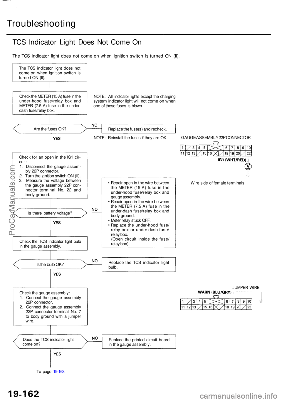
Troubleshooting
TCS Indicato r Ligh t Doe s No t Com e O n
Th e TC S indicato r ligh t doe s no t com e o n whe n ignitio n switc h i s turne d O N (II) .
The TC S indicato r ligh t doe s no t
com e o n whe n ignitio n switc h is
turne d O N (II) .
Chec k th e METE R (1 5 A ) fus e in th e
under-hoo d fuse/rela y bo x an d
METE R (7. 5 A ) fus e i n th e under -
das h fuse/rela y box .
Ar e th e fuse s OK ?
Chec k fo r a n ope n in th e IG 1 cir -
cuit :
1 . Disconnec t th e gaug e assem -
bl y 22 P connector .
2. Tur n th e ignitio n switc h O N (II) .3. Measur e th e voltag e betwee n
th e gaug e assembl y 22 P con -
necto r termina l No . 2 2 an d
body ground .
Is ther e batter y voltage ?
Is th e bul b OK ?
Chec k th e gaug e assembly :
1 . Connec t th e gaug e assembl y
22 P connector .
2 . Connec t th e gaug e assembl y
22 P connecto r termina l No . 7
t o bod y groun d wit h a jumpe r
wire .
Doe s th e TC S indicato r ligh t
com e on ?
T o pag e 19-16 3 NOTE
: Al l indicato r light s excep t th e chargin g
system indicato r ligh t wil l no t com e o n whe none o f thes e fuse s i s blown .
Replac e th e fuse(s ) an d recheck .
NOTE : Reinstal l th e fuse s if the y ar e OK . GAUG
E ASSEMBL Y 22 P CONNECTO R
Repai r ope n in th e wir e betwee n
th e METE R (1 5 A ) fus e i n th e
under-hoo d fuse/rela y bo x an d
gaug e assembly .
Repai r ope n in th e wir e betwee n
th e METE R (7. 5 A ) fus e i n th e
under-das h fuse/rela y bo x an d
bod y ground .
Mete r rela y stuc k OFF .
Replac e th e under-hoo d fuse /
relay bo x o r under-das h fuse /relay box .
(Ope n circui t insid e th e fuse /
rela y box ) Wir
e sid e o f femal e terminal s
Replac e th e TC S indicato r ligh t
bulb.
JUMPE R WIR E
Replac e th e printe d circui t boar d
i n th e gaug e assembly .
Chec
k th e TC S indicato r ligh t bul b
i n th e gaug e assembly .
ProCarManuals.com
Page 1206 of 1954
From pag e 19-16 6
Chec k th e brak e flui d leve l switch :
Disconnec t th e brak e flui d leve lswitch connectors .
Doe s th e brak e syste m ligh t g o off ? Replac
e th e brak e flui d leve l
switch . (Switc h stuc k ON )
Chec k th e parkin g brak e switc h
(se e pag e 19-8) .
Is th e switc h OK ?Replac e th e parkin g brak e switch .
(Switc h stuc k ON )
Chec k fo r a shor t t o bod y groun d
i n th e PAR K circuit :
Disconnec t th e TC S contro l uni tconnector .
Doe s th e brak e syste m ligh t
g o off ? Replac
e th e TC S contro l unit .
(Shor t t o bod y groun d insid e th e
unit )
Repai r shor t t o bod y groun d i n
th e wir e betwee n th e brak e sys -
te m light , parkin g brak e switc h
an d brak e flui d leve l switch .
ProCarManuals.com
Page 1212 of 1954
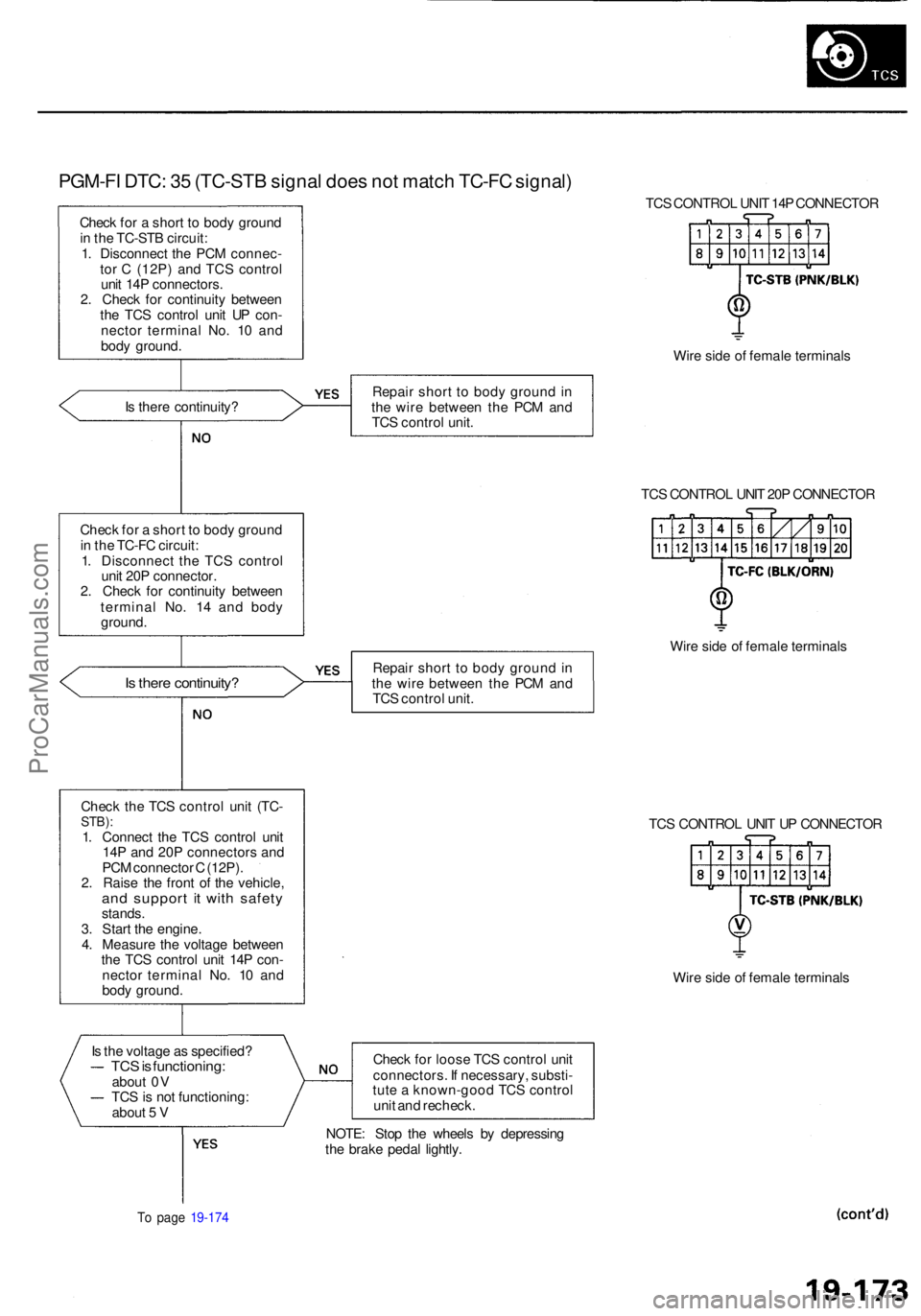
PGM-FI DTC : 3 5 (TC-ST B signa l doe s no t matc h TC-F C signal )
Check fo r a shor t t o bod y groun d
i n th e TC-ST B circuit :
1 . Disconnec t th e PC M connec -
to r C (12P ) an d TC S contro l
uni t 14 P connectors .
2 . Chec k fo r continuit y betwee n
th e TC S contro l uni t U P con -
necto r termina l No . 1 0 an d
bod y ground . TC
S CONTRO L UNI T 14 P CONNECTO R
Wir e sid e o f femal e terminal s
I s ther e continuity ? Repai
r shor t t o bod y groun d in
th e wir e betwee n th e PC M an d
TC S contro l unit .
TCS CONTRO L UNI T 20 P CONNECTO R
Chec k fo r a shor t t o bod y groun d
i n th e TC-F C circuit :
1 . Disconnec t th e TC S contro l
uni t 20 P connector .
2 . Chec k fo r continuit y betwee n
termina l No . 1 4 an d bod y
ground .
Is ther e continuity ?Repair shor t t o bod y groun d in
th e wir e betwee n th e PC M an d
TC S contro l unit . Wir
e sid e o f femal e terminal s
Chec k th e TC S contro l uni t (TC -
STB) :1. Connec t th e TC S contro l uni t
14 P an d 20 P connector s an d
PC M connecto r C (12P) .
2 . Rais e th e fron t o f th e vehicle ,
and suppor t i t wit h safet ystands.
3 . Star t th e engine .
4 . Measur e th e voltag e betwee n
th e TC S contro l uni t 14 P con -
necto r termina l No . 1 0 an d
bod y ground . TC
S CONTRO L UNI T U P CONNECTO R
Wir e sid e o f femal e terminal s
I s th e voltag e a s specified ?
TCS is functioning :about 0 V
TC S is no t functioning :
abou t 5 V Chec
k fo r loos e TC S contro l uni t
connectors . I f necessary , substi -
tut e a known-goo d TC S contro l
uni t an d recheck .
To pag e 19-17 4
NOTE : Sto p th e wheel s b y depressin g
th e brak e peda l lightly .
ProCarManuals.com
Page 1213 of 1954
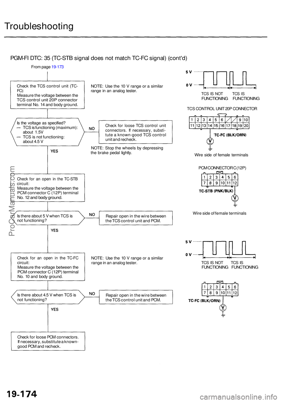
Troubleshooting
PGM-FI DTC : 3 5 (TC-ST B signa l doe s no t matc h TC-F C signal ) (cont'd )
From pag e 19-17 3
Chec k th e TC S contro l uni t (TC -
FC):Measur e th e voltag e betwee n th eTC S contro l uni t 20 P connecto rterminal No . 1 4 an d bod y ground .NOTE
: Us e th e 1 0 V rang e o r a simila r
rang e in a n analo g tester .
TCS IS NO T TC S ISFUNCTIONIN G FUNCTIONIN G
TCS CONTRO L UNI T 20 P CONNECTO R
Check fo r loos e TC S contro l uni tconnectors . I f necessary , substi -tute a known-goo d TC S contro l
uni t an d recheck .
NOTE : Sto p th e wheel s b y depressin g
th e brak e peda l lightly .
Check fo r a n ope n i n th e TC-ST Bcircuit:Measur e th e voltag e betwee n th e
PC M connecto r C (12P ) termina l
No. 1 2 an d bod y ground .
Wire sid e o f femal e terminal s
PC M CONNECTO R C (12P )
I s ther e abou t 5 V whe n TC S is
no t functioning ? Repai
r ope n in th e wir e betwee n
th e TC S contro l uni t an d PCM . Wir
e sid e o f femal e terminal s
Check fo r a n ope n i n th e TC-F Ccircuit :
Measur e th e voltag e betwee n th e
PC M connecto r C (12P ) termina lNo. 1 0 an d bod y ground . NOTE
: Us e th e 1 0 V rang e o r a simila r
rang e in a n analo g tester .
TCS IS NO T TC S ISFUNCTIONIN G FUNCTIONIN G
I s ther e abou t 4. 5 V whe n TC S is
no t functioning ? Repai
r ope n in th e wir e betwee n
th e TC S contro l uni t an d PCM .
Chec k fo r loos e PC M connectors .
I f necessary , substitut e a known -
goo d PC M an d recheck .
TC
S is functionin g (maximum) :
abou t 1.5 V
TC S is no t functioning :
abou t 4. 5 V
I
s th e voltag e a s specified ?
ProCarManuals.com
Page 1217 of 1954
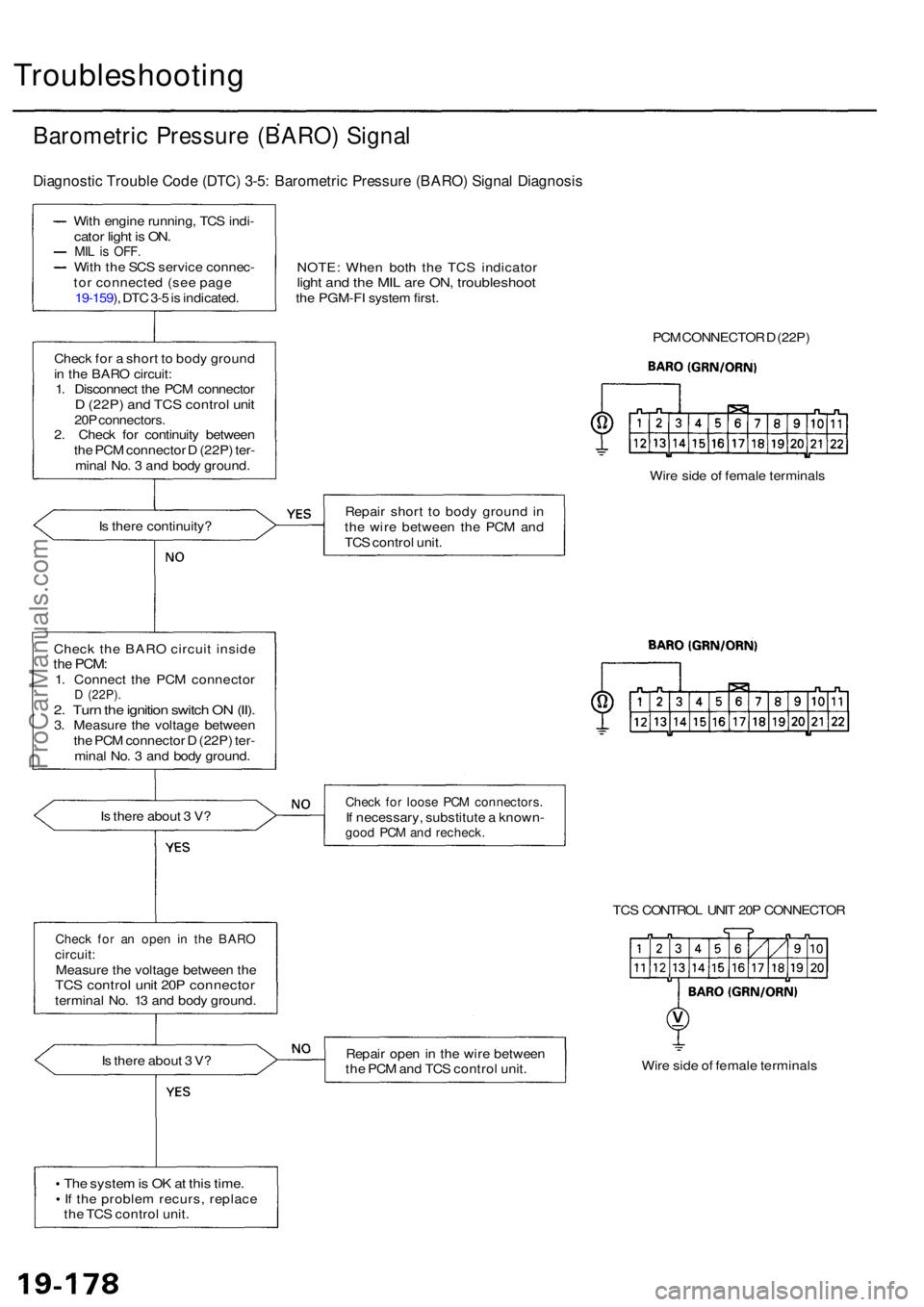
Troubleshooting
Barometric Pressur e (BARO ) Signa l
Diagnosti c Troubl e Cod e (DTC ) 3-5 : Barometri c Pressur e (BARO ) Signa l Diagnosi s
With engin e running , TC S indi -cato r ligh t i s ON .MIL is OFF .With th e SC S servic e connec -
to r connecte d (se e pag e
19-159 ), DT C 3- 5 is indicated .
Chec k fo r a shor t t o bod y groun d
i n th e BAR O circuit :
1 . Disconnec t th e PC M connecto r
D (22P ) an d TC S contro l uni t20P connectors .2. Chec k fo r continuit y betwee n
th e PC M connecto r D (22P ) ter -
mina l No . 3 an d bod y ground .
I s ther e continuity ?
Chec k th e BAR O circui t insid e
the PCM :1. Connec t th e PC M connecto rD (22P) .2. Tur n th e ignitio n switc h O N (II) .3. Measur e th e voltag e betwee n
th e PC M connecto r D (22P ) ter -
mina l No . 3 an d bod y ground .
I s ther e abou t 3 V ?
Chec k fo r a n ope n i n th e BAR Ocircuit :Measur e th e voltag e betwee n th eTC S contro l uni t 20 P connecto rterminal No . 1 3 an d bod y ground .
I s ther e abou t 3 V ?
Th e syste m is O K at thi s time .If th e proble m recurs , replac e
th e TC S contro l unit . NOTE
: Whe n bot h th e TC S indicato r
light an d th e MI L ar e ON , troubleshoo tthe PGM-F I syste m first .
PCM CONNECTO R D (22P )
Wir e sid e o f femal e terminal s
Repai r shor t t o bod y groun d in
th e wir e betwee n th e PC M an d
TC S contro l unit .
Chec k fo r loos e PC M connectors .If necessary , substitut e a known -good PC M an d recheck .
TCS CONTRO L UNI T 20 P CONNECTO R
Repai r ope n in th e wir e betwee n
th e PC M an d TC S contro l unit . Wir
e sid e o f femal e terminal s
ProCarManuals.com
Page 1218 of 1954
Throttle Positio n Senso r (TPS ) Signa l
Diagnosti c Troubl e Cod e (DTC ) 3-6 : Throttl e Positio n Senso r (TPS ) Signa l Diagnosi s
With engin e running , TC S
indicato r ligh t i s ON .
MIL is OFF .With th e SC S servic e connec -
to r connecte d (se e pag e
19-159 ), DT C 3- 6 is indicated .NOTE
: Whe n bot h th e TC S indicato rlight an d th e MI L ar e ON , trouble -shoot th e PGM-F I syste m first .
TCS CONTRO L UNI T 14 P CONNECTO R
Check fo r a n ope n i n th e TP S cir -cuit :Measur e th e voltag e betwee n th e
TC S contro l uni t 14 P connecto r
termina l No . 1 4 an d bod y ground .
I s th e voltag e a s specified ?
Full y closed : abou t 0. 5 V
Full y open : abou t 4. 5 V Repai
r ope n in th e wir e betwee n
th e PC M an d TC S contro l unit . Wir
e sid e o f femal e terminal s
Th e syste m is O K at thi s time .
I f th e proble m recurs , replac e
th e TC S contro l unit .
ProCarManuals.com
Page 1219 of 1954
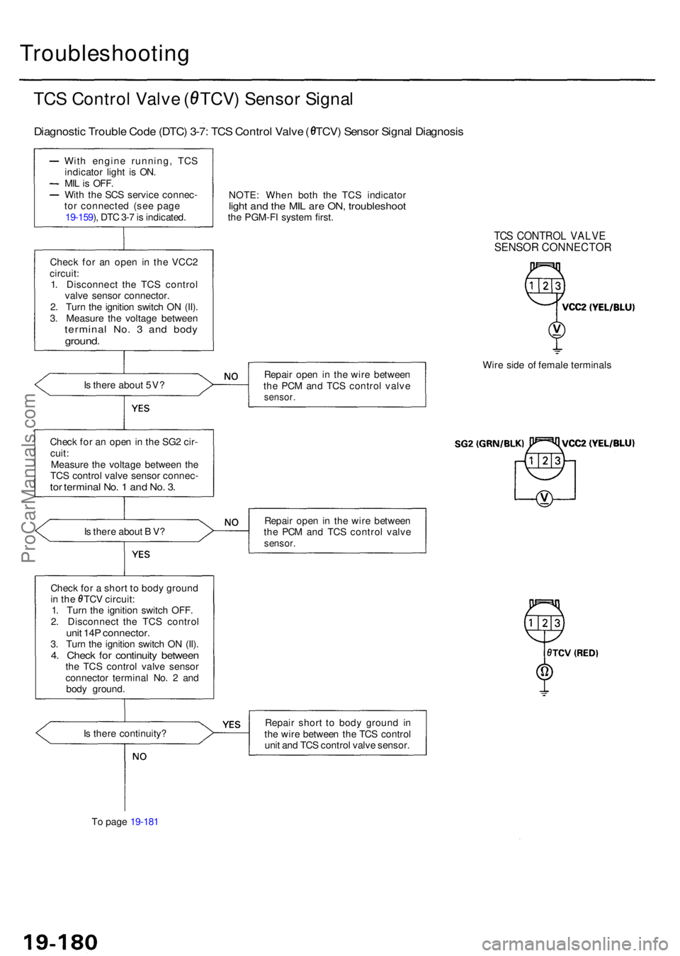
Troubleshooting
TCS Contro l Valv e ( TCV ) Senso r Signa l
Diagnosti c Troubl e Cod e (DTC ) 3-7 : TC S Contro l Valv e ( TCV ) Senso r Signa l Diagnosi s
With engin e running , TC S
indicato r ligh t i s ON .
MIL is OFF .With th e SC S servic e connec -
to r connecte d (se e pag e
19-159 ), DT C 3- 7 is indicated .
Chec k fo r a n ope n i n th e VCC 2
circuit :
1 . Disconnec t th e TC S contro l
valv e senso r connector .
2 . Tur n th e ignitio n switc h O N (II) .
3 . Measur e th e voltag e betwee n
termina l No . 3 an d bod yground .
Is ther e abou t 5V ?
Chec k fo r a n ope n in th e SG 2 cir -
cuit :
Measur e th e voltag e betwee n th e
TC S control valve senso r connec -
tor termina l No . 1 an d No . 3 .
Is ther e abou t B V ?
Chec k fo r a shor t t o bod y groun d
in th e TC V circuit :
1 . Tur n th e ignitio n switc h OFF .
2 . Disconnec t th e TC S contro l
unit 14 P connector .3. Tur n th e ignitio n switc h O N (II) .4. Chec k fo r continuit y betwee nthe TC S contro l valv e sensor
connecto r termina l No . 2 an d
bod y ground . NOTE
: Whe n bot h th e TC S indicato r
light an d th e MI L ar e ON , troubleshoo tthe PGM-F I syste m first .
TCS CONTRO L VALV ESENSO R CONNECTO R
Repair ope n i n th e wir e betwee n
th e PC M an d TC S contro l valv e
sensor .
Wire sid e o f femal e terminal s
Repai r ope n in th e wir e betwee n
th e PC M an d TC S contro l valv e
sensor .
Is ther e continuity ?
T o pag e 19-18 1 Repai
r shor t t o bod y groun d i n
th e wir e betwee n th e TC S contro l
uni t an d TC S contro l valv e sensor .
ProCarManuals.com