1996 ACURA RL KA9 light
[x] Cancel search: lightPage 933 of 1954
19. Clea n th e rin g gea r teeth , the n pain t the m lightl y an d
evenl y wit h Prussia n Blu e (o n bot h side s of eac h
tooth) .
20 . Instal l th e differentia l carrie r int o th e differentia l
case , an d reinstal l th e differentia l cas e cover .
21 . Instal l th e bolt s an d tighte n in a crisscros s patter n in
severa l steps .
Torque : 4 4 N- m (4. 5 kgf-m , 3 3 Ibf-ft )
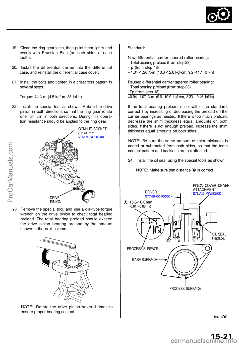
22. Instal l th e specia l too l a s shown . Rotat e th e driv e
pinio n i n bot h direction s s o tha t th e rin g gea r rotat e
on e ful l tur n i n bot h directions . Durin g thi s opera -
tio n resistanc e shoul d b e applie d to th e rin g gear .
LOCKNU T SOCKET ,36 x 41 m m07HAA-SF1010 0
DRIVEPINIO N
Remov e th e specia l tool , an d us e a dial-typ e torqu e
wrenc h o n th e driv e pinio n t o chec k tota l bearin g
preload . Th e tota l bearin g preloa d shoul d excee d
th e driv e pinio n bearin g preloa d b y th e amoun t
show n i n th e nex t column .
NOTE : Rotat e th e driv e pinio n severa l time s t o
ensur e prope r bearin g contact .
=0.94 -1.0 7 N- m (9. 6 -10. 9 kgf-cm , 8.3 3 - 9.4 6 Ibf-in )
If th e tota l bearin g preloa d i s no t withi n th e standard ,
correc t i t b y increasin g o r decreasin g th e preloa d o n th e
carrie r bearing s a s needed . I f ther e is to o muc h preload ,
decreas e th e shi m thicknes s equa l amount s o n bot h
sides . I f ther e i s no t enoug h preload , increas e th e shi m
thicknes s equa l amount s o n bot h sides .
NOTE : B e sur e th e sam e amoun t o f shi m thicknes s i s
adde d o r subtracte d fro m bot h sides , s o tha t th e toot h
contac t patter n an d backlas h ar e no t affected .
24 . Instal l th e oi l sea l usin g th e specia l tool s a s shown .
NOTE: Mak e sur e tha t distanc e i s correct .
DRIVER07749-001000 0
PINION COVE R DRIVE RATTACHMEN T07LAD-PW5050 0
15.5-16.0 m m(0.6 1 - 0.63 in)
OIL SEA L
Replace .
PROCES S SURFAC E
BAS E SURFAC E
PROCESS SURFAC E
= 1.0 4 -1.2 6 N- m (10. 6 -12. 8 kgf-cm , 9. 2 -11. 1 Ibf-in )
Reuse d differentia l carrie r tapere d rolle r bearing :
Tota l bearin g preloa d (fro m ste p 23 )
- T p (fro m ste p 18 )
Standard
:
Ne w differentia l carrie r tapere d rolle r bearing :
Tota l bearin g preloa d (fro m ste p 23 )
-Tp (fro m ste p 18 )
ProCarManuals.com
Page 945 of 1954
Driveshafts
Removal
1. Loose n th e whee l nut s slightly .
2 . Rais e th e fron t o f th e vehicle , an d suppor t i t wit h
safet y stand s in th e prope r location s (se e sectio n 1 ).
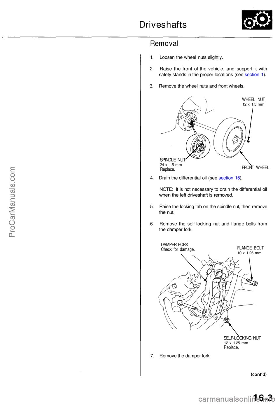
3 . Remov e th e whee l nut s an d fron t wheels .
WHEEL NU T12 x 1. 5 m m
SPINDL E NU T24 x 1. 5 m mReplace . FRON
T WHEE L
4. Drai n th e differentia l oi l (se e sectio n 15 ).
NOTE : I t i s no t necessar y t o drai n th e differentia l oi l
whe n th e lef t driveshaf t i s removed .
5. Rais e th e lockin g ta b o n th e spindl e nut , the n remov e
the nut .
6. Remov e th e self-lockin g nu t an d flang e bolt s fro m
th e dampe r fork .
DAMPE R FOR K
Chec k fo r damage . FLANG
E BOL T
10 x 1.2 5 mm
7. Remov e th e dampe r fork .
SELF-LOCKIN G NU T12 x 1.2 5 mmReplace .
ProCarManuals.com
Page 1017 of 1954
Reassembly (cont'd )
d. Determin e th e require d thicknes s o f th e 4 4 m m
shim s b y subtractin g th e clearanc e obtaine d i n th e
ste p - "C " fro m th e tota l thicknes s o f th e fou r shims .
(Tota l thicknes s o f th e fou r shims ) - (Clearance ) =
Require d thicknes s o f th e shim s
NOTE : Selec t th e shim s s o tha t th e tota l thicknes s
i s clos e to , bu t les s tha n th e require d thickness .
Example:
Measuremen t i s 0.2 8 m m (0.01 1 in) :
0.0 7 - 0.2 8 = 0.4 2 m m (0.02 8 - 0.01 1 = 0.01 7 in )
Th e selecte d shim s shoul d b e 0.2 5 m m (0.01 0 in ) an d
0.1 5 m m (0.00 6 in ) i n thickness .
I f th e require d shi m thicknes s i s 0.1 0 m m o r less , n o
shim s ar e necessary .
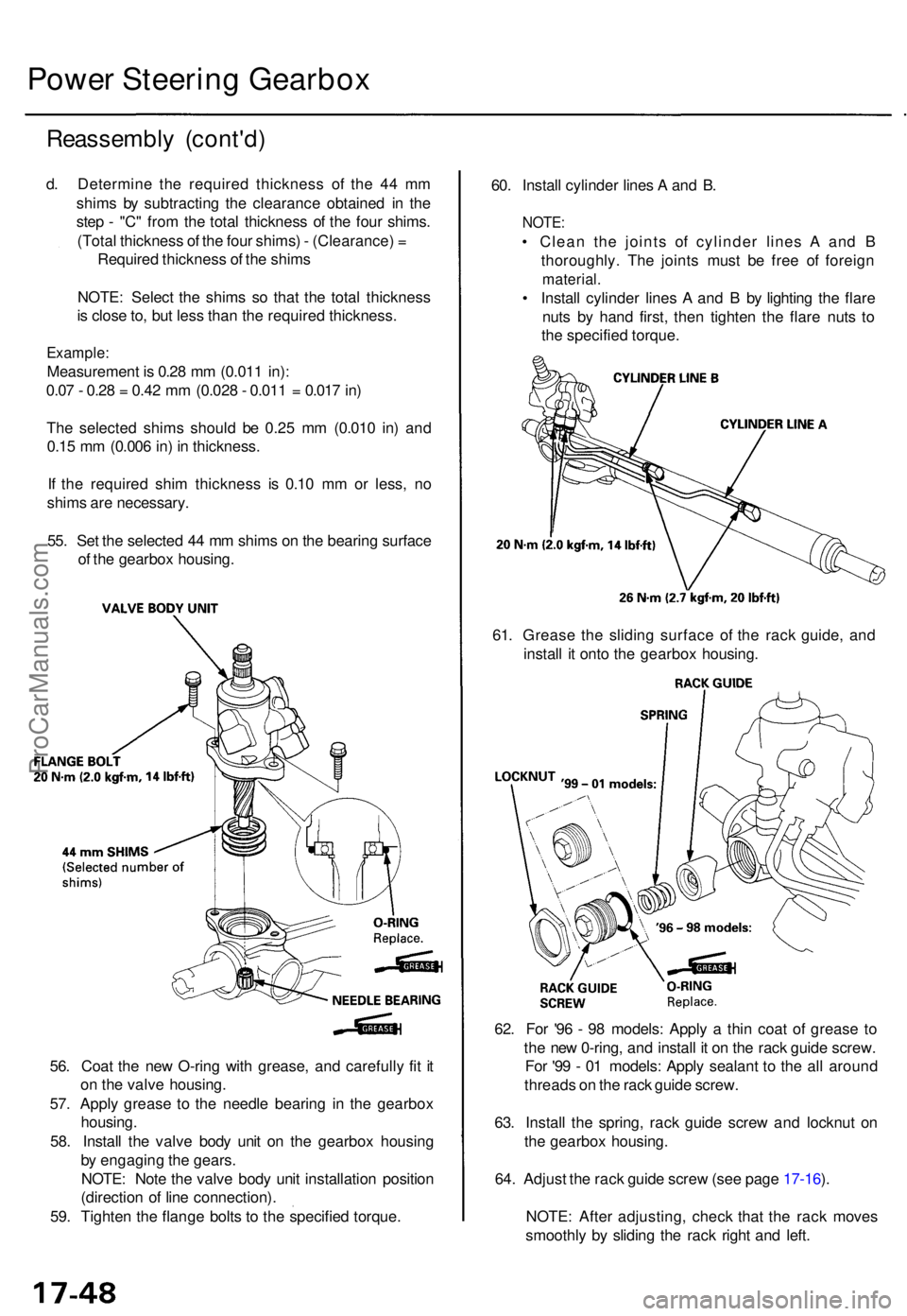
55 . Se t th e selecte d 4 4 m m shim s o n th e bearin g surfac e
o f th e gearbo x housing . 60
. Instal l cylinde r line s A an d B .
NOTE :
• Clea n th e joint s o f cylinde r line s A an d B
thoroughly . Th e joint s mus t b e fre e o f foreig n
material .
• Instal l cylinde r line s A an d B by lightin g th e flar e
nut s b y han d first , the n tighte n th e flar e nut s t o
th e specifie d torque .
Power Steerin g Gearbo x
61. Greas e th e slidin g surfac e of the rac k guide , an d
instal l i t ont o th e gearbo x housing .
62 . Fo r '9 6 - 9 8 models : Appl y a thi n coa t o f greas e t o
th e ne w 0-ring , an d instal l i t o n th e rac k guid e screw .
Fo r '9 9 - 0 1 models : Appl y sealan t t o th e al l aroun d
thread s o n th e rac k guid e screw .
63 . Instal l th e spring , rac k guid e scre w an d locknu t o n
th e gearbo x housing .
64 . Adjus t th e rac k guid e scre w (se e pag e 17-16 ).
NOTE : Afte r adjusting , chec k tha t th e rac k move s
smoothl y b y slidin g th e rac k righ t an d left .
56
. Coa t th e ne w O-rin g wit h grease , an d carefull y fi t i t
o n th e valv e housing .
57 . Appl y greas e t o th e needl e bearin g i n th e gearbo x
housing .
58 . Instal l th e valv e bod y uni t o n th e gearbo x housin g
b y engagin g th e gears.
NOTE : Not e th e valv e bod y uni t installatio n positio n
(directio n o f lin e connection) .
59 . Tighte n th e flang e bolt s t o th e specifie d torque .
ProCarManuals.com
Page 1018 of 1954
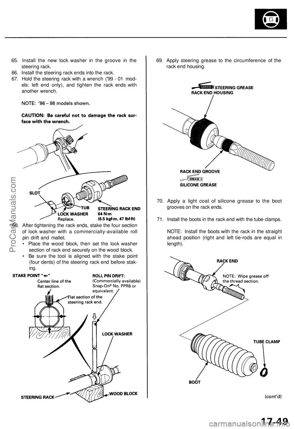
65. Install the new lock washer in the groove in the
steering rack.
66. Install the steering rack ends into the rack.
67. Hold the steering rack with a wrench ('99 - 01 mod-
els: left end only), and tighten the rack ends with
another wrench.
69. Apply steering grease to the circumference of the
rack end housing.
70. Apply a light coat of silicone grease to the boot
grooves on the rack ends.
71. Install the boots in the rack end with the tube clamps.
NOTE: Install the boots with the rack in the straight
ahead position (right and left tie-rods are equal in
length).
68. After tightening the rack ends, stake the four section
of lock washer with a commercially-available roll
pin drift and mallet.
• Place the wood block, then set the lock washer
section of rack end securely on the wood block.
• Be sure the tool is aligned with the stake point
(four dents) of the steering rack end before stak-
ing.ProCarManuals.com
Page 1019 of 1954
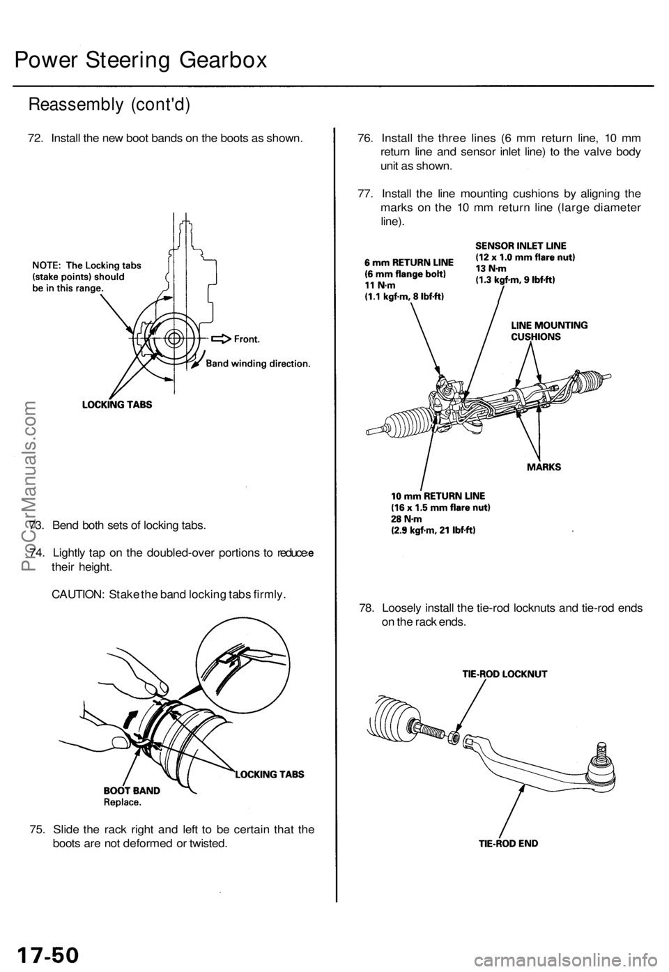
75. Slid e th e rac k righ t an d lef t t o b e certai n tha t th e
boot s ar e no t deforme d o r twisted . 78
. Loosel y instal l th e tie-ro d locknut s an d tie-ro d end s
o n th e rac k ends .
73
. Ben d bot h set s o f lockin g tabs .
74 . Lightl y ta p o n th e doubled-ove r portion s t o reduc e
thei r height .
CAUTION : Stak e th e ban d lockin g tab s firmly . 76
. Instal l th e thre e line s ( 6 m m retur n line , 1 0 m m
retur n lin e an d senso r inle t line ) t o th e valv e bod y
uni t a s shown .
77 . Instal l th e lin e mountin g cushion s b y alignin g th e
mark s o n th e 1 0 m m retur n lin e (larg e diamete r
line).
Reassembl y (cont'd )
72. Instal l th e ne w boo t band s o n th e boot s a s shown .
Power Steerin g Gearbo x
ProCarManuals.com
Page 1031 of 1954
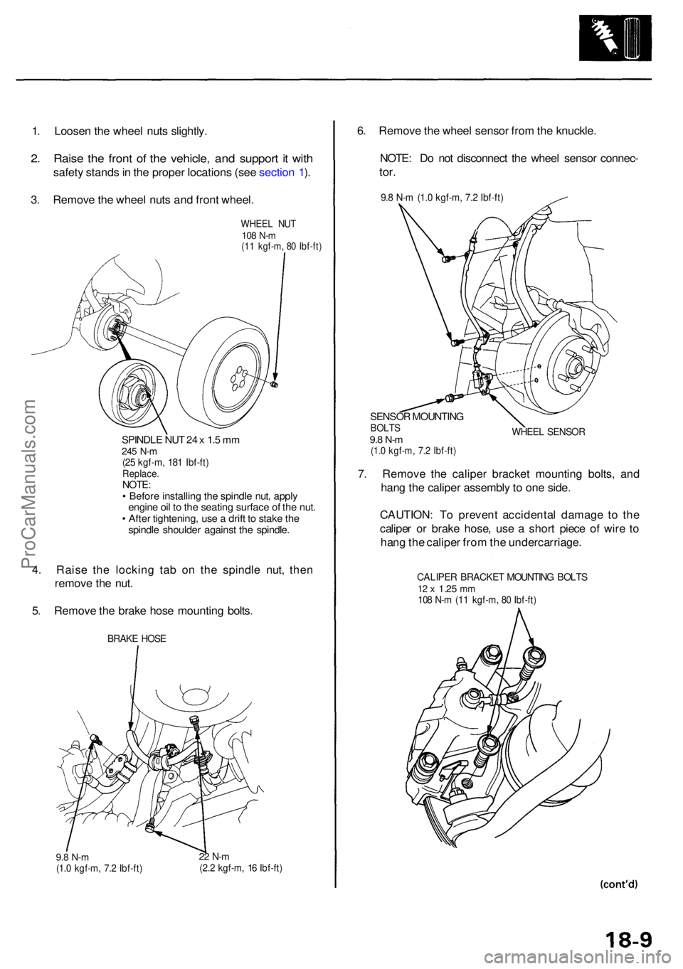
1. Loose n th e whee l nut s slightly .
2. Rais e th e fron t o f th e vehicle , an d suppor t i t wit h
safet y stand s in th e prope r location s (se e sectio n 1 ).
3 . Remov e th e whee l nut s an d fron t wheel .
WHEE L NU T108 N- m(11 kgf-m , 8 0 Ibf-ft )
SPINDL E NU T 2 4 x 1. 5 m m245 N- m(25 kgf-m , 18 1 Ibf-ft )Replace .NOTE:• Befor e installin g th e spindl e nut , appl y
engin e oi l t o th e seatin g surfac e o f th e nut .
• Afte r tightening , us e a drif t t o stak e th e
spindl e shoulde r agains t th e spindle .
4. Rais e th e lockin g ta b o n th e spindl e nut , the n
remov e th e nut .
5 . Remov e th e brak e hos e mountin g bolts .
BRAK E HOS E
9.8 N- m(1.0 kgf-m , 7. 2 Ibf-ft )22 N- m(2.2 kgf-m , 1 6 Ibf-ft )
6. Remov e th e whee l senso r fro m th e knuckle .
NOTE : D o no t disconnec t th e whee l senso r connec -
tor.
9.8 N- m (1. 0 kgf-m , 7. 2 Ibf-ft )
SENSO R MOUNTIN GBOLTS9.8 N- m(1.0 kgf-m , 7. 2 Ibf-ft )
WHEE L SENSO R
7. Remov e th e calipe r bracke t mountin g bolts , an d
han g th e calipe r assembl y t o on e side .
CAUTION : T o preven t accidenta l damag e t o th e
calipe r o r brak e hose , us e a shor t piec e o f wir e t o
han g th e calipe r fro m th e undercarriage .
CALIPER BRACKE T MOUNTIN G BOLT S12 x 1.2 5 mm108 N- m (1 1 kgf-m , 8 0 Ibf-ft )
ProCarManuals.com
Page 1045 of 1954
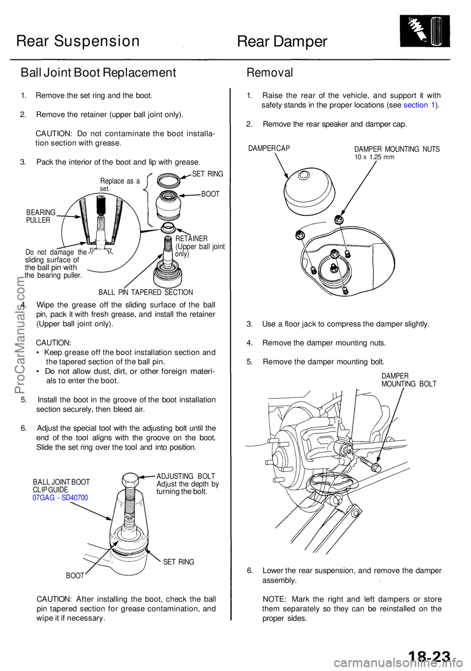
Rear Dampe r
Do no t damag e th eslidin g surfac e o fthe bal l pi n wit hthe bearin g puller .
RETAINE R(Upper bal l join tonly)
BAL L PI N TAPERE D SECTIO N
4. Wip e th e greas e of f th e slidin g surfac e o f th e bal l
pin , pac k i t wit h fres h grease , an d instal l th e retaine r
(Uppe r bal l join t only) .
CAUTION :
• Kee p greas e of f th e boo t installatio n sectio n an d
th e tapere d sectio n o f th e bal l pin .
• D o no t allo w dust , dirt , o r othe r foreig n materi -
als to ente r th e boot .
5 . Instal l th e boo t i n th e groov e o f th e boo t installatio n
sectio n securely , the n blee d air .
6 . Adjus t th e specia l too l wit h th e adjustin g bol t unti l th e
en d o f th e too l align s wit h th e groov e o n th e boot .
Slid e th e se t rin g ove r th e too l an d int o position .
BALL JOIN T BOO T
CLI P GUID E
07GA G - SD4070 0 ADJUSTIN
G BOL TAdjust th e dept h b yturnin g th e bolt .
SET RIN G
BOO T
CAUTION : Afte r installin g th e boot , chec k th e bal l
pi n tapere d sectio n fo r greas e contamination , an d
wip e it i f necessary .
Removal
1. Rais e th e rea r o f th e vehicle , an d suppor t i t wit h
safet y stand s in th e prope r location s (se e sectio n 1 ).
2 . Remov e th e rea r speake r an d dampe r cap .
DAMPE R CA P
DAMPER MOUNTIN G NUT S10 x 1.2 5 mm
3. Us e a floo r jac k t o compres s th e dampe r slightly .
4 . Remov e th e dampe r mountin g nuts .
5 . Remov e th e dampe r mountin g bolt .
DAMPE RMOUNTIN G BOL T
6. Lowe r th e rea r suspension , an d remov e th e dampe r
assembly .
NOTE : Mar k th e righ t an d lef t damper s o r stor e
the m separatel y s o the y can be reinstalle d o n th e
prope r sides .
SET RIN G
BOO T
Ball Join t Boo t Replacemen t
1. Remov e th e se t rin g an d th e boot .
2 . Remov e th e retaine r (uppe r bal l join t only) .
CAUTION : D o no t contaminat e th e boo t installa -
tio n sectio n wit h grease .
3 . Pac k th e interio r o f th e boo t an d li p wit h grease .
Replace a s aset .
BEARIN GPULLER
Rear Suspension
ProCarManuals.com
Page 1051 of 1954
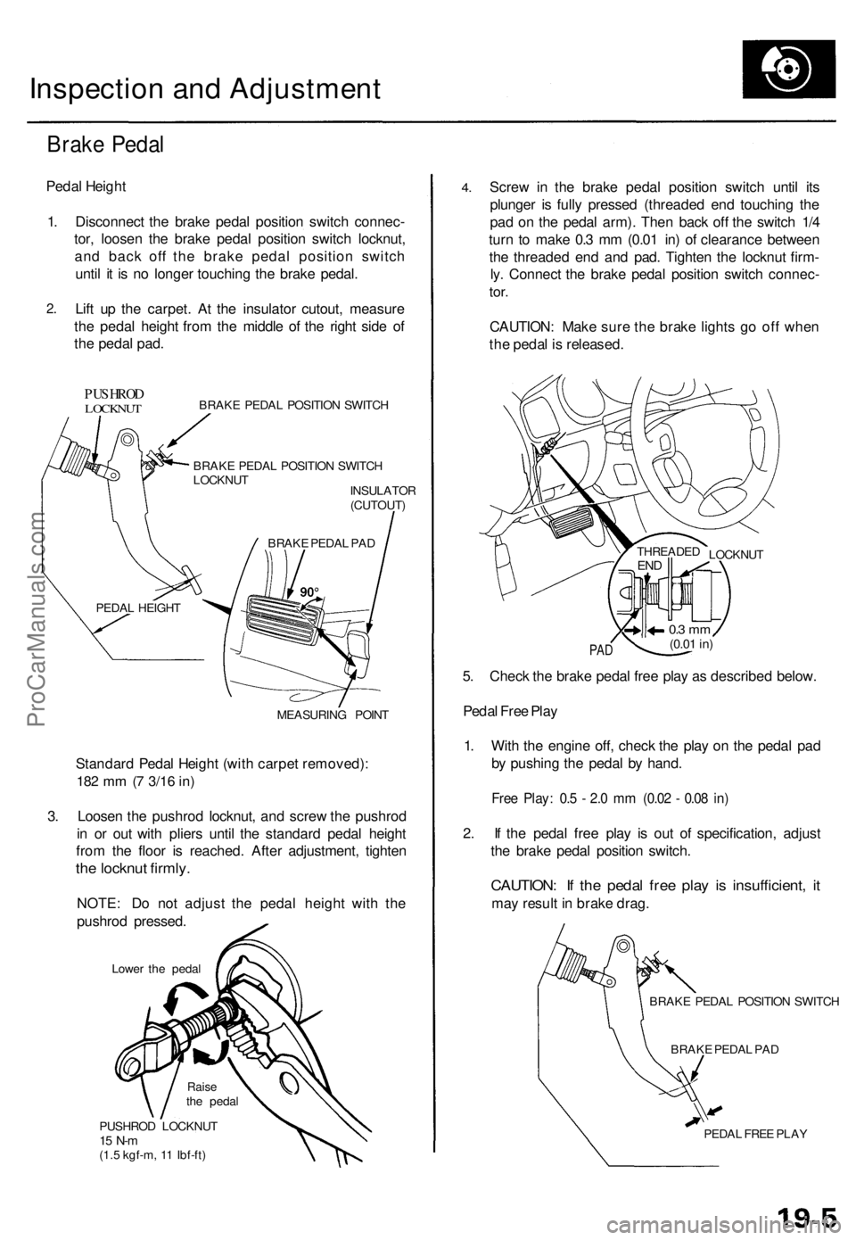
Inspection and Adjustment
Brake Pedal
Pedal Height
1. Disconnect the brake pedal position switch connec-
tor, loosen the brake pedal position switch locknut,
and back off the brake pedal position switch
until it is no longer touching the brake pedal.
2.
Lift up the carpet. At the insulator cutout, measure
the pedal height from the middle of the right side of
the pedal pad.
PUSHROD
LOCKNUT
BRAKE PEDAL POSITION SWITCH
BRAKE PEDAL POSITION SWITCH
LOCKNUT
INSULATOR
(CUTOUT)
MEASURING POINT
Standard Pedal Height (with carpet removed):
182 mm (7
3/16
in)
3. Loosen the pushrod locknut, and screw the pushrod
in or out with pliers until the standard pedal height
from the floor is reached. After adjustment, tighten
the locknut firmly.
NOTE: Do not adjust the pedal height with the
pushrod pressed.
Lower the pedal
PUSHROD LOCKNUT
15 N-m
(1.5 kgf-m, 11 Ibf-ft)
4.
Screw in the brake pedal position switch until its
plunger is fully pressed (threaded end touching the
pad on the pedal arm). Then back off the switch 1/4
turn to make 0.3 mm (0.01 in) of clearance between
the threaded end and pad. Tighten the locknut firm-
ly. Connect the brake pedal position switch connec-
tor.
CAUTION: Make sure the brake lights go off when
the pedal is released.
PAD
5. Check the brake pedal free play as described below.
Pedal Free Play
1. With the engine off, check the play on the pedal pad
by pushing the pedal by hand.
Free Play: 0.5 - 2.0 mm (0.02 - 0.08 in)
2. If the pedal free play is out of specification, adjust
the brake pedal position switch.
CAUTION: If the pedal free play is insufficient, it
may result in brake drag.
BRAKE PEDAL POSITION SWITCH
BRAKE PEDAL PAD
PEDAL FREE PLAY
LOCKNUT
THREADED
END
0.3 mm
(0.01
in)
BRAKE PEDAL PAD
PEDAL HEIGHT
Raise
the pedalProCarManuals.com