1996 ACURA RL KA9 light
[x] Cancel search: lightPage 542 of 1954
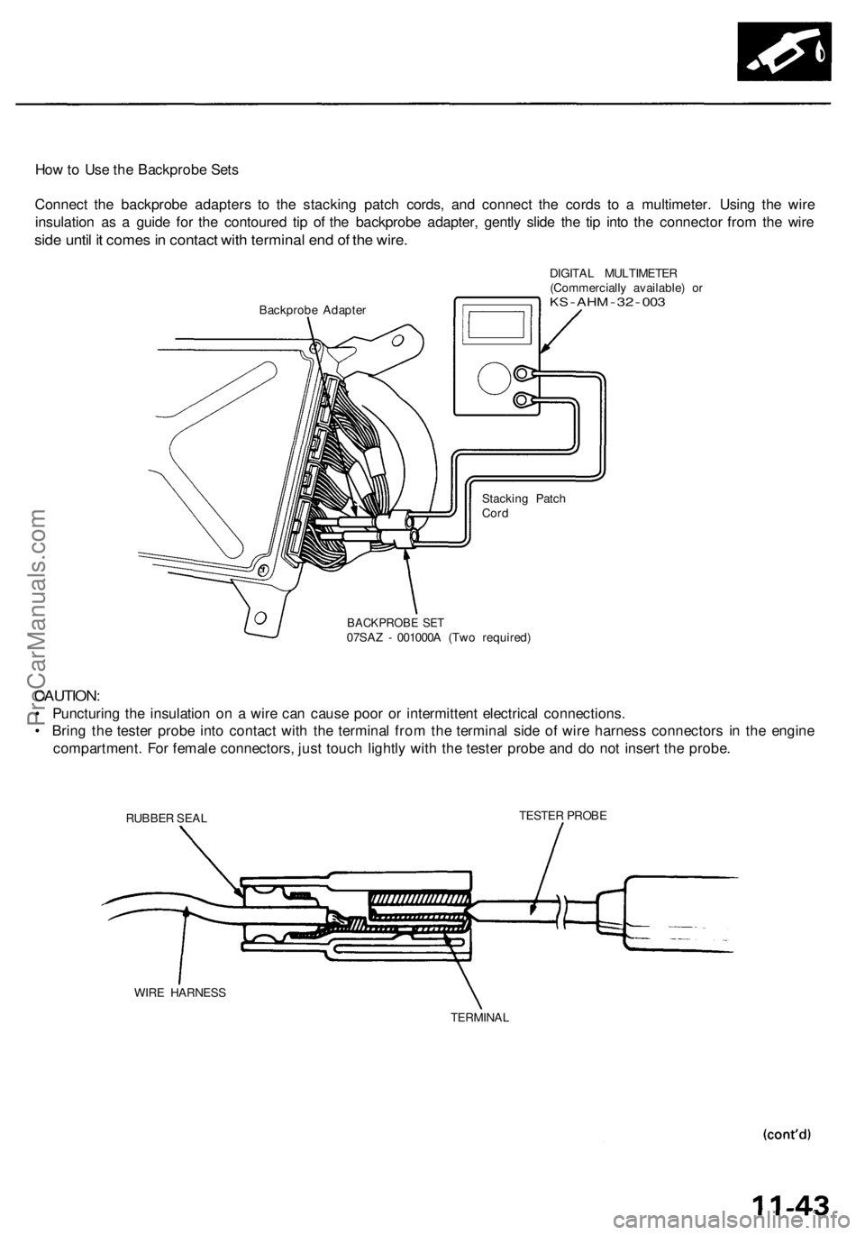
How to Use the Backprobe Sets
Connect the backprobe adapters to the stacking patch cords, and connect the cords to a multimeter. Using the wire
insulation as a guide for the contoured tip of the backprobe adapter, gently slide the tip into the connector from the wire
side until it comes in contact with terminal end of the wire.
Backprobe Adapter
DIGITAL MULTIMETER
(Commercially available) or
KS
-
AHM
-
32
-
003
Stacking Patch
Cord
BACKPROBE SET
07SAZ - 001000A (Two required)
CAUTION:
• Puncturing the insulation on a wire can cause poor or intermittent electrical connections.
• Bring the tester probe into contact with the terminal from the terminal side of wire harness connectors in the engine
compartment. For female connectors, just touch lightly with the tester probe and do not insert the probe.
TESTER PROBE
RUBBER SEAL
WIRE HARNESS
TERMINALProCarManuals.com
Page 559 of 1954

PGM-FI Syste m
System Descriptio n (cont'd )
3. Fue l Cut-of f Contro l
• Durin g deceleratio n wit h th e throttl e valv e closed , curren t t o th e injector s i s cu t of f t o improv e fue l econom y a t
speed s ove r 1,00 0 rpm .
• Fue l cut-of f actio n als o take s plac e whe n engin e spee d exceed s 5,90 0 rpm , regardles s o f th e positio n o f th e throttl e
valve, t o protec t th e engin e fro m over-revving .
4. A/ C Compresso r Clutc h Rela y
Whe n th e PC M receive s a deman d fo r coolin g fro m th e ai r conditionin g system , i t delay s th e compresso r fro m bein g
energized , an d enriche s th e mixtur e to assur e a smoot h transitio n t o th e A/ C mode .
5 . Evaporativ e Emissio n (EVAP ) Control .
Whe n th e engin e coolan t temperatur e i s abov e 99° F (37°C) : '9 6 - 9 9 models , 140° F (60°C) : '0 0 - 0 4 models , th e PC M
control s th e EVA P caniste r purg e valv e whic h control s vacuu m to th e EVA P canister .
6 . Intak e Manifol d Runne r Contro l (IMRC )
Whe n engin e spee d i s belo w 3,20 0 rpm , th e IMR C Solenoi d Valv e 1 an d IMR C Solenoi d Valv e 2 ar e activate d b y a sig -
na l fro m th e PCM . Intak e ai r flow s throug h a lon g chambe r path , increasin g torqu e a t lo w RPM .
Whe n engin e spee d is 3,20 0 - 3,80 0 rpm , th e IMR C Solenoi d Valv e is deactivate d b y th e PCM . Intak e ai r flow s throug h a
shor t chambe r path , increasin g mid-rang e torque .
Whe n th e engin e rp m is abov e 3,80 0 rpm , th e IMR C Solenoi d Valv e 1 an d IMR C Solenoi d Valv e 2 ar e deactivate d b y th e
PCM . Thi s create s a ver y shor t intak e pat h an d increase s high-spee d torque .
7 . Exhaus t Ga s Recirculatio n (EGR ) Contro l
Whe n th e EG R is require d fo r contro l o f oxide s o f nitroge n (NOx ) emissions , th e PC M control s th e EG R contro l valv e
vacuu m solenoi d valv e whic h supplie s regulate d vacuu m to th e EG R valve .
EC M Fail-safe/Back-u p Function s
1. Fail-saf e Functio n
When a n abnormalit y occur s i n a signa l fro m a sensor , th e PC M ignore s tha t signa l an d assume s a pre-programme d
valu e fo r tha t senso r tha t allow s th e engine to continu e t o run .
2 . Back-u p Functio n
Whe n a n abnormalit y occur s i n th e PC M itself , th e fue l injector s ar e controlle d b y a back-u p circui t independen t o f th e
syste m in orde r t o permi t minima l driving .
3 . Self-diagnosi s Functio n [Malfunctio n Indicato r Lam p (MIL) ]
Whe n a n abnormalit y occur s i n a signa l fro m a sensor , th e PC M supplie s groun d fo r th e MI L an d store s th e DT C in
erasabl e memory . Whe n th e ignitio n i s initiall y turne d on , th e PC M supplie s groun d fo r th e MI L fo r 2 second s t o chec k
the MI L bul b condition .
4. Tw o Tri p Detectio n Metho d ('9 6 - 9 7 models )
T o preven t fals e indications , th e Tw o Tri p Detectio n Metho d i s use d fo r th e HO2S , fue l metering-related , idl e contro l
system , EC T sensor , EG R syste m self-diagnosti c function s an d EVA P contro l system . Whe n a n abnormalit y occurs , th e
PC M store s i t i n it s memory . Whe n th e sam e abnormalit y recur s afte r th e ignitio n switc h i s turne d OF F an d O N (II )
again , th e PC M inform s th e drive r b y lightin g th e MIL .
However , t o eas e troubleshooting , thi s functio n i s cancelle d whe n yo u shor t th e servic e chec k connector . Th e MI L wil l
the n blin k immediatel y whe n a n abnormalit y occurs .
5 . Tw o Drivin g Cycl e Detectio n Metho d ('9 6 - 9 7 models )
A "Drivin g Cycle " consist s o f startin g th e engine , beginnin g close d loo p operation , an d stoppin g th e engine . I f misfir -
in g tha t increase s emissions , EVA P contro l syste m malfunctio n o r TW C deterioratio n i s detecte d durin g tw o consecu -
tiv e drivin g cycles , th e PC M turn s th e MI L on .
However , t o eas e troubleshooting , thi s functio n i s cancelle d whe n yo u shor t th e servic e chec k connector . Th e MI L wil l
the n blin k immediatel y whe n a n abnormalit y occurs .
6 . Tw o Drivin g Cycl e Detectio n Metho d ('9 8 - 0 4 models )
T o preven t fals e indications , th e "tw o drivin g cycl e detectio n method " i s use d fo r th e HO2S , fue l metering-related , idl e
contro l system , EC T sensor , EG R system , TW C an d EVA P contro l syste m an d othe r self-diagnosti c functions . Whe n a n
abnormalit y occurs , th e PC M store s it i n it s memory . Whe n th e sam e abnormalit y recur s afte r switc h is turne d OF F an d
O N (II ) again , th e PC M inform s th e drive r b y turnin g o n th e MIL .
ProCarManuals.com
Page 612 of 1954
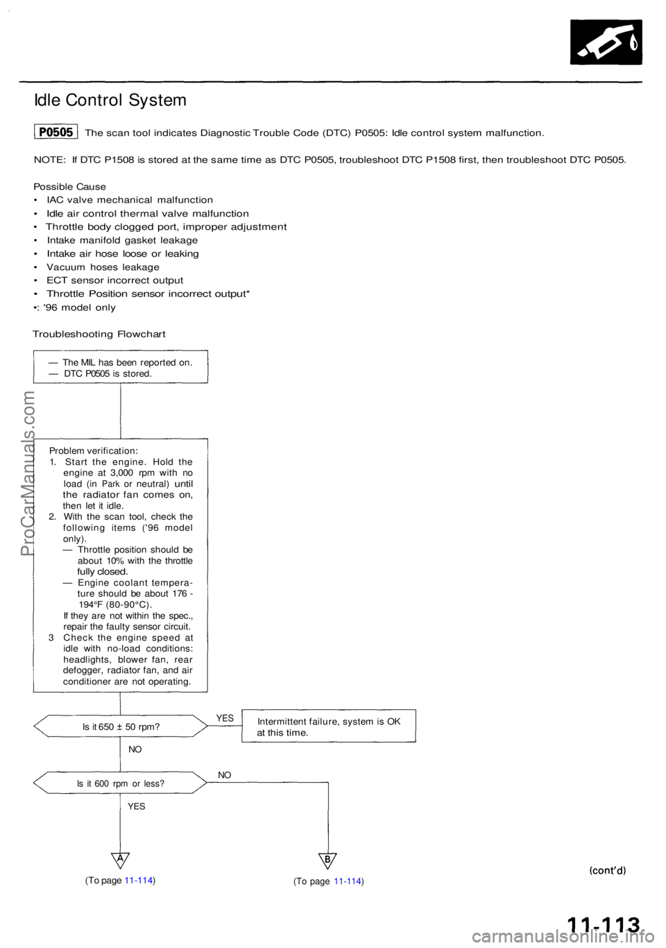
Idle Contro l Syste m
NOTE: I f DT C P150 8 is store d a t th e sam e tim e a s DT C P0505 , troubleshoo t DT C P150 8 first , the n troubleshoo t DT C P0505 .
Possibl e Caus e
• IA C valv e mechanica l malfunctio n
• Idl e ai r contro l therma l valv e malfunctio n
• Throttl e bod y clogge d port , imprope r adjustmen t
• Intak e manifol d gaske t leakag e
• Intak e ai r hos e loos e o r leakin g
• Vacuu m hose s leakag e
• EC T senso r incorrec t outpu t
• Throttl e Positio n senso r incorrec t output *
•: '9 6 mode l onl y
— Th e MI L ha s bee n reporte d on .
— DT C P050 5 is stored .
Proble m verification :
1 . Star t th e engine . Hol d th e
engin e a t 3,00 0 rp m wit h n o
loa d
(in Par k or neutral ) untilthe radiato r fa n come s on ,then le t i t idle .
2 . Wit h th e sca n tool , chec k th e
followin g item s ('9 6 mode l
only) .
— Throttl e positio n shoul d b e
abou t 10 % wit h th e throttl e
fully closed .— Engin e coolan t tempera -
tur e shoul d b e abou t 17 6 -
194° F (80-90°C) .
I f the y ar e no t withi n th e spec. ,
repai r th e fault y senso r circuit .
3 Chec k th e engin e spee d a t
idl e wit h no-loa d conditions :
headlights , blowe r fan , rea r
defogger , radiato r fan , an d ai r
conditione r ar e no t operating .
Is i t 65 0 5 0 rpm ?
NO
Is i t 60 0 rp m o r less ?
YES
Intermitten t failure , syste m is O Kat thi s time .
NO
(T o pag e 11-114 ) (T o pag e 11-114 )
YES
The sca n too l indicate s Diagnosti c Troubl e Cod e (DTC ) P0505 : Idl e contro l syste m malfunction .
Troubleshootin g Flowchar t
ProCarManuals.com
Page 617 of 1954
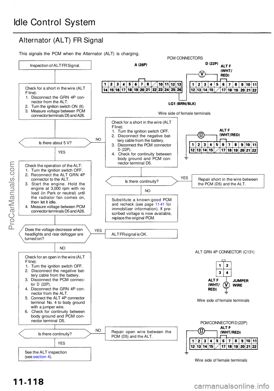
Idle Contro l Syste m
Alternato r (ALT ) F R Signa l
PCM CONNECTOR S
Is ther e abou t 5 V ?
YE S
Chec k th e operatio n o f th e ALT :
1 . Tur n th e ignitio n switc h OFF .
2 . Reconnec t th e AL T GR N 4 P
connecto r t o th e ALT .
3 . Star t th e engine . Hol d th e
engin e a t 3,00 0 rp m wit h n o
loa d (i n Par k o r neutral ) unti l
th e radiato r fa n come s on ,
then le t i t idle .4. Measur e voltag e betwee n PC M
connecto r terminal s D 5 an d A26 .
Doe s th e voltag e decreas e whe n
headlight s an d rea r defogge r ar e
turne d on ?
NO
Chec k fo r a n ope n in th e wir e (AL T
F line) :
1 . Tur n th e ignitio n switc h OFF .
2 . Disconnec t th e negativ e bat -
ter y cabl e fro m th e battery .
3 . Disconnec t th e PC M connec -
tor D (22P) .4. Disconnec t th e GR N 4 P con -
necto r fro m th e ALT .
5 . Connec t th e AL T 4 P connecto r
termina l No . 4 to bod y groun d
wit h a jumpe r wire .
6 . Chec k fo r continuit y betwee n
body groun d an d PC M con -necto r termina l D5 .
I s ther e continuity ?
YES
See th e AL T inspectio n
(see sectio n 4 ).
N O
Wir e sid e o f femal e terminal s
Chec k fo r a shor t i n th e wir e (AL T
F line) :
1 . Tur n th e ignitio n switc h OFF .
2 . Disconnec t th e negativ e bat -
ter y cabl e fro m th e battery .
3 . Disconnec t th e PC M connecto r
D (22P) .4. Chec k fo r continuit y betwee n
bod y groun d an d PC M con -
necto r termina l D5 .
I s ther e continuity ? Repai
r shor t i n th e wir e betwee n
the PC M (D5 ) and th e ALT .
NO
Substitut e a known-goo d PC Mand rechec k (se e pag e 11-4 1 fo rimmobilize r information) . I f pre -
scribe d voltag e is no w available ,
replac e th e origina l PCM .
AL T F R signa l i s OK .
ALT GR N 4 P CONNECTO R (C131 )
Repair ope n wir e betwee n th ePCM (D5 ) and th e ALT .
PCM CONNECTO R D (22P )
Wir e sid e o f femal e terminal s
NO
Wir e sid e o f femal e terminal s
YES YE
S
This signal s th e PC M whe n th e Alternato r (ALT ) i s charging .
Inspection o f AL T F R Signal .
Chec k fo r a shor t i n th e wir e (AL T
F line) :
1 . Disconnec t th e GR N 4 P con -
necto r fro m th e ALT .
2 . Tur n th e ignitio n switc h O N (II) .
3 . Measur e voltag e betwee n PC M
connecto r terminal s D 5 an d A26 .
ProCarManuals.com
Page 621 of 1954

Idle Contro l Syste m
Brake Peda l Positio n Switc h Signa l
Are th e brak e light s o n withou t
depressin g th e brak e pedal ? Inspec
t th e brak e peda l positio n
switc h (se e sectio n 19 ).
N O
Depres s th e brak e pedal .
D o th e brak e light s com e on ?
YES
Is th e fus e OK ?NO
Chec k fo r a n ope n i n th e wir e
(BKS W line) :
1 . Depres s th e brak e pedal .
2 . Measur e voltag e betwee n PC M
connecto r terminal s E 2 an d
A2 6 wit h th e brak e peda l de -
pressed . —
Repai r shor t i n th e wire be-
twee n th e brak e peda l posi -
tio n switc h an d th e STO P
HOR N (1 5 A ) fuse .
— Replac e th e STO P HOR N (1 5 A )
fuse .
Wire sid e o f femal e terminal s
I s ther e batter y voltage ? Repai
r ope n in th e wir e betwee n
th e PC M (E2 ) an d th e brak e peda l
positio n switch .
Brak e peda l positio n switc h sig -
nal i s OK .
YES
NO
— Repai r ope n i n th e wir e be -
twee n th e brak e peda l posi -
tio n switc h an d th e STO P
HOR N (1 5 A ) fuse .
— Inspec t th e brak e peda l posi -
tio n switc h (se e sectio n 19 ).
PC M CONNECTOR S
YES
NOInspec t th e STO P HOR N (1 5 A )
fus e i n th e under-hoo d fuse / rela y
box.
YES
Inspectio n o f Brak e Peda l Positio n
Switc h Signal .
This signal s th e PC M whe n th e brak e peda l i s depressed .
ProCarManuals.com
Page 623 of 1954

Idle Contro l Syste m
Idle Spee d Settin g
Inspection/Adjustmen t
NOTE:
• Befor e settin g th e idl e speed , chec k th e followin g
items:
— Th e MI L ha s no t bee n reporte d on .
— Ignitio n timin g
— Spar k plug s
— Ai r cleane r
— PC V syste m
• (Canada ) Depres s th e parkin g brak e pedal . Star t th e
engine , the n chec k tha t th e headlight s ar e off .
1 . Connec t a OBDI I sca n too l (se e pag e 11-40 ) o r
tachometer .
• Connec t a tachomete r t o ignite r uni t secondar y
loo p (white-taped) .
• Remov e th e rubbe r ca p fro m th e tachomete r
connecto r an d connec t a tachometer .
TACHOMETE RCONNECTORTACHOMETE R
RUBBERCAP
BATTER Y
2. Star t th e engine . Hol d th e engin e a t 3,00 0 rp m wit h
n o loa d (i n Par k o r neutral ) unti l th e radiato r fa n
come s on , the n le t i t idle . 3
. Disconnec t th e IA C valv e connector .
IAC VALV E
4. I f th e engin e stalls , star t th e engin e wit h th e acceler -
ato r peda l slightl y depressed . Stabiliz e th e rp m a t
1,000 , the n slowl y releas e th e peda l unti l th e engin e
idles .
5 . Chec k idlin g unde r th e followin g conditions : head -
light s (Hi ) an d rea r defogge r on , blowe r fan , radia -
to r fan , an d ai r conditione r ar e no t operating .
Idl e spee d shoul d be :
480 5 0 rp m
(in Par k o r neutral )
Adjust th e idl e speed , i f necessary , b y turnin g th e
idl e adjustin g screw .
NOTE : Afte r adjustin g th e idl e spee d i n thi s step ,
rechec k th e ignitio n timin g (se e sectio n 4 ).
I f i t i s ou t o f spec , g o bac k t o ste p 4 .
IDL E ADJUSTIN G SCRE W
TACHOMETE
R
ProCarManuals.com
Page 624 of 1954
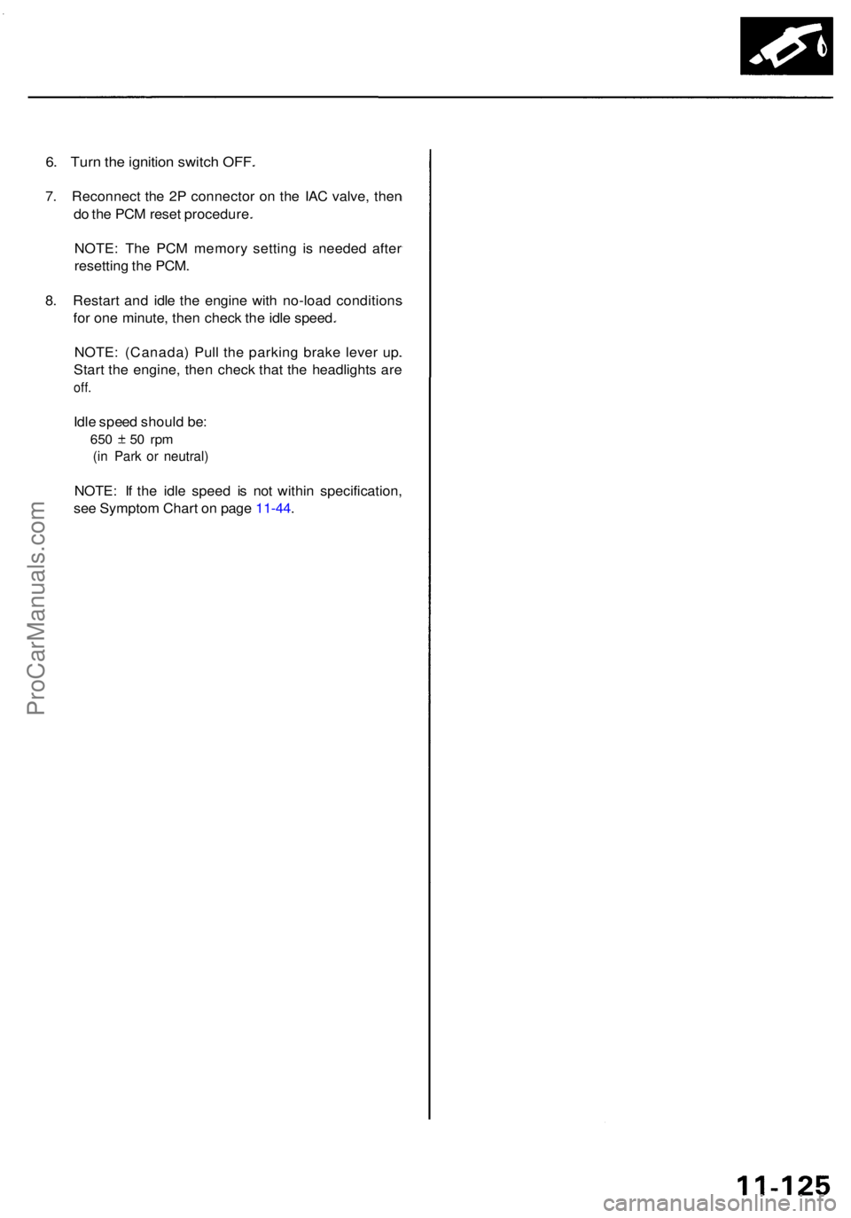
6. Tur n th e ignitio n switc h OFF .
7. Reconnec t th e 2 P connecto r o n th e IA C valve , the n
d o th e PC M rese t procedure .
NOTE : Th e PC M memor y settin g i s neede d afte r
resettin g th e PCM .
8 . Restar t an d idl e th e engin e wit h no-loa d condition s
fo r on e minute , the n chec k th e idl e speed .
NOTE : (Canada ) Pul l th e parkin g brak e leve r up .
Star t th e engine , the n chec k tha t th e headlight s ar e
off.
Idle spee d shoul d be :
650 5 0 rp m
(in Par k o r neutral )
NOTE: I f th e idl e spee d i s no t withi n specification ,
se e Sympto m Char t o n pag e 11-44 .
ProCarManuals.com
Page 625 of 1954
PCM Memory Setting
NOTE: The PCM reset procedure and disconnecting the
battery or the BACK UP RADIO (7.5 A) fuse cancels the
PCM memory for idle control. The following procedure
is needed after the PCM reset procedure and reconnect-
ing the battery or the BACK UP RADIO (7.5 A) fuse.
1. Start the engine. Hold the engine at 3,000 rpm with
no load (in Park or neutral) until the radiator fan
comes on.
2. Let the engine idle for approx. 5 minutes under the
following conditions:
• Transmission in Park or neutral
• A/C switch OFF
• Headlights OFF
• Rear defogger OFFProCarManuals.com