Page 57 of 1954
Cellular Phon e Antenn a Replacemen t
1. Remov e th e rea r ceilin g light .
2 . Disconnec t th e connecto r fro m th e antenna .
3 . Remov e th e nu t fro m th e antenna .
CELLULA R PHON E ANTENN A
CONNECTOR
NUT5 N- m(0.5 kgf-m , 4 Ibf-ft )
ProCarManuals.com
Page 166 of 1954

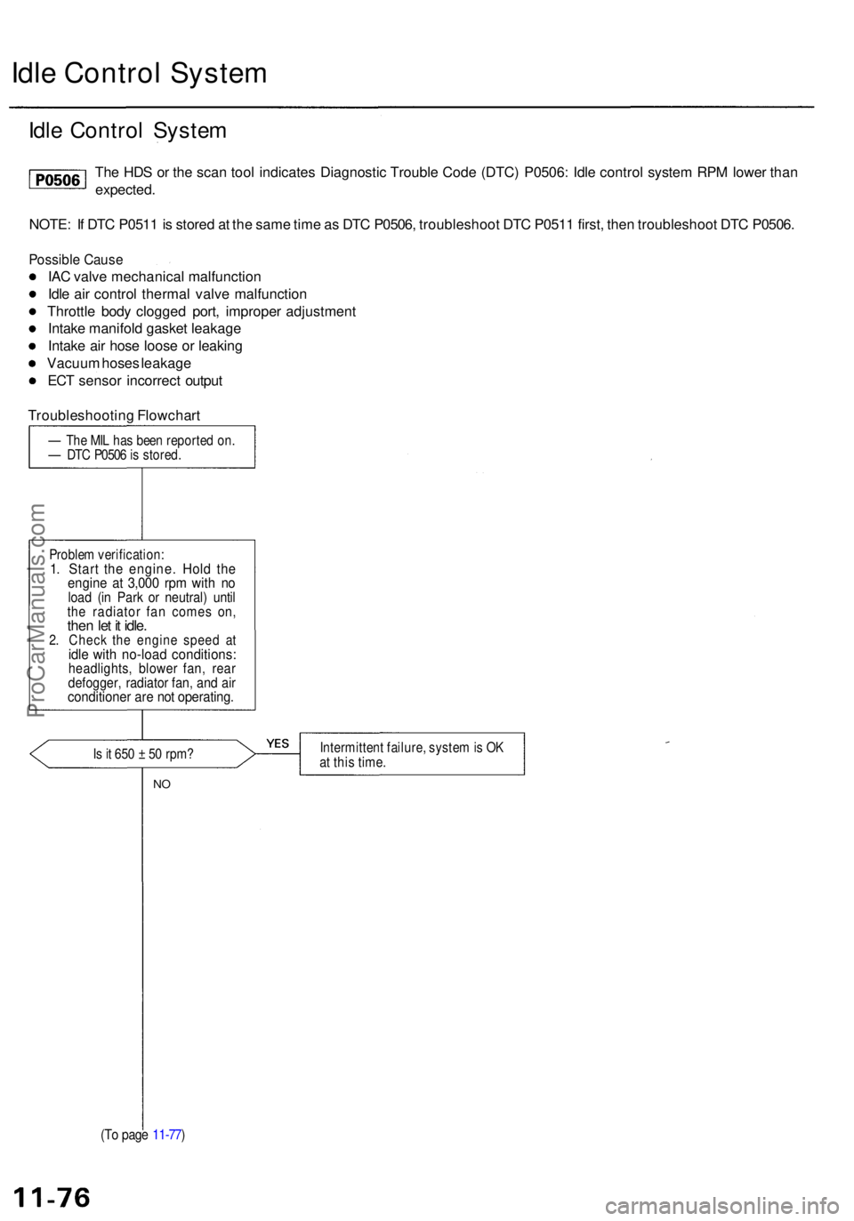
Idle Contro l Syste m
Idle Contro l Syste m
The HD S o r th e sca n too l indicate s Diagnosti c Troubl e Cod e (DTC ) P0506 : Idl e contro l syste m RP M lowe r tha n
expected .
NOTE : I f DT C P051 1 is store d a t th e sam e tim e a s DT C P0506 , troubleshoo t DT C P051 1 first , the n troubleshoo t DT C P0506 .
Possibl e Caus e
IAC valv e mechanica l malfunctio n
Idl e ai r contro l therma l valv e malfunction
Throttl e bod y clogge d port , imprope r adjustmen t
Intak e manifol d gaske t leakag e
Intak e ai r hos e loos e o r leakin g
Vacuu m hose s leakag e
EC T senso r incorrec t outpu t
Troubleshootin g Flowchar t
— Th e MI L ha s bee n reporte d on .— DT C P050 6 is stored .
Proble m verification :
1. Star t th e engine . Hol d th eengin e a t 3,00 0 rp m wit h n oloa d (i n Par k o r neutral ) unti lthe radiato r fa n come s on ,then le t i t idle .2. Chec k th e engin e spee d a tidle wit h no-loa d conditions :headlights, blowe r fan , rea rdefogger , radiato r fan , an d ai rconditione r ar e no t operating .
Is it 65 0 ± 50 rpm ?Intermitten t failure , syste m is O Kat thi s time .
NO
(T o pag e 11-77 )
ProCarManuals.com
Page 168 of 1954

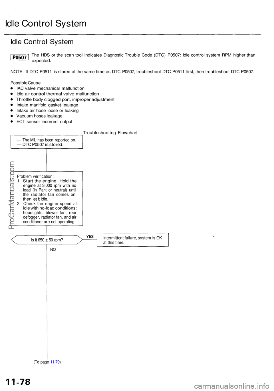
Idle Contro l Syste m
Idle Contro l Syste m
The HD S o r th e sca n too l indicate s Diagnosti c Troubl e Cod e (DTC ) P0507 : Idl e contro l syste m RP M highe r tha n
expected .
NOTE: I f DT C P051 1 i s store d a t th e sam e tim e a s DT C P0507 , troubleshoo t DT C P051 1 first , the n troubleshoo t DT C P0507 .
Possibl e Caus e
IA C valv e mechanica l malfunctio n
Idle ai r contro l therma l valv e malfunctio n
Throttle bod y clogge d port , imprope r adjustmen t
Intake manifol d gaske t leakag e
Intak e ai r hos e loos e o r leakin g
Vacuu m hose s leakag e
EC T senso r incorrec t outpu t
Troubleshootin g Flowchar t
— Th e MI L ha s bee n reporte d on .— DT C P050 7 is stored .
Problem verification :1. Star t th e engine . Hol d th eengin e a t 3,00 0 rp m wit h n oloa d (i n Par k o r neutral ) unti lthe radiato r fa n come s on ,then le t i t idle .2 Chec k th e engin e spee d a tidle wit h no-loa d conditions :headlights , blowe r fan , rea rdefogger , radiato r fan , an d ai rconditione r ar e no t operating .
Is it 65 0 ± 5 0 rpm ?Intermitten t failure , syste m is O Kat thi s time .
NO
(T o pag e 11-79 )
ProCarManuals.com
Page 171 of 1954
Brake Peda l Positio n Switc h Signa l
This signal s th e PC M whe n th e brak e peda l i s depressed .
Are th e brak e light s o n withou t
depressin g th e brak e pedal ? Inspec
t th e brak e peda l positio n
switc h (se e sectio n 19) .
NO
Depres s th e brak e pedal .
D o th e brak e light s com e on ?
YES
Is th e fus e OK ?
Chec k fo r a n ope n i n th e wir e
(BKS W line) :
1 . Depres s th e brak e pedal .
2 . Measur e voltag e betwee n PC M
connecto r terminal s E 2 an d
A2 6 wit h th e brak e peda l de -
pressed . —
Repai r shor t i n th e wir e be -
twee n th e brak e peda l posi -
tio n switc h an d th e STO P
HOR N (2 0 A ) fuse .
— Replac e th e STO P HOR N (2 0 A )
fuse .
Is ther e batter y voltage ? Repai
r ope n in th e wir e betwee n
th e PC M (E2 ) an d th e brak e peda l
positio n switch .
Brak e peda l positio n switc h sig -
nal i s OK .
ProCarManuals.com
Page 192 of 1954

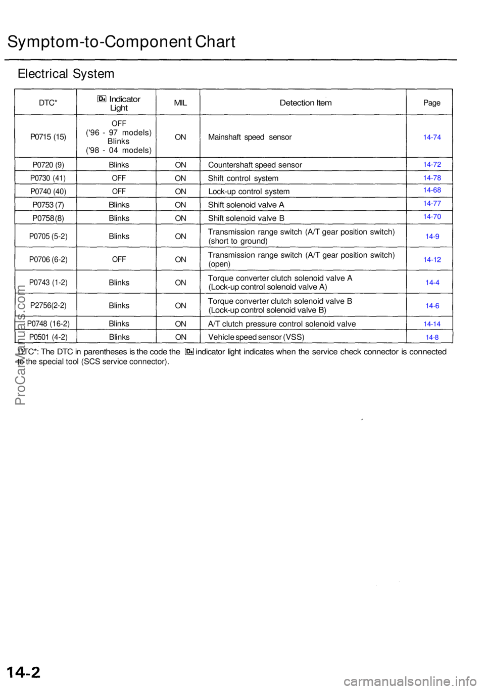
Symptom-to-Component Char t
Electrica l Syste m
DTC*
P071 5 (15 )
P072 0 (9 )
P073 0 (41 )
P074 0 (40 )
P075 3 (7 )
P075 8 (8 )
P070 5 (5-2 )
P070 6 (6-2 )
P074 3 (1-2 )
P2756(2-2 )
P0748 (16-2 )
P0501 (4-2 )
Indicato rLight
OFF
('96 - 9 7 models )
Blink s
('9 8 - 0 4 models )
Blink s
OFF
OFF
Blink s
Blink s
Blink s
OFF
Blink s
Blink s
Blink s
Blink s
MIL
ON
O N
O N
O N
ON
O N
O N
O N
O N
ON
O N
O N
Detectio n Ite m
Mainshaf t spee d senso r
Countershaf t spee d senso r
Shif t contro l syste m
Lock-u p contro l syste m
Shift solenoi d valv e A
Shif t solenoi d valv e B
Transmissio n rang e switc h (A/ T gea r positio n switch )
(shor t t o ground )
Transmissio n rang e switc h (A/ T gea r positio n switch )
(open)
Torqu e converte r clutc h solenoi d valv e A(Lock-u p contro l solenoi d valv e A )
Torqu e converte r clutc h solenoi d valv e B
(Lock-u p contro l solenoi d valv e B )
A/ T clutc h pressur e contro l solenoi d valv e
Vehicl e spee d senso r (VSS )
Page
14-9
14-1 2
14-4
14-6
14-1 4
14- 8
DTC* : Th e DT C in parenthese s is th e cod e th e indicato r ligh t indicate s whe n th e servic e chec k connecto r i s connecte d
to th e specia l too l (SC S servic e connector) .
14-74
14-72
14-78
14-77
14-70 14-68
ProCarManuals.com
Page 193 of 1954
If th e self-diagnosti c indicator light doe s no t blink , perfor m a n inspectio n accordin g t o th e tabl e below .
Sympto m
indicato r ligh t doe s no t com e o n fo r tw o second s afte r ignitio n
switc h is firs t turne d o n (II) .
indicato r ligh t i s o n constantl y (no t blinking ) wheneve r th e ignitio n
switc h is o n (II) .
Shif t leve r canno t b e move d fro m positio n wit h th e brak e peda l
pressed .
Ignitio n ke y canno t b e move d fro m AC C (1 ) positio n to LOC K (0 ) positio n
while pushin g th e ignitio n ke y wit h th e shif t leve r i s in position . Inspectio
n
Chec k interloc k syste m
-shif t loc k syste m
Chec k interloc k syste m
-ke y interloc k syste m Ref
. pag e
14-79
14-81
14-82
14-84
ProCarManuals.com
Page 204 of 1954

Electrical Troubleshooting
Troubleshooting Flowchart — A/T Clutch Pressure Control Solenoid Valve
• OBD II Scan Tool indicates Code
P0748.
• Self-diagnosis indicator light
indicates Code 16.
Measure A/T clutch pressure con-
trol solenoid valve Resistance at
Solenoid Connector:
1. Disconnect the shift solenoid
valve/A/T clutch pressure con-
trol solenoid valve harness 4P
connector.
2. Measure the resistance of the
A/T clutch pressure control
solenoid valve.
Is the resistance approx. 5 ?
YES
Check A/T Clutch Pressure
Control Solenoid Valve for a
Short Circuit:
1. Disconnect the E (26P) con-
nector from the PCM.
2. Check for continuity between
body ground and the E16 termi-
nal and E3 terminal individually.
Is there continuity?
NO
Measure A/T Clutch Pressure
Control Solenoid Valve Resistance:
1. Connect the shift solenoid
valve/A/T clutch pressure con-
trol solenoid valve harness 4P
connector.
2. Measure the resistance
between the E16 and E3 ter-
minals.
Is the resistance approx. 5 ?
YES
Check the VB SOL Voltage:
1. Disconnect the A (26P) and E
(26P) connectors from the
PCM.
2. Turn the ignition switch ON (II).
3. Measure the voltage between
the E1 and A26 terminals.
Is there voltage?
YES
Check for loose PCM connectors.
If necessary, substitute a known-
good PCM and recheck.
Possible Cause
• Disconnected A/T clutch pres-
sure control solenoid valve con-
nector
• Short or open in A/T clutch
pressure control solenoid valve
wire
• Faulty A/T clutch pressure con-
trol solenoid valve
• Open VB SOL line
Replace the A/T clutch pressure
control solenoid valve.
Repair short in the wires
between the E16 and E3 termi-
nals and the A/T clutch pressure
control solenoid valve.
Repair loose terminal or open in
the wires between the E16 and E3
terminals and the A/T clutch pres-
sure control solenoid valve.
Check for open in the wire
between the E1 terminal and the
under-hood fuse/relay box.ProCarManuals.com
Page 205 of 1954

Headliner
Removal
CAUTION : Whe n pryin g wit h a flat-ti p screwdriver ,
wra p it wit h protectiv e tap e t o preven t damage .
NOTE:
• Tak e car e no t t o ben d an d scratc h th e headliner .
• B e carefu l no t t o damag e th e dashboar d an d othe r
interio r trim .
1. Remov e th e gra b handles .
ACCESSCOVER
2.
3.
ACCES SCOVER
Remov e thes e items . Refe r t o th e '96 - 0 1 Acur a 3. 5
R L Servic e Manual , P/ N
61SZ30 5 (see sectio n 20 ):
Rea r sea t cushio n an d rea r seat-bac k
Front an d rea r sid e tri m
Fron t an d rea r doo r tri m
Cente r pilla r tri m
Fron t pilla r tri m
Rea r pilla r tri m
Roo f sid e tri m
Windo w antenn a termina l cove r
Remov e thes e items . Refe r t o th e
'9 6 - 0 1 Acur a 3. 5
R L Servic e Manual , P/ N
61SZ30 5 (see sectio n 23 ):
• Ceilin g light s
• Moonroo f switc h 4
. Remov e th e sunviso r an d holde r fro m eac h side .
Disconnec t bot h positiv e terminals .
5.Detac h th e clip s an d hooks , the n remov e th e homelin k
an d telematic s switch . Disconnec t th e homelin k
swit h connector , telematic s switc h connector , an d
navigation , mic connector .
NAVIGATIO N MI C
CONNECTO R HOMELIN
K
SWITC H
CONNECTO R
TELEMATIC S
SWITC H
CONNECTO R
HOMELIN K an d
TELEMATIC S SWITC H
HOOKS
ProCarManuals.com