Page 360 of 1954
Cruise Control
Actuator Solenoid Test
1. Disconnect the 4P connector from the actuator.
Terminal side of
male terminals
2. Check for resistance between the terminals accord-
ing to the table.
NOTE: Resistance
will
vary
slightly
with
tempera-
ture; specified resistance is at 70°F (20°C).
VENT VALVE
From VENT
HOSE
To VACUUM
TANK
VACUUM VALVE
SAFETY VALVEProCarManuals.com
Page 413 of 1954
Valves, Valv e Spring s an d Valv e Seal s
Remova l
NOTE: Identif y valve s an d valv e spring s a s the y ar e
remove d s o tha t eac h ite m ca n b e reinstalle d i n it s origi -
nal position .
1. Usin g a n appropriate-size d socke t an d plasti c mal -
let , lightl y ta p th e valv e retaine r t o loose n th e valv e
keeper s befor e installin g th e valv e sprin g compres -
sor.
PLASTI C MALLE T
SOCKET
2. Instal l th e valv e sprin g compressor . Compres s th e
spring , an d remov e th e valv e keepers .
VALVE SPRIN GCOMPRESSO RATTACHMENT
0775 7-PJ1010 A
VALVEKEEPER S
VALVE SPRIN G COMPRESSO R
Snap-o n CF71 1 o r EQUIVALEN T
(Commerciall y available )
3. Instal l th e valv e guid e sea l remover .
VALVE SEA L
SEALREMOVE R
VALVE GUID E SEA L REMOVE R
LISL E P/ N 5790 0 o r KD335 0
o r EQUIVALEN T
(Commerciall y available )
4. Remov e th e valv e seal .
ProCarManuals.com
Page 421 of 1954

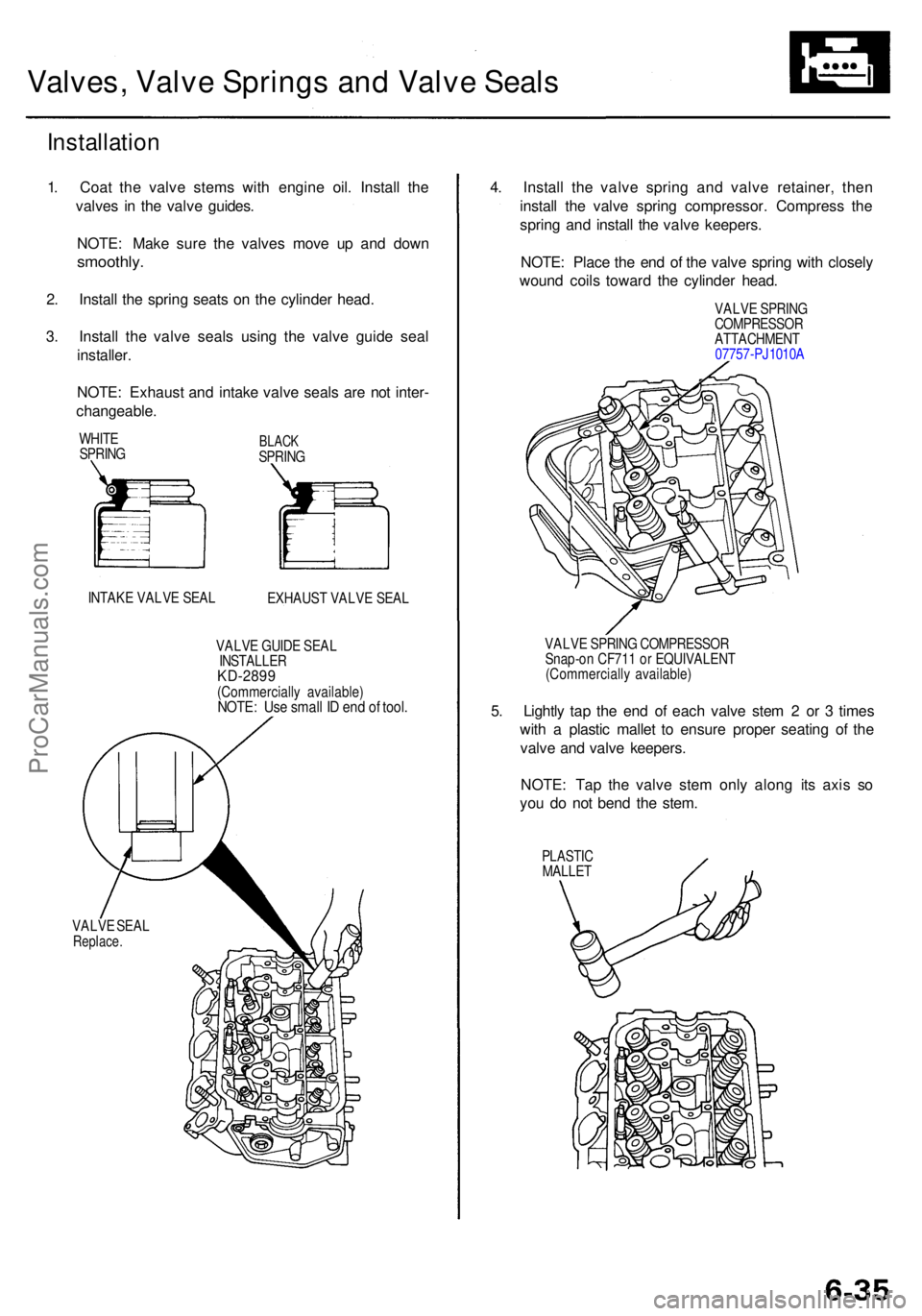
Valves, Valv e Spring s an d Valve Seals
Installatio n
1. Coa t th e valv e stem s wit h engin e oil . Instal l th e
valve s i n th e valv e guides .
NOTE : Mak e sur e th e valve s mov e u p an d dow n
smoothly .
2. Instal l th e sprin g seat s o n th e cylinde r head .
3 . Instal l th e valv e seal s usin g th e valv e guid e sea l
installer .
NOTE : Exhaus t an d intak e valv e seal s ar e no t inter -
changeable .
WHITE
SPRIN GBLACKSPRIN G
INTAK E VALV E SEA L
EXHAUST VALV E SEA L
VALV E GUID E SEA L
INSTALLE RKD-2899(Commerciall y available )NOTE: Us e smal l I D en d o f tool .
VALV E SEA LReplace .
4. Instal l th e valv e sprin g an d valv e retainer , the n
instal l th e valv e sprin g compressor . Compres s th e
sprin g an d instal l th e valv e keepers .
NOTE : Plac e th e en d o f th e valv e sprin g wit h closel y
woun d coil s towar d th e cylinde r head .
VALV E SPRIN GCOMPRESSO RATTACHMENT
0775 7-PJ1010 A
VALV E SPRIN G COMPRESSO R
Snap-o n CF71 1 o r EQUIVALEN T
(Commerciall y available )
5. Lightl y ta p th e en d o f eac h valv e ste m 2 or 3 time s
wit h a plasti c malle t t o ensur e prope r seatin g o f th e
valv e an d valv e keepers .
NOTE : Ta p th e valv e ste m onl y alon g it s axi s s o
yo u d o no t ben d th e stem .
PLASTI CMALLET
ProCarManuals.com
Page 423 of 1954
Camshafts/Rocker Arms and
Camshaft Seals
CAUTION:
• Make sure that all rockers are in alignment with their
valves when torquing the rocker assembly bolts.
• To prevent the rocker arm assembly from coming
apart, leave the camshaft holder bolts in the holes.
• Handle the rocker arms carefully so that the oil does
not come out of the hydraulic tappets.
1. Install the camshaft and rubber cap, then install the
camshaft seal with the open side (spring) facing in.
NOTE:
• Position the camshaft with pin hole at the top.
• Do not apply oil to the camshaft holder mating
surface of the camshaft seal.
• Apply liquid gasket. Part No. 08718 - 0001 or
08718 - 0003 around the rubber cap.
RUBBER CAP
Replace if there was
oil leakage.
OIL SEAL
Replace.
Seal housing surface should be dry.
Apply a light coat of oil to camshaft
and inner lip of seal.
CAMSHAFTProCarManuals.com
Page 427 of 1954

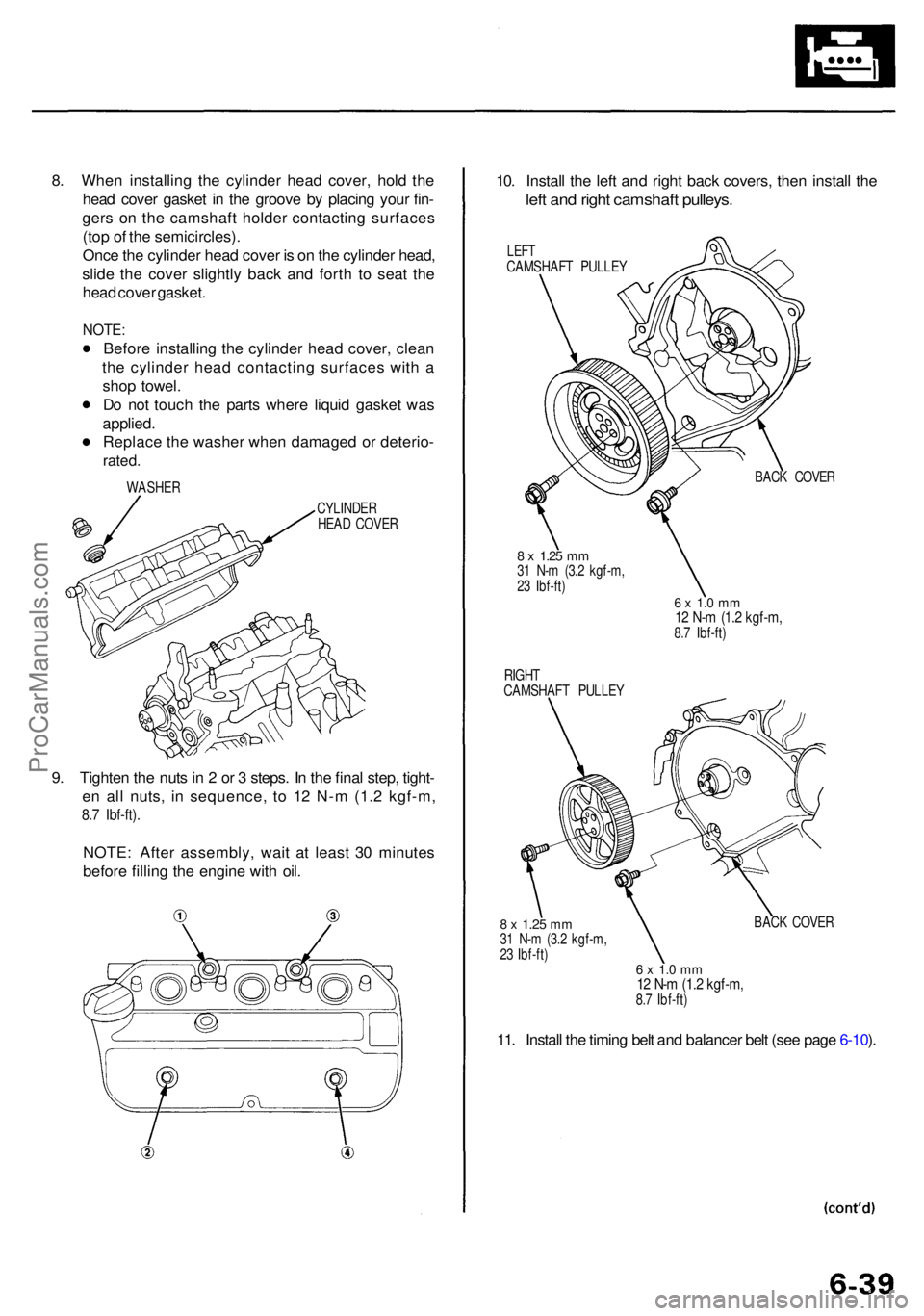
8. Whe n installin g th e cylinde r hea d cover , hol d th e
hea d cove r gaske t i n th e groov e b y placin g you r fin -
ger s o n th e camshaf t holde r contactin g surface s
(to p o f th e semicircles) .
Onc e th e cylinde r hea d cove r i s o n th e cylinde r head ,
slid e th e cove r slightl y bac k an d fort h t o sea t th e
hea d cove r gasket .
NOTE:
Before installin g th e cylinde r hea d cover , clea n
th e cylinde r hea d contactin g surface s wit h a
sho p towel .
D o no t touc h th e part s wher e liqui d gaske t wa s
applied .
Replac e th e washe r whe n damage d o r deterio -
rated.
WASHE R
CYLINDER
HEA D COVE R
9. Tighte n th e nut s in 2 or 3 steps . I n th e fina l step , tight -
e n al l nuts , i n sequence , t o 1 2 N- m (1. 2 kgf-m ,
8.7 Ibf-ft) .
NOTE : Afte r assembly , wai t a t leas t 3 0 minute s
befor e fillin g th e engin e wit h oil . 10
. Instal l th e lef t an d righ t bac k covers , the n instal l th e
left an d righ t camshaf t pulleys .
LEFTCAMSHAF T PULLE Y
BACK COVE R
8 x 1.2 5 mm31 N- m (3. 2 kgf-m ,
2 3 Ibf-ft )
RIGH T
CAMSHAF T PULLE Y
6 x 1. 0 m m12 N- m (1. 2 kgf-m ,8.7 Ibf-ft )
8 x 1.2 5 mm31 N- m (3. 2 kgf-m ,
2 3 Ibf-ft ) BAC
K COVE R
11. Instal l th e timin g bel t an d balance r bel t (se e pag e 6-10 ).
6 x 1. 0 m m12 N- m (1. 2 kgf-m ,8.7 Ibf-ft )
ProCarManuals.com
Page 457 of 1954

Crankshaft
Installation (cont'd)
10. Apply liquid gasket to the cylinder block mating sur-
face of the rear cover, then install the cover on the
cylinder block.
REAR COVER
Apply liquid gasket
along the broken line.
Do not apply liquid gasket
to O-ring groove.
NOTE:
• Use liquid gasket, Part No. 08718 - 0001 or 08718
- 0003.
• Check that the mating surfaces are clean and dry
before applying liquid gasket.
• Apply liquid gasket evenly, being careful to cover
all the mating surface.
• To prevent oil leakage, apply liquid gasket to the
inner threads of the bolt holes.
• Do not apply liquid gasket to O-ring grooves.
• Do not install the parts if five minutes or more
have elapsed since applying liquid gasket.
Instead reapply liquid gasket after removing old
residue.
• After assembly, wait at least 30 minutes before
filling the engine with oil.
Apply liquid gasket
along the broken line.
O-RING GROOVE
NOTE:
• Apply a light coat of oil to the crankshaft and to the
lip of the oil seal.
• Use a new O-ring and apply oil when installing it.
REAR COVER
DOWEL PINS
6 x 1.0 mm
12 N-m (1.2 kgf-m,
8.7 Ibf-ft)
O-RING
Replace.
11. Apply liquid gasket to the cylinder block mating sur-
face of the oil pump.
NOTE: Do not apply liquid gasket to the O-ring
grooves.
OIL PUMP
HOUSINGProCarManuals.com
Page 467 of 1954
Oil Filter
Replacement
CAUTION: Loosen the engine oil filter carefully while
the engine is hot, the hot oil may cause scalding.
1. Remove the oil filter with the special oil filter
wrench.
2. Inspect the threads and rubber seal on the new fil-
ter. Wipe off the seat on the engine block, then
apply a light coat of oil to the filter rubber seal.
NOTE: Use only filters with a built-in bypass sys-
tem.
Inspect threads and
rubber seal surface.
Apply oil to rubber seal
before installing.
(cont'd)ProCarManuals.com
Page 484 of 1954
TWC
Inspectio n
Using a flashlight , mak e a visua l chec k fo r plugging ,
meltin g o r crackin g o f th e catalyst .
TWC
FLASHLIGH T
ProCarManuals.com