1996 ACURA RL KA9 light
[x] Cancel search: lightPage 765 of 1954
Electrical Troubleshootin g
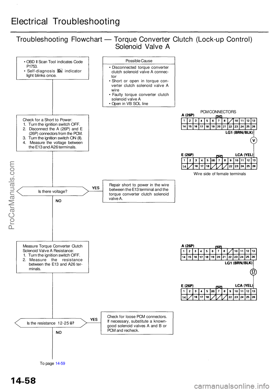
Troubleshooting Flowchar t — Torqu e Converte r Clutc h (Lock-u p Control )
Solenoi d Valv e A
• OB D II Sca n Too l indicate s Cod eP1753 .• Self-diagnosi s indicato rlight blink s once .
Chec k fo r a Shor t t o Power :1. Tur n th e ignitio n switc h OFF .2. Disconnec t th e A (26P ) an d E
(26P ) connector s fro m th e PCM .
3. Tur n th e ignitio n switc h O N (II) .4. Measur e th e voltag e betwee nthe E1 3 an d A2 6 terminals .
Is ther e voltage ?
Measur e Torqu e Converte r Clutc h
Solenoi d Valv e A Resistance :
1. Tur n th e ignitio n switc h OFF .2. Measur e th e resistanc e
betwee n th e E1 3 an d A2 6 ter -
minals .
Is th e resistanc e 12-2 5
T o pag e 14-5 9 Possibl
e Caus e
• Disconnecte d torqu e converte r
clutc h solenoi d valv e A connec -
tor• Shor t o r ope n i n torqu e con -
verte r clutc h solenoi d valv e A
wir e
• Fault y torqu e converte r clutc h
solenoi d valv e A
• Ope n in V B SO L lin e
Repai r shor t t o powe r i n th e wir e
betwee n th e E1 3 termina l an d th etorqu e converte r clutc h solenoi d
valv e A .
Chec k fo r loos e PC M connectors .
I f necessary , substitut e a known -
goo d solenoi d valve s A an d B or
PC M an d recheck . PC
M CONNECTOR S
Wir e sid e o f femal e terminal s
ProCarManuals.com
Page 786 of 1954

Troubleshooting Flowchar t — Indicato r Ligh t Doe s No t Com e O n
Is th e specia l too l (SC S Servic e
Connector ) connecte d t o th e
servic e chec k connector ?
Check th e Indicato r Light :Shift t o position .
Does th e indicato r ligh t
com e on ?
Chec k th e Groun d Circuit :
1. Tur n th e ignitio n switc h OFF .2. Disconnec t th e A (26P ) an d B(16P ) connector s fro m th ePCM .3. Chec k fo r continuit y betwee nthe A2 6 termina l an d bod ygroun d an d th e B 9 termina land bod y ground .
Is ther e continuity ?
Measur e Powe r Suppl y Circui t
Voltage :
1 . Tur n th e ignitio n switc h O N (II) .
2 . Measur e th e voltag e betwee n
terminal s A1 3 an d A2 6 an d
betwee n terminal s B 1 an d B9 .
I s ther e batter y voltage ?
T o pag e 14-8 0 Disconnec
t th e specia l too l fro m
th e servic e chec k connecto r an d
recheck .
Check fo r loos e PC M connectors .
I f necessary , substitut e a known -
goo d PC M an d recheck .
PCM CONNECTOR S
Wir e sid e o f femal e terminal s
Repai r ope n i n th e wire s betwee n
th e A2 6 o r B 9 terminal s an d G101 .
Repai r ope n o r shor t i n th e wir e
betwee n th e A1 3 and/o r B 1 termi -
nals , th e PGM-F I mai n relay , an d
th e fus e box .
The indicato r ligh t doe s no t
com e o n whe n th e ignitio n switc h
i s firs t turne d O N (II) . (I t shoul d
com e o n fo r abou t 2 seconds. )
Chec k th e Servic e Chec k Con -
nector :
Mak e sur e th e specia l too l (SC S
Servic e Connector ) i s no t con -
necte d t o th e servic e chec k con -
nector .
ProCarManuals.com
Page 789 of 1954
Electrical Troubleshootin g
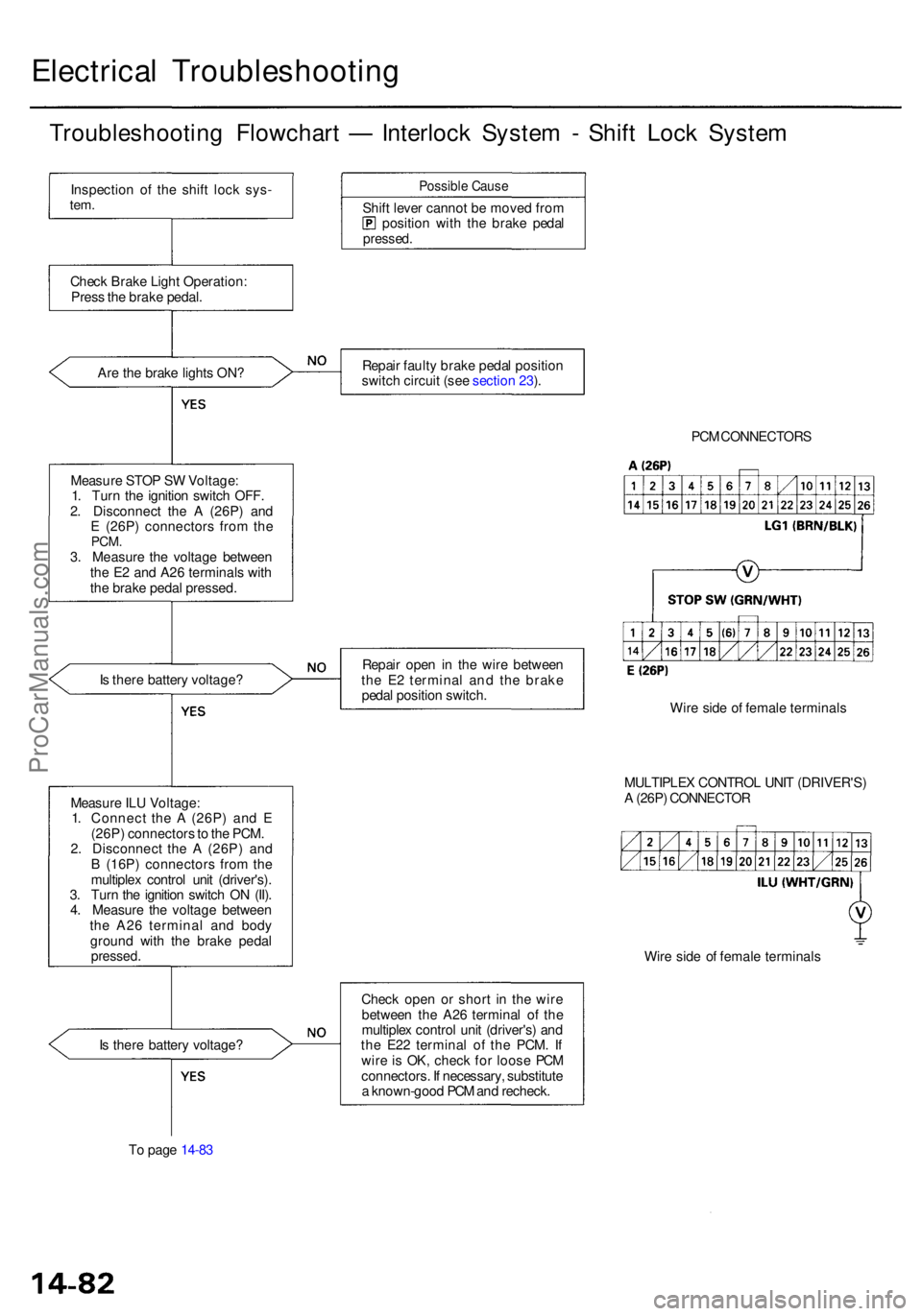
Troubleshooting Flowchar t — Interloc k Syste m - Shif t Loc k Syste m
Inspectio n o f th e shif t loc k sys -tem.
Chec k Brak e Ligh t Operation :
Pres s th e brak e pedal .
Ar e th e brak e light s ON ?
Measur e STO P S W Voltage :
1 . Tur n th e ignitio n switc h OFF .
2 . Disconnec t th e A (26P ) an d
E (26P ) connector s fro m th e
PCM .3. Measur e th e voltag e betwee n
th e E 2 an d A2 6 terminal s wit h
th e brak e peda l pressed .
I s ther e batter y voltage ?
I s ther e batter y voltage ?
T o pag e 14-8 3
Possibl e Caus e
Shift leve r canno t b e move d fro mpositio n wit h th e brak e peda lpressed .
Repair fault y brak e peda l positio n
switc h circui t (se e sectio n 23 ).
Repai r ope n i n th e wir e betwee n
th e E 2 termina l an d the brak e
peda l positio n switch .
Chec k ope n o r shor t i n th e wir e
betwee n th e A2 6 termina l o f th e
multiple x contro l uni t (driver's ) an d
th e E2 2 termina l o f th e PCM . I f
wir e i s OK , chec k fo r loos e PC M
connectors . I f necessary , substitut e
a known-goo d PC M an d recheck . PC
M CONNECTOR S
Wir e sid e o f femal e terminal s
MULTIPLE X CONTRO L UNI T (DRIVER'S )
A (26P ) CONNECTO R
Wir e sid e o f femal e terminal s
Measur
e IL U Voltage :
1 . Connec t th e A (26P ) an d E
(26P ) connector s to th e PCM .
2 . Disconnec t th e A (26P ) an d
B (16P ) connector s fro m th e
multiple x contro l uni t (driver's) .
3 . Tur n th e ignitio n switc h O N (II) .
4 . Measur e th e voltag e betwee n
th e A2 6 termina l an d bod y
groun d wit h th e brak e peda l
pressed .
ProCarManuals.com
Page 802 of 1954

18. Install the control lever.
CAUTION: Take care not to bend the shift cable.
SPRING
WASHER
CONTROL SHAFT
19. Connect the shift solenoid valve/A/T clutch pressure
control solenoid valve harness connector.
20. Install the shift solenoid valve/A/T clutch pressure
control solenoid valve harness clamp to the shift
cable cover, then install the shift cable cover onto
the transmission.
CLAMP
SHIFT CABLE
COVER
SHIFT SOLENOID VALVE/
A/T CLUTCH PRESSURE
CONTROL SOLENOID VALVE
HARNESS CONNECTOR
21. Connect the transmission range switch harness
connector, then clamp the harness clamp on the
brackets.
22. Turn the ignition switch ON (II). Move the shift lever
through all gears, and check the transmission range
switch synchronization with the A/T gear position
indicator.
GAUGE ASSEMBLY
A/T GEAR POSITION
INDICATOR
23. If the transmission range switch is not synchronized
with the A/T gear position indicator, loosen the bolts
securing the transmission range switch and adjust
the transmission range switch installation.
24. Start the engine. Move the shift lever through all
gears, and verify the following:
• The shift lever cannot be moved to the position
from the position without pushing the shift
lever.
• The engine will not start in any drive gear, only in
the or position.
• The back-up lights come on when the shift lever is
in the position.
8 x
1.25
mm
16 N-m (1.6 kgf-m, 12 Ibf-ft)
CONTROL
LEVER
6 x 1.0 mm
12 N-m (1.2 kgf-m,
8.7 Ibf-ft)ProCarManuals.com
Page 843 of 1954
Valve Bod y
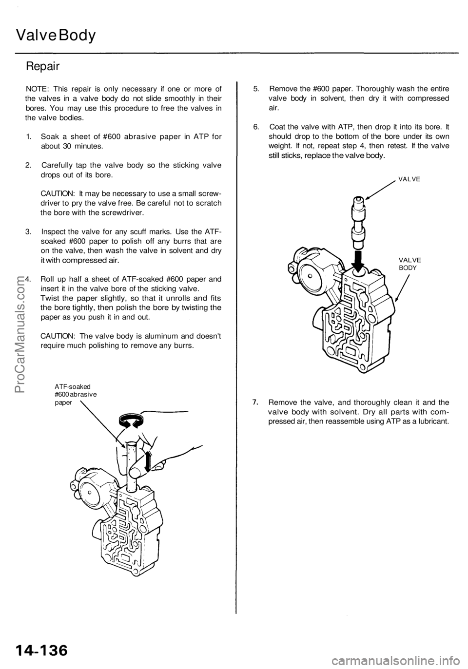
Repai r
NOTE : Thi s repai r i s onl y necessar y i f on e o r mor e o f
th e valve s i n a valv e bod y d o no t slid e smoothl y i n thei r
bores . Yo u ma y us e thi s procedur e t o fre e th e valve s i n
th e valv e bodies .
1 . Soa k a shee t o f #60 0 abrasiv e pape r i n AT P fo r
abou t 3 0 minutes .
2 . Carefull y ta p th e valv e bod y s o th e stickin g valv e
drop s ou t o f it s bore .
CAUTION : I t ma y b e necessar y to us e a smal l screw -
drive r t o pr y th e valv e free . B e carefu l no t t o scratc h
th e bor e wit h th e screwdriver .
3 . Inspec t th e valv e fo r an y scuf f marks . Us e th e ATF -
soake d #60 0 pape r t o polis h of f an y burr s tha t ar e
o n th e valve , the n was h th e valv e in solven t an d dr y
it wit h compresse d air .
4. Rol l u p hal f a shee t o f ATF-soake d #60 0 pape r an d
inser t i t i n th e valv e bor e o f th e stickin g valve .
Twist th e pape r slightly , s o tha t i t unroll s an d fit s
the bor e tightly , the n polis h th e bor e b y twistin g th e
pape r a s yo u pus h i t i n an d out .
CAUTION : Th e valv e bod y is aluminu m an d doesn' t
requir e muc h polishin g to remov e an y burrs .
ATF-soake d#600 abrasiv epaper
5. Remov e th e #60 0 paper . Thoroughl y was h th e entir e
valv e bod y i n solvent , the n dr y i t wit h compresse d
air.
6. Coa t th e valv e wit h ATP , the n dro p it int o it s bore . I t
shoul d dro p t o th e botto m o f th e bor e unde r it s ow n
weight . I f not , repea t ste p 4 , the n retest . I f th e valv e
still sticks , replac e th e valv e body .
VALV E
VALVEBODY
Remov e th e valve , an d thoroughl y clea n i t an d th e
valv e bod y wit h solvent . Dr y al l part s wit h com -
presse d air , the n reassembl e usin g AT P a s a lubricant .
ProCarManuals.com
Page 894 of 1954
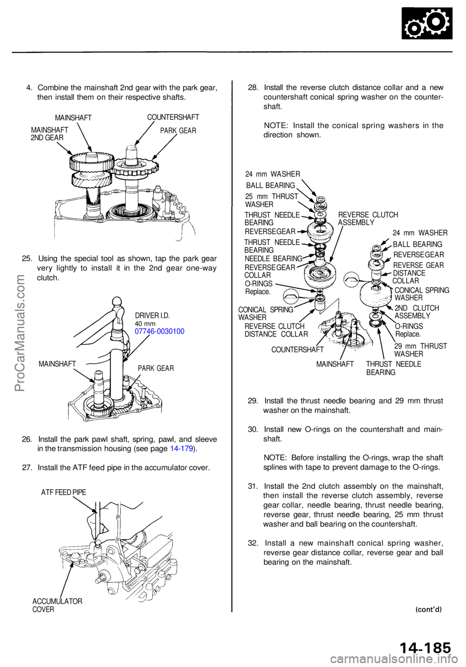
4. Combin e th e mainshaf t 2n d gea r wit h th e par k gear ,
the n instal l the m o n thei r respectiv e shafts .
MAINSHAF T
MAINSHAF T
2N D GEA R COUNTERSHAF
T
PARK GEA R
25. Usin g th e specia l too l a s shown , ta p th e par k gea r
ver y lightl y t o instal l i t i n th e 2n d gea r one-wa y
clutch .
DRIVE R I.D .40 m m07746-003010 0
MAINSHAFTPARK GEA R
26. Instal l th e par k paw l shaft , spring , pawl , an d sleev e
i n th e transmissio n housin g (se e pag e 14-179 ).
27 . Instal l th e AT F fee d pip e in th e accumulato r cover .
ATF FEE D PIP E
ACCUMULATO R
COVER
28. Instal l th e revers e clutc h distanc e colla r an d a ne w
countershaf t conica l sprin g washe r o n th e counter -
shaft.
NOTE : Instal l th e conica l sprin g washer s i n th e
directio n shown .
24 m m WASHE R
BAL L BEARIN G
2 5 m m THRUS T
WASHE R
THRUS T NEEDL E
BEARIN G
REVERS E GEA R
THRUS T NEEDL E
BEARIN G
NEEDL E BEARIN G
REVERS E GEA R
COLLA RO-RING S
Replace . REVERS
E CLUTC H
ASSEMBL Y
24 m m WASHE R
BAL L BEARIN G
REVERS E GEA R
REVERS E GEA RDISTANC ECOLLAR
CONICA L SPRIN GWASHE R
2ND CLUTC H
ASSEMBL Y
O-RING S
Replace .
2 9 m m THRUS T
WASHE R
MAINSHAF T THRUS T NEEDL E
BEARIN G
CONICA
L SPRIN G
WASHE R
REVERS E CLUTC H
DISTANC E COLLA R
COUNTERSHAF T
29. Instal l th e thrus t needl e bearin g an d 2 9 m m thrus t
washe r o n th e mainshaft .
30 . Instal l ne w O-ring s o n th e countershaf t an d main -
shaft.
NOTE : Befor e installin g th e O-rings , wra p th e shaf t
spline s wit h tap e to preven t damag e to th e O-rings .
31 . Instal l th e 2n d clutc h assembl y o n th e mainshaft ,
the n instal l th e revers e clutc h assembly , revers e
gea r collar , needl e bearing , thrus t needl e bearing ,
revers e gear , thrus t needl e bearing , 2 5 m m thrus t
washe r an d bal l bearin g o n th e countershaft .
32 . Instal l a ne w mainshaf t conica l sprin g washer ,
revers e gea r distanc e collar , revers e gea r an d bal l
bearin g o n th e mainshaft .
ProCarManuals.com
Page 922 of 1954

Use a dial-typ e torqu e wrenc h o n th e driv e pinio n to
measur e th e driv e pinio n bearin g preloa d (Tp) .
Standard : 1.4 2 - 1.9 1 N- m
(14. 5 - 19. 5 kgf-cm , 12. 6 - 16. 9 Ibf-in )
7. Reinstal l th e differentia l carrie r an d th e differentia l
cas e cover , the n measur e th e tota l bearin g preload .
Th e tota l bearin g preloa d shoul d excee d th e driv e
pinio n bearin g preloa d (Tp ) by :
Standard :
0.94 - 1.0 7 N- m (9. 6 - 10. 9 kgf-cm , 8.3 3 - 9.4 6 Ibf-in )
Example :
Total bearin g preloa d (fro m ste p 7 )
- T p (fro m ste p 6 ) Gea
r toot h contac t
8 . Remov e th e differentia l cas e cove r an d differentia l
carrier . Clea n an d pain t th e rin g gea r teet h lightl y an d
evenl y wit h Prussia n Blu e (o n bot h side s of eac h
tooth) .
9 . Reinstal l th e differentia l carrie r an d th e differentia l
cas e cover , the n torqu e th e bolt s in a crisscros s pat -
ter n in severa l steps .
10 . Instal l th e specia l too l a s shown , the n rotat e th e
driv e pinio n i n bot h direction s s o tha t th e rin g gea r
rotat e on e ful l tur n i n bot h directions . Durin g thi s
operatio n resistanc e shoul d b e applie d t o th e rin g
gear .
LOCKNU T SOCKET ,36 x 41 m m07HAA-SF1010 0
DRIVEPINIO N
11. Remov e th e differentia l cas e cove r an d th e differen -
tia l carrier , the n chec k th e toot h contac t pattern .
CORREC T TOOT H CONTAC T
TOE CONTAC T HEE L CONTAC T
FLANK CONTAC T FAC E CONTAC T
15-11
= 0.9 4 - 1.0 7 N- m (9. 6 - 10. 9 kgf-cm , 8.3 3 - 9.4 6 Ibf-in )
ProCarManuals.com
Page 931 of 1954
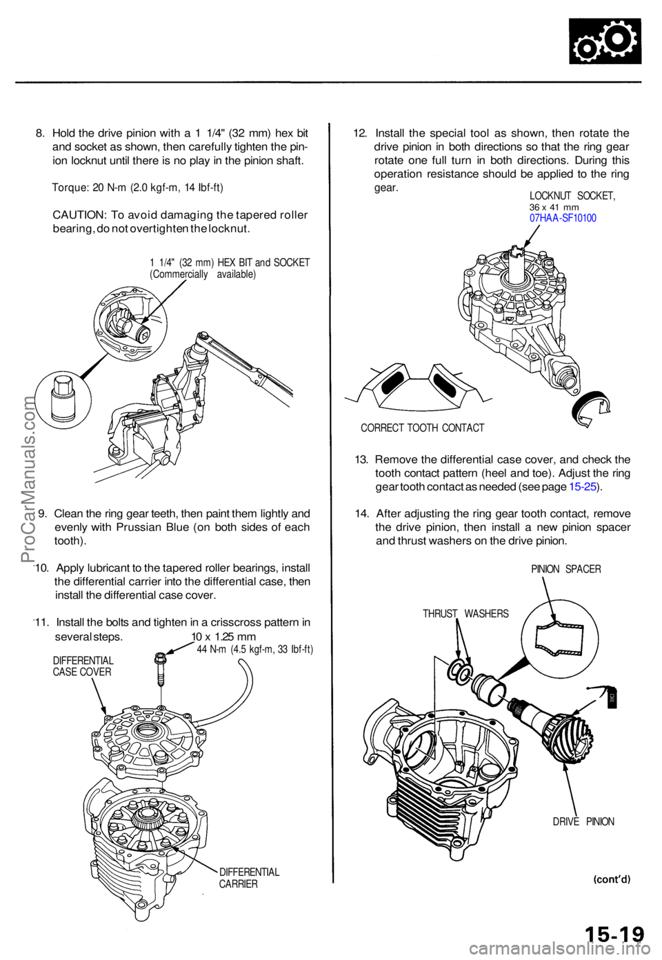
8. Hol d th e driv e pinio n wit h a 1 1/4 " (3 2 mm ) he x bi t
an d socke t a s shown , the n carefull y tighte n th e pin -
io n locknu t unti l ther e is n o pla y in th e pinio n shaft .
Torque : 2 0 N- m (2. 0 kgf-m , 1 4 Ibf-ft )
CAUTION : T o avoi d damagin g th e tapere d rolle r
bearing , d o no t overtighte n th e locknut .
1 1/4 " (3 2 mm ) HE X BI T an d SOCKE T
(Commerciall y available )
DIFFERENTIA L
CARRIE R
12. Instal l th e specia l too l a s shown , the n rotat e th e
driv e pinio n in bot h direction s s o tha t th e rin g gea r
rotat e on e ful l tur n i n bot h directions . Durin g thi s
operatio n resistanc e shoul d b e applie d t o th e rin g
gear .LOCKNU T SOCKET ,36 x 41 m m07HA A-SF1010 0
CORREC T TOOT H CONTAC T
13. Remov e th e differentia l cas e cover , an d chec k th e
toot h contac t patter n (hee l an d toe) . Adjus t th e rin g
gea r toot h contac t a s neede d (se e pag e 15-25 ).
14 . Afte r adjustin g th e rin g gea r toot h contact , remov e
th e driv e pinion , the n instal l a ne w pinio n space r
an d thrus t washer s o n th e driv e pinion .
PINION SPACE R
THRUS T WASHER S
DRIVE PINIO N
9. Clea n th e rin g gea r teeth , the n pain t the m lightl y an d
evenl y wit h Prussia n Blu e (o n bot h side s o f eac h
tooth) .
10 . Appl y lubrican t t o th e tapered roller bearings , instal l
th e differentia l carrie r int o th e differentia l case , the n
instal l th e differentia l cas e cover .
11 . Instal l th e bolt s an d tighte n in a crisscros s patter n in
severa l steps . 10 x 1.2 5 m m
44 N- m (4. 5 kgf-m , 3 3 Ibf-ft )
DIFFERENTIA L
CAS E COVE R
ProCarManuals.com