Page 1329 of 1954

Doors Mirrors
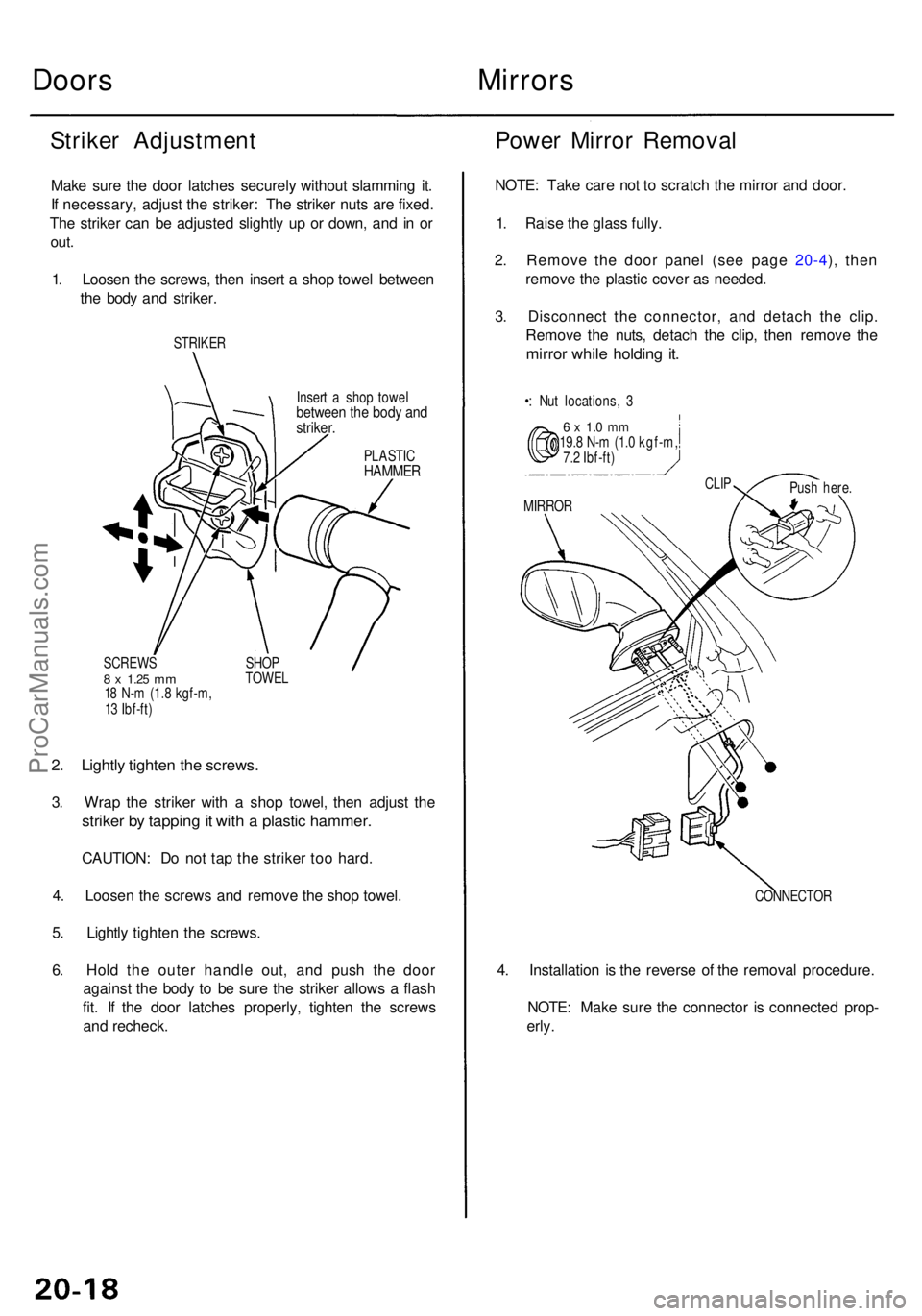
Striker Adjustmen t
Make sur e th e doo r latche s securel y withou t slammin g it .
I f necessary , adjus t th e striker : Th e strike r nut s ar e fixed .
Th e strike r ca n b e adjuste d slightl y u p o r down , an d i n o r
out .
1. Loose n th e screws , the n inser t a sho p towe l betwee n
th e bod y an d striker .
STRIKE R
PLASTICHAMME R
2. Lightl y tighte n th e screws .
3. Wra p th e strike r wit h a sho p towel , the n adjus t th e
strike r b y tappin g it wit h a plasti c hammer .
CAUTION : D o no t ta p th e strike r to o hard .
4 . Loose n th e screw s an d remov e th e sho p towel .
5 . Lightl y tighte n th e screws .
6 . Hol d th e oute r handl e out , an d pus h th e doo r
agains t th e bod y t o b e sur e th e strike r allow s a flas h
fit . I f th e doo r latche s properly , tighte n th e screw s
an d recheck .
Power Mirro r Remova l
NOTE: Tak e car e no t t o scratc h th e mirro r an d door .
1 . Rais e th e glas s fully .
2 . Remov e th e doo r pane l (se e pag e 20-4 ), the n
remov e th e plasti c cove r a s needed .
3 . Disconnec t th e connector , an d detac h th e clip .
Remov e th e nuts , detac h th e clip , the n remov e th e
mirro r whil e holdin g it .
•: Nu t locations , 3
6 x 1. 0 m m19. 8 N- m (1. 0 kgf-m ,
7. 2 Ibf-ft )
CONNECTOR
4. Installatio n i s th e revers e o f th e remova l procedure .
NOTE : Mak e sur e th e connecto r i s connecte d prop -
erly .
Inser t a sho p towe lbetwee n th e bod y an dstriker .
MIRRO R
CLIPPus h here .
SCREW S
8 x 1.2 5 mm18 N- m (1. 8 kgf-m ,
1 3 Ibf-ft ) SHO
P
TOWE L
ProCarManuals.com
Page 1352 of 1954

Moonroof
Guide Rails/Cabl e Assembl y Replacemen t (cont'd )
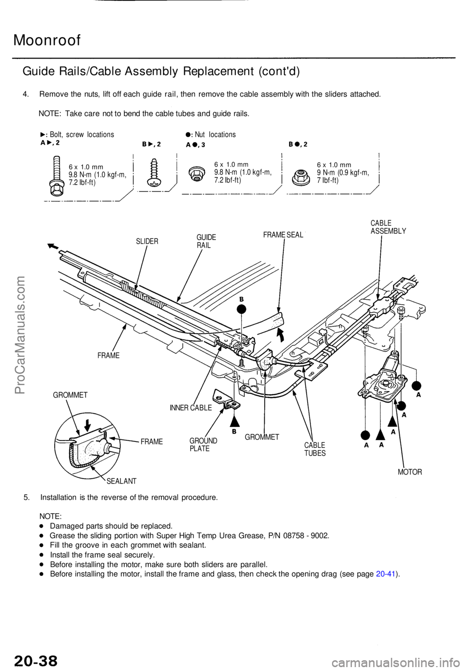
4. Remov e th e nuts , lif t of f eac h guid e rail , the n remov e th e cabl e assembly with th e slider s attached .
NOTE : Tak e car e no t t o ben d th e cabl e tube s an d guid e rails .
Bolt, scre w location s
6 x 1. 0 m m9.8 N- m (1. 0 kgf-m ,
7. 2 Ibf-ft ) Nu
t location s
6 x 1. 0 m m9.8 N- m (1. 0 kgf-m ,
7. 2 Ibf-ft )6 x 1. 0 m m9 N- m (0. 9 kgf-m ,
7 Ibf-ft )
SLIDE RGUIDERAIL
FRAM E SEA L
FRAM E
GROMME T
FRAME GROUN
DPLATECABL ETUBES
CABL EASSEMBL Y
MOTOR
SEALAN T
5. Installatio n i s th e revers e o f th e remova l procedure .
NOTE:
Damage d part s shoul d b e replaced .
Greas e th e slidin g portio n wit h Supe r Hig h Tem p Ure a Grease , P/ N 0875 8 - 9002 .
Fil l th e groov e i n eac h gromme t wit h sealant .
Instal l th e fram e sea l securely .
Befor e installin g th e motor , mak e sur e bot h slider s ar e parallel .
Befor e installin g th e motor , instal l th e fram e an d glass , the n chec k th e openin g dra g (se e pag e 20-41 ).
INNE R CABL E
GROMME T
ProCarManuals.com
Page 1353 of 1954
Switch Plat e Adjustmen t (Full y Close d Position/Aut o Sto p Position )
1. Remov e th e headline r (se e pag e 20-45 ).
2 . Usin g th e moonroo f wrench , close the glas s fully .
NOTE : Chec k th e glas s fi t t o th e roo f panel .
3 . Usin g a n open-en d wrench , loose n th e switc h plat e A mountin g bolts .
4 . Adjus t positio n o f switc h plat e A (switc h cam ) a s shown .
NOTE:
Move switc h plat e A a little a t a time , the n secur e switc h plat e A at th e positio n wher e th e switc h ca m contact s th e
close d positio n switc h ( a fain t clic k is heard) .
Chec k tha t switc h plat e A contact s th e cabl e bracket .
CABLE BRACKE T CLOSEDPOSITIO NSWITCH
OPEN-EN DWRENCH SWITC
H PLAT E A
Forwar d
SLIDER
SWITC H
PLAT E A
INNE R CABL E EN D
SWITC H CA M
CABL E BRACKE T
SWITCH
PLAT E A
GUID E PLAT E
CABLEBRACKE TBOLTS
GLAS S
ProCarManuals.com
Page 1354 of 1954
Moonroof
Switch Plate Adjustment (Fully Closed Position/Auto Stop Position) (cont'd)
5. Using the moonroof wrench, open the glass to the auto stop position as shown.
6. Using an open-end wrench, loosen the switch plate B mounting bolts.
7. Adjust position of switch plate B (switch cam) as shown.
NOTE:
Move switch plate B a little at a time, then secure switch plate B at the position where the switch cam contacts the
auto stop position switch (a faint click is heard).
Check that switch plate B contacts the cable bracket.
SWITCH CAM
INNER CABLE END
SWITCH
PLATE B
AUTO
STOP
POSITION
SWITCH
OPEN-END
WRENCH
SWITCH PLATE B
Forward
CABLE BRACKET
CABLE
BRACKET
BOLTS
GLASS
130 mm
(5.1 in.)
8. Check the operation of the glass (from the tilt-up position to the fully closed position, from the fully opened position
to the auto stop position, from the auto stop position to the fully closed position) by operating the moonroof switch.
CABLE BRACKETProCarManuals.com
Page 1357 of 1954

Interior Tri m
Remova l
CAUTION :
Pu t o n glove s to protec t you r hands .
Whe n pryin g wit h a flat-ti p screwdriver , wra p it wit h protectiv e tap e t o preven t damage .
NOTE : Tak e car e no t t o ben d o r scratc h th e tri m an d panels .
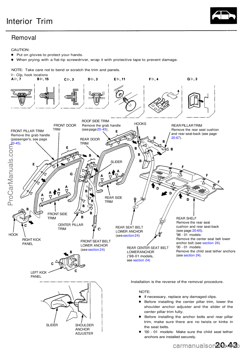
: Clip , hoo k location s
ROOF SID E TRI M
FRON T DOO R Remov e th e gra b handl e
HOOK S
FRONT PILLA R TRIM TRIM
Remov e th e gra b handl e
(passenger's , se e pag e
20-45 ).
(se e pag e 20-45 ). REA
R PILLA R TRI M
Remov e th e rea r sea t cushio n
an d rea r seat-bac k (se e pag e
20-67 ).
HOO K
RIGH T KIC KPANE L
LEFT KIC KPANE L
FRON T SEA T BEL TLOWE R ANCHO R(see sectio n 24 ) REA R CENTE R SEA T BEL TLOWE R ANCHO R('98-01 models ,see sectio n 24 )
REA R SHEL FRemov e th e rea r sea t
cushio n an d rea r seat-bac k
(se e pag e 20-65 ).
'9 8 - 0 1 models :
Remov e th e cente r sea t bel t lowe r
ancho r bol t (se e sectio n 24 ).
'0 0 - 0 1 models :
Remov e th e chil d sea t tethe r anchor s
(se e sectio n 24 ).
SLIDE RSHOULDE RANCHORADJUSTE R
Installation i s th e revers e o f th e remova l procedure .
NOTE:
If necessary , replac e an y damage d clips .
Befor e installin g th e cente r pilla r trim , lowe r th e
shoulde r ancho r adjuste r an d th e slide r o f th e
cente r pilla r tri m fully .
Befor e installin g th e ancho r bolt s an d rea r pilla r
trim , mak e sur e ther e ar e n o twist s o r kink s i n
th e sea t belts .
'0 0 - 0 1 models : Mak e sur e th e chil d sea t tethe r
anchor s ar e installe d securely .
REAR SEA T BEL TLOWE R ANCHO R(see sectio n 24 )
CENTE R PILLA RTRIM
FRON
T SID E
TRIM
REA R SID ETRIM
SLIDE R
REAR DOO RTRIM
ProCarManuals.com
Page 1360 of 1954
Headliner
Removal (cont'd )
5. Remov e th e clip s an d roo f trim , detac h th e rea r
clips , the n remov e th e headliner .
Clip location s
FASTENE R
HEADLINE R
JOINTROO FTRIM
6. Remov e th e headline r throug h th e passenger' s doo r
opening .
7. Installatio n i s th e revers e o f th e remova l procedure .
NOTE:
When insertin g th e headline r throug h th e doo r
opening , b e carefu l no t t o fol d o r ben d it . Also ,
b e carefu l no t t o scratc h th e body .
Chec k tha t bot h side s o f th e headline r ar e
securel y attache d t o th e trim .
Whe n installin g th e roo f trim , instal l th e join t
towar d th e rear .
ProCarManuals.com
Page 1378 of 1954
Pull bac k th e edg e o f th e seat-bac k cove r al l th e wa y
around , releas e th e clips , an d remov e th e seat-bac k
cover .
'9 6 - 9 8 model s
SEAT-BAC KCOVERCLIP
'99 - 0 1 model s
CLIP
SEAT-BAC KCOVER
7. Installatio n i s th e revers e o f th e remova l procedure .
NOTE:
To preven t wrinkle s whe n installin g a seat-bac k
cover , mak e sur e th e materia l i s stretche d evenl y
ove r th e pa d befor e securin g th e hook s an d clips .
Replac e th e release d clip s wit h ne w ones .
Use onl y origina l Acur a replacemen t seat-bac k
cover s ('9 9 - 0 1 models) .
ProCarManuals.com
Page 1379 of 1954
Front Sea t
Seat Cove r Replacemen t (cont'd )
Seat cushio n cove r removal :
1 . Remov e th e sea t cushio n (se e page s 20-58 , 20-59 ).
2 . Remov e th e clip s an d hook s fro m unde r th e sea t
cushion , the n remov e th e sea t cushio n cove r wit h
th e pa d fro m th e sea t cushio n frame .
HOOKS
HOOK S HOOK
S
PADCLIP S SEA
T CUSHIO N
FRAM E
3. Pul l bac k th e edg e o f th e sea t cushio n cove r al l th e
wa y around , releas e th e clips , an d remov e th e sea t
cushio n cover .
CLIP SEA
T CUSHIO NCOVER
4. Installatio n is th e revers e o f th e remova l procedure .
NOTE:
To preven t wrinkle s whe n installin g a sea t cush -
io n cover , mak e sur e th e materia l i s stretche d
evenl y ove r th e pa d befor e securin g th e clip s an d
hooks .
Replac e th e release d clip s wit h ne w ones .
SEATCOVE R
UPHOLSTER Y RIN G PLIER S
(Commerciall y available )
NE W CLI P
PAD
WIR E (Pa d side )WIRE(Cove r side )
ProCarManuals.com