Page 1273 of 1954
Troubleshooting
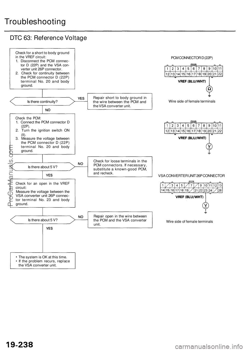
DTC 63: Reference Voltage
Check for a short to body ground
in the VREF circuit:
1. Disconnect the PCM connec-
tor D
(22P)
and the VSA
con-
verter unit 26P connector.
2. Check for continuity between
the PCM connector D (22P)
terminal No. 20 and body
ground.
Is there continuity?
Is there about 5 V?
Check for an open in the VREF
circuit:
Measure the voltage between the
VSA converter unit 26P connec-
tor terminal No. 23 and body
ground.
Is there about 5 V?
The system is OK at this time.
If the problem recurs, replace
the VSA converter unit.
Repair short to body ground in
the wire between the PCM and
the VSA converter unit.
Check for loose terminals in the
PCM connectors. If necessary,
substitute a known-good PCM,
and recheck.
PCM CONNECTOR D (22P)
Wire side of female terminals
VSA CONVERTER UNIT 26P CONNECTOR
Repair open in the wire between
the PCM and the VSA converter
unit.
Wire side of female terminals
Check the PCM:
1. Connect the PCM connector D
(22P).
2. Turn the ignition switch ON
(II).
3. Measure the voltage between
the PCM connector D (22P)
terminal No. 20 and body
ground.ProCarManuals.com
Page 1292 of 1954
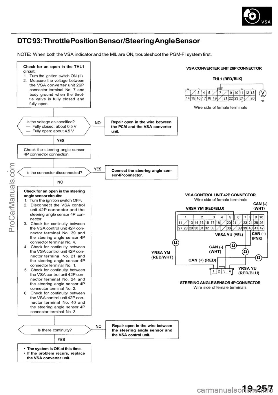
DTC 93: Throttle Position Sensor/Steering Angle Sensor
NOTE: When both the VSA indicator and the MIL are ON, troubleshoot the PGM-FI system first.
Check for an open in the THL1circuit:1. Turn the ignition switch ON (II).
2. Measure the voltage between
the VSA converter unit 26Pconnector terminal No. 7 and body ground when the throt-
tle valve is fully closed and
fully open.
Is the voltage as specified?
— Fully closed: about 0.5 V
— Fully open: about 4.5 V
Check the steering angle sensor
4P connector connection.
Is the connector disconnected?
Check for an open in the steering
angle sensor circuits:
1. Turn the ignition switch OFF.2. Disconnect the VSA controlunit 42P connector and thesteering angle sensor 4P con-nector.
3. Check for continuity between
the VSA control unit 42P con-nector terminal No. 39 and
the steering angle sensor 4P
connector terminal No. 4.
4. Check for continuity between
the VSA control unit 42P con-nector t e r m i n a l No. 21 and
the steering angle sensor 4P
connector terminal No. 1.
5. Check for continuity between
the VSA control unit 42P con-nector terminal No. 24 and
the steering angle sensor 4P
connector terminal No. 2.
6. Check for continuity between
the VSA control unit 42P con-nector terminal No. 40 and
the steering angle sensor 4P
connector terminal No. 3.
Is there continuity?
The system is OK at this time. If the problem recurs, replace
the VSA converter unit. VSA CONVERTER UNIT 26P CONNECTOR
Repair open in the wire between
the PCM and the VSA converter unit.
Connect the steering angle sen-
sor 4P connector. VSA CONTROL UNIT 42P CONNECTORWire side of female terminals
STEERING ANGLE SENSOR 4P CONNECTOR Wire side of female terminals
Repair open in the wire between
the steering angle sensor and
the VSA control unit. Wire side of female terminals
YRSA YM
(RED/WHT) CAN (-)
(WHT)
CAN (+) (RED) YRSA YU
(RED/BLU)
ProCarManuals.com
Page 1294 of 1954
(From pag e 19-258 )
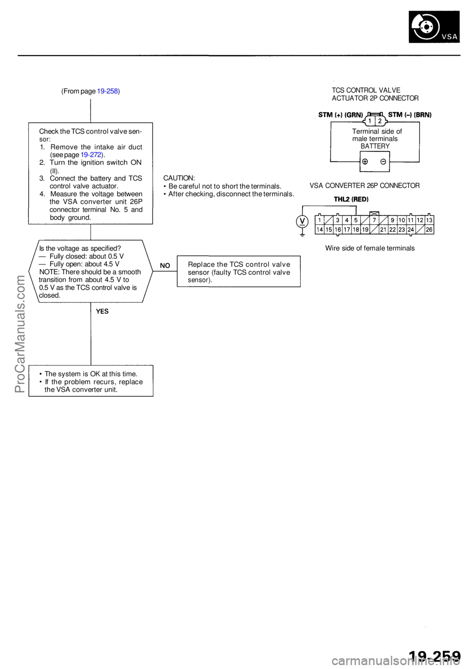
Chec k th e TC S contro l valv e sen -
sor:1. Remov e th e intak e ai r duc t
(se e pag e 19-272 ).
2 . Tur n th e ignitio n switc h O N(II).3. Connec t th e batter y an d TC S
contro l valv e actuator .
4 . Measur e th e voltag e betwee n
th e VS A converte r uni t 26 P
connecto r termina l No . 5 an d
bod y ground .
TCS CONTRO L VALV E
ACTUATO R 2 P CONNECTO R
Terminal sid e o f
mal e terminal s
BATTER Y
CAUTION :
• B e carefu l no t t o shor t th e terminals .
• Afte r checking , disconnec t th e terminals .VSA CONVERTE R 26 P CONNECTO R
Is th e voltag e a s specified ?
— Full y closed : abou t 0. 5 V
— Full y open : abou t 4. 5 V
NOTE : Ther e shoul d b e a smoot h
transitio n fro m abou t 4. 5 V to
0. 5 V as th e TC S contro l valv e is
closed . Wir
e sid e o f femal e terminal s
Replac e th e TC S contro l valv e
senso r (fault y TC S contro l valv e
sensor) .
The syste m is O K a t thi s time .
I f th e proble m recurs , replac e
th e VS A converte r unit .
ProCarManuals.com
Page 1311 of 1954
Doors
Front Doo r Inde xSASH TRI M
Removal , pag e
20-8OUTE RWEATHERSTRI PMIRRORRemoval , pag e20-18INNE R SAS HTRIMRemoval , pag e20-8
INNE RMOLDIN G
OUTERMOLDIN G
FRONTCORNE RTRIM
HING E
PLASTI C
COVER
MEMOR Y
CONTRO L
UNITTWEETE R(for som e models )
COURTES Y
LIGH T
SPEAKE RCOVER
CAP
POWE R WINDO W
SWITC HPOWERWINDO WSWITCHDOOR POCKE T
LOWE
R PA D
ARMRES
T
PAD
SWITC HTRIM
POWE R SEA T
MEMOR Y SWITC H
(driver's )
POWER MIRRO R
SWITCH(driver's )TRUN
K LI D
OPENE RSWITCH
(driver's ) Passenger's
:
SWITC HPANEL
SWITC HPANEL
DOORPOCKE T
DOOR PANE L
Removal , pag e 20- 4
DOO
R
PROTECTO R
TWEETERGRILLE
TWEETE R(for som e models )
STO
P
LOC
K KNO B
COVE R
DYNAMI CDAMPER
SWITCHBRACKE TSPEAKERSPACER
ADAPTE R
DETENTROD
SECURIT Y
INDICATO R
(driver's )
INNE
R
WEATHERSTRI P
DOORAdjustment ,page 20-1 7
ProCarManuals.com
Page 1313 of 1954
Doors
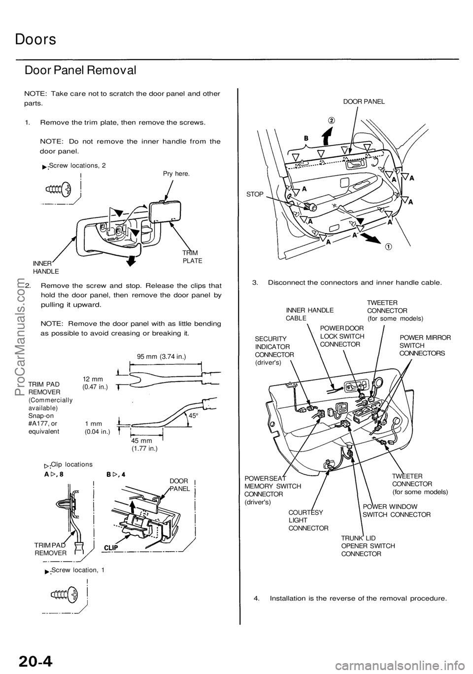
Door Pane l Remova l
NOTE: Tak e car e no t t o scratc h th e doo r pane l an d othe r
parts.
1. Remov e th e tri m plate , the n remov e th e screws .
NOTE : D o no t remov e th e inne r handl e fro m th e
doo r panel .
Screw locations , 2
Pry here .
INNE R
HANDL E TRI
M
PLAT E
2. Remov e th e scre w an d stop . Releas e th e clip s tha t
hol d th e doo r panel , the n remov e th e doo r pane l b y
pullin g it upward .
NOTE: Remov e th e doo r pane l wit h a s littl e bendin g
a s possibl e to avoi d creasin g o r breakin g it .
TRI M PA DREMOVE R(Commerciall yavailable)Snap-on
#A177 , o r
equivalen t
12 m m(0.4 7 in. )
1 m m(0.0 4 in. )
45 m m(1.7 7 in. )
Clip location s
DOORPANE L
TRIM PA DREMOVE R
DOOR PANE L
STO P
3. Disconnec t th e connector s an d inne r handl e cable .
SECURIT YINDICATO R
CONNECTO R
(driver's )
POWE R SEA T
MEMOR Y SWITC H
CONNECTO R
(driver's)
COURTES YLIGHT
CONNECTO R
TWEETERCONNECTO R(for som e models )
POWER WINDO W
SWITC H CONNECTO R
TRUN K LI D
OPENE R SWITC H
CONNECTO R
4. Installatio n i s th e revers e o f th e remova l procedure .
INNER HANDL ECABLE
POWE R DOO R
LOC K SWITC H
CONNECTO RTWEETE
R
CONNECTO R
(fo r som e models )
POWE R MIRRO R
SWITC H
CONNECTOR S
Screw location , 1
9 5 m m (3.7 4 in. )
45°
ProCarManuals.com
Page 1315 of 1954
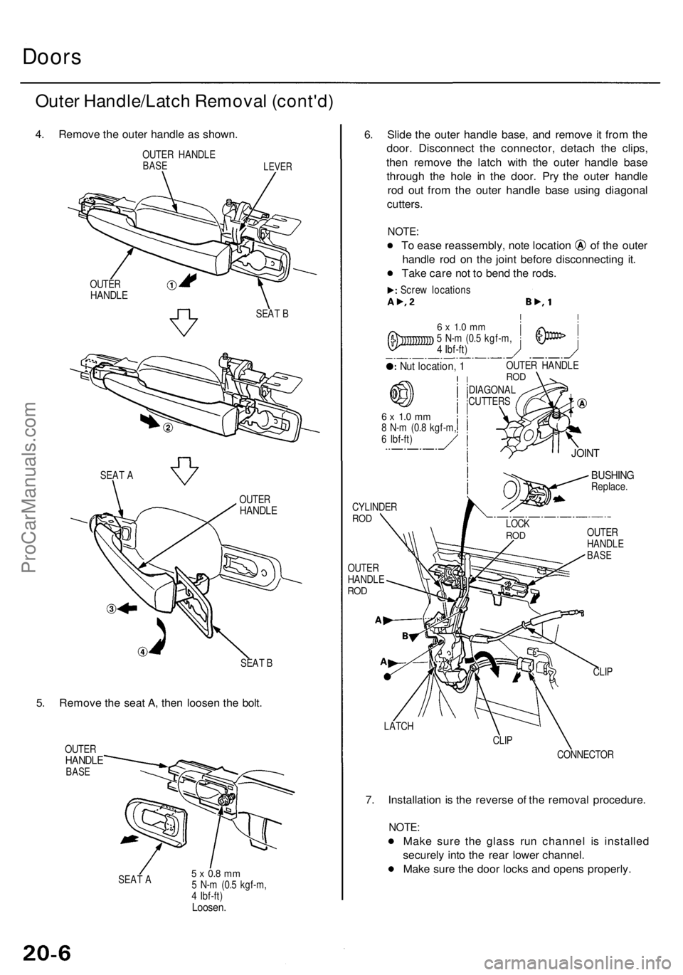
Doors
Outer Handle/Latc h Remova l (cont'd )
4. Remov e th e oute r handl e a s shown .
OUTER HANDL EBASELEVE R
SEAT B
5. Remov e th e sea t A , the n loose n th e bolt .
OUTE RHANDL EBASE
SEAT A5 x 0. 8 m m5 N- m (0. 5 kgf-m ,
4 Ibf-ft )
Loosen .
6. Slid e th e oute r handl e base , an d remov e i t fro m th e
door . Disconnec t th e connector , detac h th e clips ,
the n remov e th e latc h wit h th e oute r handl e bas e
throug h th e hol e i n th e door . Pr y th e oute r handl e
ro d ou t fro m th e oute r handl e bas e usin g diagona l
cutters .
NOTE:
To eas e reassembly , not e locatio n o f th e oute r
handl e ro d o n th e join t befor e disconnectin g it .
Tak e car e no t t o ben d th e rods .
Screw location s
6 x 1. 0 m m5 N- m (0. 5 kgf-m ,
4 Ibf-ft )
Nut location , 1OUTE R HANDL EROD
DIAGONA L
CUTTER S
6 x 1. 0 m m8 N- m (0. 8 kgf-m ,6 Ibf-ft )
CYLINDE RROD
OUTE R
HANDL E
ROD
BUSHIN GReplace .
OUTE R
HANDL E
BASE
CLIP
LATC H
CLIP
CONNECTO R
7. Installatio n i s th e revers e o f th e remova l procedure .
NOTE:
Make sur e th e glas s ru n channe l i s installe d
securel y int o th e rea r lowe r channel .
Mak e sur e th e doo r lock s an d open s properly .
SEAT B
OUTE
R
HANDL E
OUTERHANDL E
SEAT A
LOC KROD
JOIN T
ProCarManuals.com
Page 1317 of 1954
Doors
Sash Tri m Remova l
NOTE: Lowe r th e glas s fully .
1 . Remove :
Doo r pane l (se e pag e 20-4 )
Inne r sas h tri m
2 . Remov e th e glas s ru n channe l an d oute r weather -
stri p a s needed . Remov e an d loose n th e screws ,
the n remov e th e sas h trim .
Screw location s
INNER SAS HTRIMOUTE RWEATHERSTRI P
GLASS RU NCHANNE L
SASH TRI M
SAS HTRIM
GLAS S RU NCHANNE L
Loosen.
3. Installatio n i s th e revers e o f th e remova l procedure .
NOTE : Mak e sur e th e glas s ru n channe l an d oute r
weatherstri p ar e installe d securely .
Inner Sas h Tri m Remova l
NOTE:
Lower th e glas s fully .
Tak e car e no t t o scratc h th e inne r sas h trim .
Remov e th e doo r pane l (se e pag e 20-4 ).
Cli p location s
INNER SAS HTRIM
Installatio n i s th e revers e o f th e remova l procedure .
NOTE : I f necessary , replac e an y damage d clips .
GROMME T
CLIP
INNE RWEATHERSTRI P
GLASSRUNCHANNE L
INNERSASH TRI M
ProCarManuals.com
Page 1325 of 1954
Sash Tri m Remova l
NOTE: Lowe r th e glas s fully .
1 . Remove :
Doo r pane l (se e pag e 20-11 )
Inne r sas h tri m
2 . Remov e th e glas s ru n channe l an d oute r weather -
stri p a s needed . Remov e an d loose n th e screws ,
the n remov e th e sas h trim .
Scre w location s
INNER SAS H
TRI M
OUTE R
WEATHERSTRI P
SAS H TRI M GLAS
S RU N
CHANNE L
SAS H
TRI M
GROMMET
GLAS S RU N
CHANNE L
Loosen .
3. Installatio n i s th e revers e o f th e remova l procedure .
NOTE : Mak e sur e th e glas s ru n channe l an d oute r
weatherstri p ar e installe d securely .
Inner Sas h Tri m Remova l
NOTE:
Lower th e glas s fully .
Tak e car e no t t o scratc h th e inne r sas h trim .
Remov e th e doo r pane l (se e pag e 20-11 ).
Cli p location s
INNE R
WEATHERSTRI P
CLIP
GLAS S RU NCHANNE L
INNER SAS H
TRI M
INNE R SAS H
TRI M
Installatio n i s th e revers e o f th e remova l procedure .
NOTE : I f necessary , replac e an y damage d clips .
ProCarManuals.com