Page 1067 of 1954
Rear Brak e Dis c
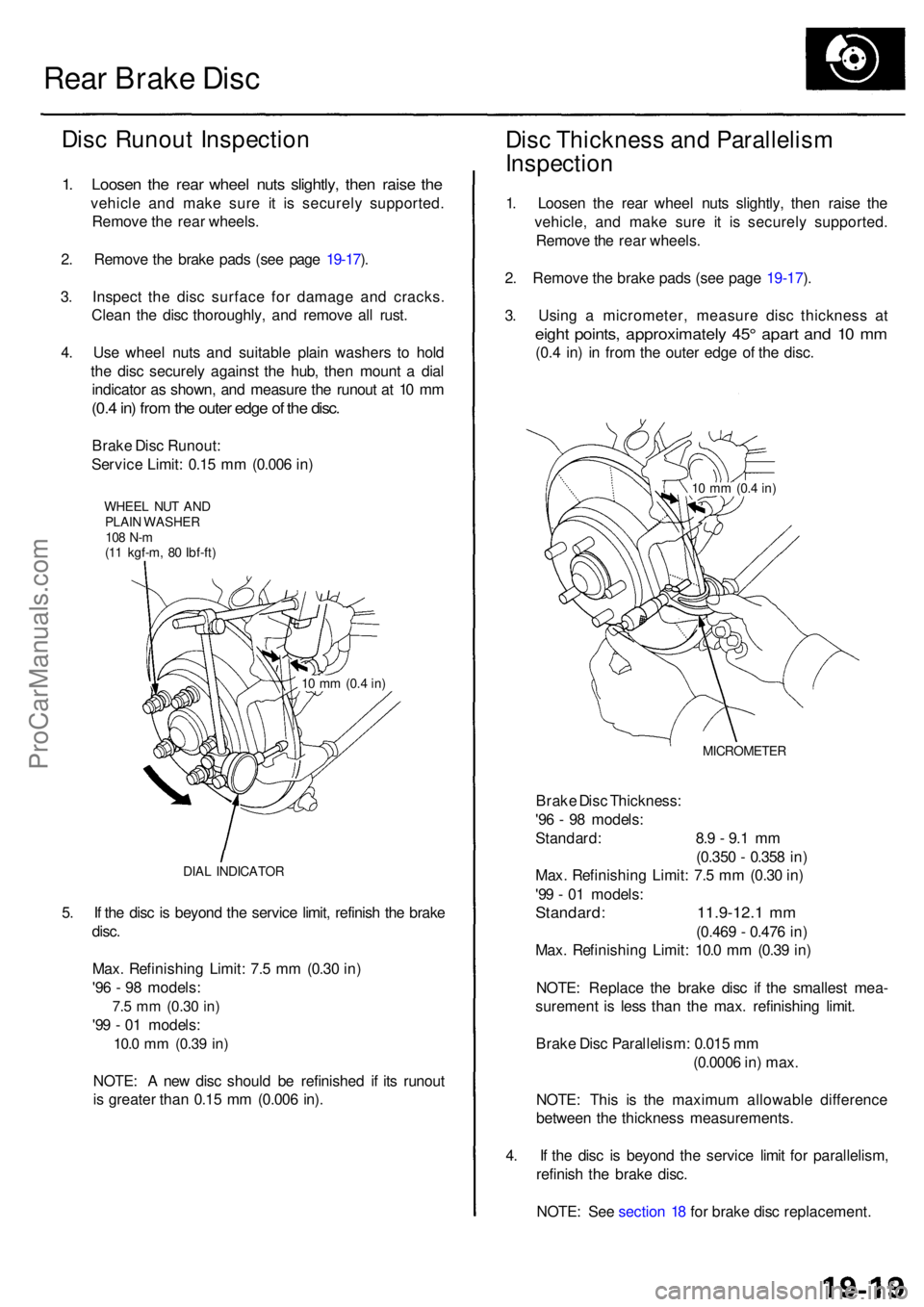
Disc Runou t Inspectio n
1. Loose n th e rea r whee l nut s slightly , the n rais e th e
vehicl e an d mak e sur e i t i s securel y supported .
Remov e th e rea r wheels .
2 . Remov e th e brak e pad s (se e pag e 19-17 ).
3 . Inspec t th e dis c surfac e fo r damag e an d cracks .
Clea n th e dis c thoroughly , an d remov e al l rust .
4 . Us e whee l nut s an d suitabl e plai n washer s t o hol d
th e dis c securel y agains t th e hub , the n moun t a dia l
indicato r a s shown , an d measur e th e runou t a t 1 0 m m
(0.4 in ) fro m th e oute r edg e o f th e disc .
Brak e Dis c Runout :
Servic e Limit : 0.1 5 m m (0.00 6 in )
WHEE L NU T AN DPLAI N WASHE R108 N- m(11 kgf-m , 8 0 Ibf-ft )
DIA L INDICATO R
5. I f th e dis c i s beyon d th e servic e limit , refinis h th e brak e
disc .
Max . Refinishin g Limit : 7. 5 m m (0.3 0 in )
'9 6 - 9 8 models :
7.5 m m (0.3 0 in)
'99 - 0 1 models :
10.0 mm (0.3 9 in)
NOTE : A ne w dis c shoul d b e refinishe d i f it s runou t
i s greate r tha n 0.1 5 m m (0.00 6 in) .
Dis c Thicknes s an d Parallelis m
Inspectio n
1. Loose n th e rea r whee l nut s slightly , the n rais e th e
vehicle , an d mak e sur e i t i s securel y supported .
Remov e th e rea r wheels .
2 . Remov e th e brak e pad s (se e pag e 19-17 ).
3 . Usin g a micrometer , measur e dis c thicknes s a t
eigh t points , approximatel y 45 ° apar t an d 1 0 m m
(0.4 in ) i n fro m th e oute r edg e o f th e disc .
MICROMETE R
Brake Dis c Thickness :
'9 6 - 9 8 models :
Standard : 8. 9 - 9. 1 m m
(0.35 0 - 0.35 8 in )
Max . Refinishin g Limit : 7. 5 m m (0.3 0 in )
'9 9 - 0 1 models :
Standard : 11.9-12. 1 m m
(0.46 9 - 0.47 6 in )
Max . Refinishin g Limit : 10. 0 m m (0.3 9 in )
NOTE : Replac e th e brak e dis c i f th e smalles t mea -
suremen t i s les s tha n th e max . refinishin g limit .
Brak e Dis c Parallelism : 0.01 5 m m
(0.000 6 in ) max .
NOTE : Thi s i s th e maximu m allowabl e differenc e
betwee n th e thicknes s measurements .
4 . I f th e dis c i s beyon d th e servic e limi t fo r parallelism ,
refinis h th e brak e disc .
NOTE : Se e sectio n 1 8 fo r brak e dis c replacement .
10 m m (0. 4 in)
10 m m (0. 4 in)
ProCarManuals.com
Page 1070 of 1954
Parking Brak e
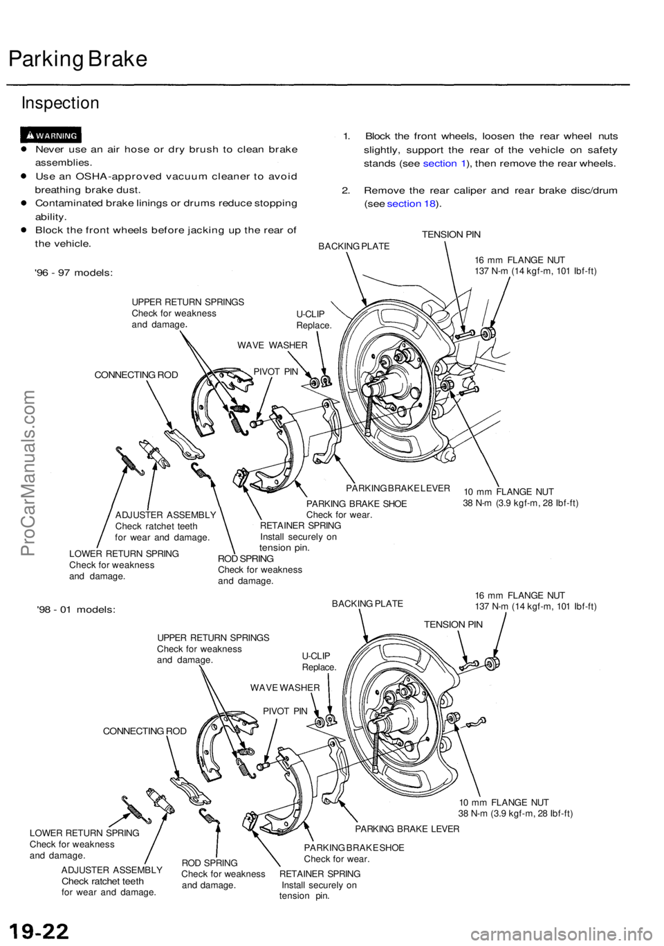
Inspectio n
Never us e a n ai r hos e o r dr y brus h t o clea n brak e
assemblies .
Use a n OSHA-approve d vacuu m cleane r t o avoi d
breathin g brak e dust .
Contaminate d brak e lining s o r drum s reduc e stoppin g
ability .
Bloc k th e fron t wheel s befor e jackin g u p th e rea r o f
th e vehicle . 1
. Bloc k th e fron t wheels , loose n th e rea r whee l nut s
slightly , suppor t th e rea r of the vehicl e o n safet y
stand s (se e sectio n 1 ), the n remov e th e rea r wheels .
2 . Remov e th e rea r calipe r an d rea r brak e disc/dru m
(se e sectio n 18 ).
TENSIO N PI NBACKIN G PLAT E
'96 - 9 7 models :
UPPER RETUR N SPRING S
Chec k fo r weaknes s
an d damag e
CONNECTIN G RO D
16 m m FLANG E NU T
13 7 N- m (1 4 kgf-m , 10 1 Ibf-ft )
ADJUSTE R ASSEMBL Y
Chec k ratche t teet h
fo r wea r an d damage .
LOWE R RETUR N SPRIN G
Chec k fo r weaknes s
an d damage . PARKIN
G BRAK E LEVE R
PARKIN G BRAK E SHO E
Chec k fo r wear .
RETAINE R SPRIN G
Instal l securel y o n
tensio n pin .ROD SPRIN GCheck fo r weaknes s
an d damage .
'98 - 0 1 models :BACKIN G PLAT E
UPPE R RETUR N SPRING S
Chec k fo r weaknes s
an d damage .
CONNECTIN G RO D
LOWE R RETUR N SPRIN G
Chec k fo r weaknes s
an d damage .
ADJUSTE R ASSEMBL Y
Check ratche t teet hfor wea r an d damage . 1
6 m m FLANG E NU T
13 7 N- m (1 4 kgf-m , 10 1 Ibf-ft )
1 0 m m FLANG E NU T
3 8 N- m (3. 9 kgf-m , 2 8 Ibf-ft )
PARKIN G BRAK E LEVE R
RO D SPRIN G PARKIN
G BRAK E SHO E
Chec k fo r wear .
Chec k fo r weaknes s RETAINE R SPRIN G
an d damage . Instal l securel y o n
tensio n pin .
PIVO
T PI N
WAV
E WASHE R
U-CLI
P
Replace .
WAV
E WASHE R
PIVO T PI NU-CLI
P
Replace .
TENSION PI N
10 m m FLANG E NU T
3 8 N- m (3. 9 kgf-m , 2 8 Ibf-ft )
ProCarManuals.com
Page 1073 of 1954
7. Remove the brake shoe by disconnecting the park-
ing brake cable from the parking brake lever.
PARKING BRAKE LEVER
PARKING BRAKE CABLE
8. Remove the wave washer, parking brake lever, and
pivot pin from the parking brake shoe by removing
the U-clip.
PARKING BRAKE SHOE
PIVOT PIN
PARKING BRAKE LEVER
U-CLIP WAVE WASHER
Replace.
9. Apply Molykote 44 MA grease to the sliding surface
of the pivot pin, and insert the pin into the parking
brake shoe.
10. Install the parking brake lever and wave washer on
the pivot pin, and secure them with a new U-clip.
NOTE: Pinch the new U-clip securely to prevent the
pivot pin from coming out of the parking brake shoe.
: Apply Molykote 44 MA grease
to sliding surface.
PARKING BRAKE SHOE
PIVOT PIN
PARKING BRAKE LEVER
WAVE WASHER
U-CLIP
Replace.
11. Connect the parking brake cable to the parking brake
lever.
PARKING BRAKE LEVER
PARKING BRAKE CABLEProCarManuals.com
Page 1074 of 1954
Parking Brake
Parking Brake Shoes Replacement (cont'd)
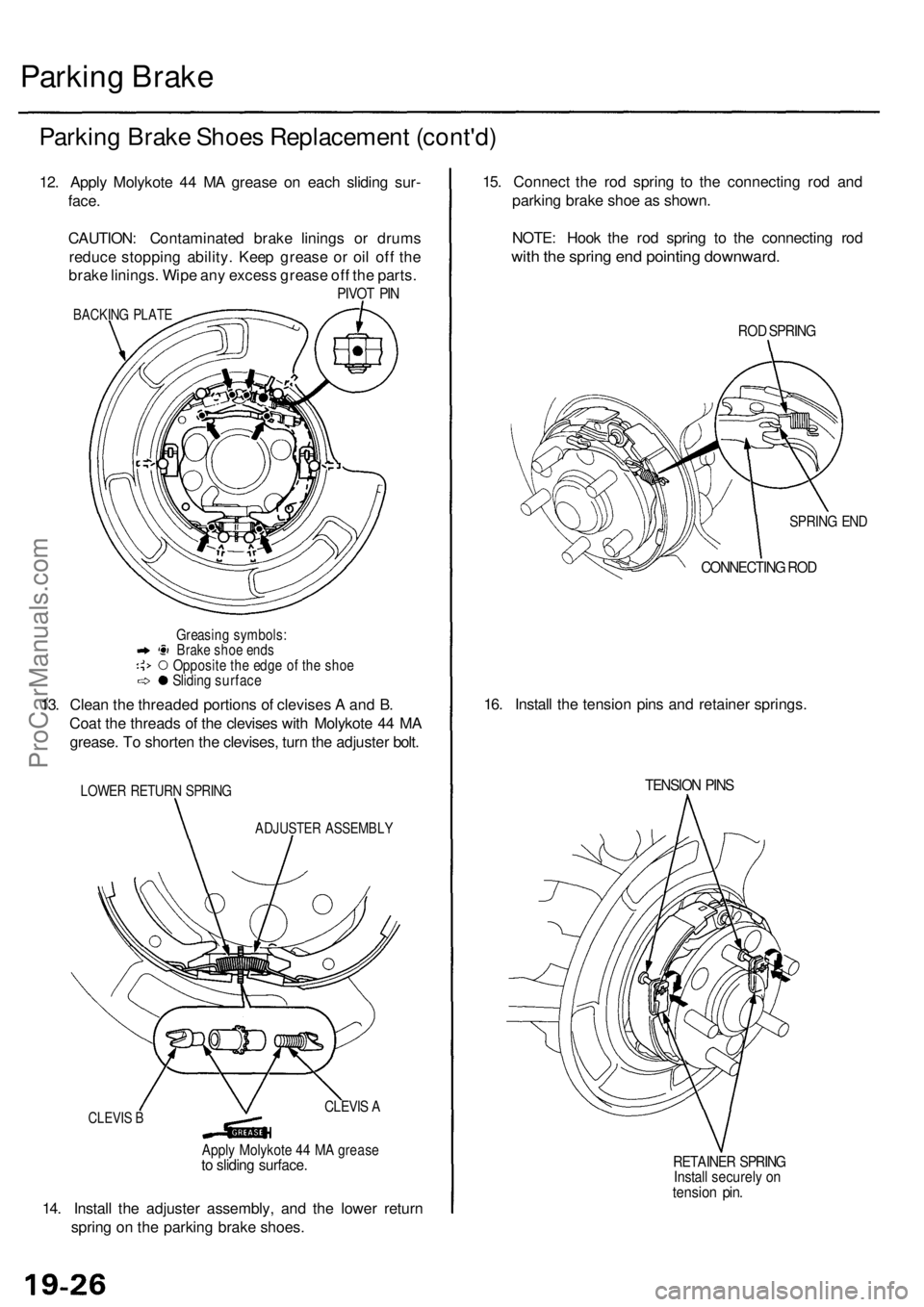
12. Apply Molykote 44 MA grease on each sliding sur-
face.
CAUTION: Contaminated brake linings or drums
reduce stopping ability. Keep grease or oil off the
brake linings. Wipe any excess grease off the parts.
PIVOT PIN
BACKING PLATE
Greasing symbols:
Brake shoe ends
Opposite the edge of the shoe
Sliding surface
13. Clean the threaded portions of clevises A and B.
Coat the threads of the clevises with Molykote 44 MA
grease. To shorten the clevises, turn the adjuster bolt.
LOWER RETURN SPRING
ADJUSTER ASSEMBLY
14. Install the adjuster assembly, and the lower return
spring on the parking brake shoes.
15. Connect the rod spring to the connecting rod and
parking brake shoe as shown.
NOTE: Hook the rod spring to the connecting rod
with the spring end pointing downward.
ROD SPRING
SPRING END
CONNECTING ROD
16. Install the tension pins and retainer springs.
TENSION PINS
RETAINER SPRING
Install securely on
tension pin.
CLEVIS B
CLEVIS A
Apply Molykote 44 MA grease
to sliding surface.ProCarManuals.com
Page 1081 of 1954
Component Locations
ABS CONTROL UNIT
MODULATOR UNIT
SERVICE CHECK CONNECTOR (2P)
ABS INSPECTION CONNECTOR (6P)
RIGHT-REAR WHEEL SENSOR
RIGHT-FRONT WHEEL
SENSOR CONNECTOR
RIGHT-FRONT
WHEEL SENSOR
LEFT-REAR WHEEL
SENSOR CONNECTOR
LEFT-REAR
WHEEL SENSOR
RIGHT-REAR WHEEL
SENSOR CONNECTOR
UNDER-HOOD
RELAY BOX B
UNDER-HOOD
FUSE/RELAY BOX
UNDER-DASH FUSE/RELAY BOX
LEFT-FRONT WHEEL SENSOR
LEFT-FRONT WHEEL
SENSOR CONNECTOR
GAUGE ASSEMBLY:
ABS INDICATOR LIGHT
UNDER-DASH FUSE/RELAY BOX:
METER
(7.5 A) FUSE
ABS B2
(15 A) FUSE
ABS B1
(20 A) FUSE
METER
(15 A) FUSE
BATTERY
(120 A) FUSE
ABS MOTOR (40 A) FUSE
IG SW (50 A) FUSE
UNDER-HOOD RELAY BOX C:
REAR FAIL-SAFE RELAY
METER RELAY
FRONT FAIL-SAFE RELAY
ABS
UNIT
(7.5 A) FUSE
STOP/HORN
(ISA) FUSE
ABS PUMP
MOTOR RELAY
UNDER-HOOD FUSE/RELAY BOX:
ECU
(20 A) FUSE
R/C MIRROR
(7.5 A) FUSEProCarManuals.com
Page 1190 of 1954
Component Locations
SERVICE CHECK CONNECTOR (2P)
ABS CONTROL UNIT
ECT SENSOR
TCS CONTROL VALVE
SENSOR
RIGHT-FRONT
WHEEL SENSOR
TCS CONTROL
VALVE ACTUATOR
LEFT-REAR
WHEEL SENSOR
GAUGE ASSEMBLY
ECU (PCM) (20 A) FUSE
UNDER-HOOD FUSE/RELAY BOX
BATTERY (120 A) FUSE
UNDER-HOOD RELAY BOX C
FAIL-SAFE RELAY
IG SW (50 A) FUSE
METER (15 A) FUSE
METER RELAY
TCS (15 A) FUSE
STOP/HORN
'96 - 98 models: (15 A) FUSE
'99 model: (20 A) FUSE
UNDER-HOOD FUSE/RELAY BOX
UNDER-HOOD RELAY BOX C
LEFT-FRONT WHEEL SENSOR
POWERTRAIN
CONTROL MODULE (PCM)
STEERING ANGLE SENSOR
RIGHT-REAR WHEEL SENSOR
TCS CONTROL UNIT
TCS/CRUISE SWITCH
UNDER-DASH FUSE/RELAY BOX
UNDER-DASH FUSE/RELAY BOX
METER (7.5 A) FUSE
TCS INDICATOR LIGHTProCarManuals.com
Page 1215 of 1954
Troubleshooting
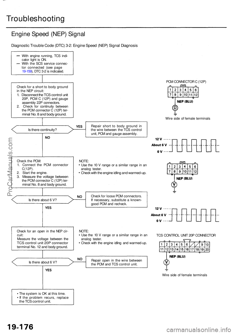
Engine Spee d (NEP ) Signa l
Diagnosti c Troubl e Cod e (DTC ) 3-2 : Engin e Spee d (NEP ) Signa l Diagnosi s
With engin e running , TC S indi -
cato r ligh t i s ON .
Wit h th e SC S servic e connec -
to r connecte d (se e pag e
19-159 ), DT C 3- 2 is indicated .
Chec k fo r a shor t t o bod y groun d
i n th e NE P circuit :
1. Disconnec t th e TC S contro l uni t20P , PC M C (12P ) an d gaug e
assembl y 22 P connectors .
2 . Chec k fo r continuit y betwee n
th e PC M connecto r C (12P ) ter -
mina l No . 8 an d bod y ground .
Is ther e continuity ?
Is ther e abou t 6 V ?
Chec k fo r a n ope n in th e NE P cir -
cuit :
Measur e th e voltag e betwee n th e
TC S contro l uni t 20 P connecto rterminal No . 1 2 an d bod y ground .
Is ther e abou t 6 V ?
Th e syste m is O K a t thi s time .
I f th e proble m recurs , replac e
the TC S contro l unit .
PCM CONNECTO R C (12P )
Wir e sid e o f femal e terminal s
Repai r shor t t o bod y groun d i n
th e wir e betwee n th e TC S contro l
unit , PC M an d gaug e assembly .
Chec k fo r loos e PC M connectors .
I f necessary , substitut e a known -
goo d PC M an d recheck .
NOTE :
Us e th e 1 0 V rang e o r a simila r rang e in a n
analo g tester .
Chec k wit h th e engin e idlin g an d warmed-up .TC
S CONTRO L UNI T 20 P CONNECTO R
Repai r ope n in th e wir e betwee n
th e PC M an d TC S contro l unit .
Wire sid e o f femal e terminal s
Chec
k th e PCM :
1 . Connec t th e PC M connecto r
C(12P).2. Star t th e engine .3. Measur e th e voltag e betwee nthe PC M connecto r C (12P ) ter -mina l No . 8 an d bod y ground .
Use th e 1 0 V rang e o r a simila r rang e in a n
analo g tester .
Check wit h th e engin e idlin g an d warmed-up .
NOTE:
ProCarManuals.com
Page 1216 of 1954
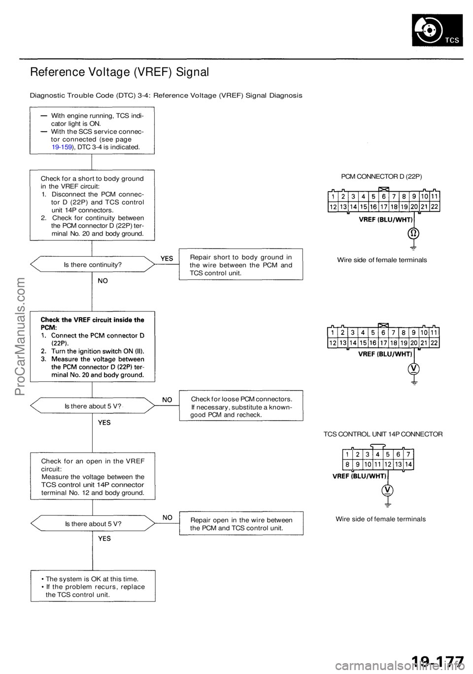
Reference Voltag e (VREF ) Signa l
Diagnosti c Troubl e Cod e (DTC ) 3-4 : Referenc e Voltag e (VREF ) Signa l Diagnosi s
With engin e running , TC S indi -
cato r ligh t i s ON .
Wit h th e SC S servic e connec -
to r connecte d (se e pag e
19-159 ), DT C 3- 4 is indicated .
Chec k fo r a shor t t o bod y groun d
i n th e VRE F circuit :
1 . Disconnec t th e PC M connec -
to r D (22P ) an d TC S contro l
uni t 14 P connectors .
2 . Chec k fo r continuit y betwee n
th e PC M connecto r D (22P ) ter -
mina l No . 2 0 an d bod y ground .
I s ther e continuity ?
I s ther e abou t 5 V ?
Chec k fo r a n ope n i n th e VRE F
circuit :
Measur e th e voltag e betwee n th e
TC S contro l uni t 14 P connecto rterminal No . 1 2 an d bod y ground .
I s ther e abou t 5 V ?
Th e syste m is O K a t thi s time .
I f th e proble m recurs , replac e
th e TC S contro l unit . PC
M CONNECTO R D (22P )
Repai r shor t t o bod y groun d i n
th e wir e betwee n th e PC M an d
TC S contro l unit .
Wire sid e o f femal e terminal s
Check fo r loos e PC M connectors .
I f necessary , substitut e a known -
good PC M an d recheck .
TCS CONTRO L UNI T 14 P CONNECTO R
Repai r ope n in th e wir e betwee n
th e PC M an d TC S contro l unit . Wir
e sid e o f femal e terminal s
ProCarManuals.com