1996 ACURA RL KA9 ECU
[x] Cancel search: ECUPage 921 of 1954

Differential Assembl y
Inspection
To establis h a startin g poin t befor e disassembly , inspec t
the following :
Ring gea r backlas h
Tota l bearin g preloa d
Gea r toot h contac t
NOTE:
Be sur e th e differential is a t roo m temperatur e befor e
inspecting .
Recor d th e result s o f th e preliminar y inspections .
Thi s informatio n wil l b e helpfu l durin g reassembly .
Rin g gea r backlas h
1 . Remov e th e oi l fille r plu g an d th e oi l seal .
OIL SEA LReplace .
OIL FILLE R PLU G
4 4 N- m (4. 5 kgf-m , 3 3 Ibf-ft )
WASHE R
Replace .
BENCHVISE LOCKNU
T SOCKET ,
36 x 4 1 m m07HAA-SF1010 0
3. Alig n th e differentia l gea r inspectio n hol e wit h th e
oi l fille r plu g hole . 4
. Measur e th e backlas h o f th e rin g gea r o n th e differ -
entia l carrie r usin g th e specia l tool s a s shown . Afte r
measuring , remov e th e dia l gaug e an d tur n th e dif -
ferentia l carrie r on e ful l turn , the n remeasur e th e
backlash .
Standard : 0.0 6 - 0.1 4 m m (0.00 2 - 0.00 6 in )
Th e differenc e betwee n th e tw o measurement s take n
mus t no t excee d 0.0 6 m m (0.00 2 in) .
LOCKNU T SOCKET ,36 x 4 1 m m07HAA-SF1010 0
Total bearin g preloa d
5 . Remov e th e differentia l cas e cove r an d th e differen -
tia l carrier .
NOTE : Loose n th e bolt s i n a crisscros s pattern , i n
severa l steps .
10 x 1.2 5 mm44 N- m (4. 5 kgf-m , 3 3 Ibf-ft )
DIFFERENTIA L
CAS E COVE R
DIFFERENTIA L
CARRIER
2. Secur e th e differentia l assembly in a vis e wit h sof t
jaws .
SOFT JAW S
INSPECTIO NHOLE
ProCarManuals.com
Page 986 of 1954
NOTE:
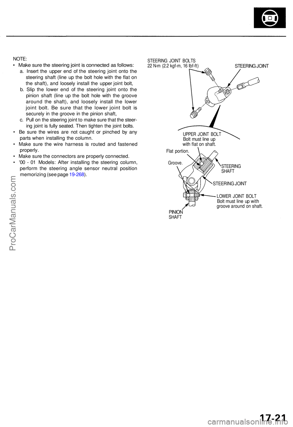
• Mak e sur e th e steerin g join t i s connecte d a s follows :
a. Inser t th e uppe r en d o f th e steerin g join t ont o th e
steerin g shaf t (lin e u p th e bol t hol e wit h th e fla t o n
th e shaft) , an d loosel y instal l th e uppe r join t bolt ,
b . Sli p th e lowe r en d o f th e steerin g join t ont o th e
pinio n shaf t (lin e u p th e bol t hol e wit h th e groov e
aroun d th e shaft) , an d loosel y instal l th e lowe r
joint bolt . B e sur e tha t th e lowe r join t bol t i s
securel y i n th e groov e in th e pinio n shaft ,
c . Pul l o n th e steerin g join t t o mak e sur e tha t th e steer -
in g join t i s full y seated . The n tighte n th e join t bolts .
• B e sur e th e wire s ar e no t caugh t o r pinche d b y an y
part s whe n installin g th e column .
• Mak e sur e th e wir e harnes s i s route d an d fastene d
properly .
• Mak e sur e th e connector s ar e properl y connected .
• '0 0 - 0 1 Models : Afte r installin g th e steerin g column ,
perfor m th e steerin g angl e senso r neutra l positio n
memorizin g (se e pag e 19-268 ).
STEERIN G JOIN T BOLT S22 N- m (2. 2 kgf-m , 1 6 Ibf-ft )STEERIN G JOIN T
UPPE R JOIN T BOL TBolt mus t lin e u pwit h fla t o n shaft .
Flat portion .
Groove.
STEERING
SHAF T
STEERIN G JOIN T
LOWE R JOIN T BOL TBolt mus t lin e u p wit hgroov e aroun d o n shaft .
PINIONSHAF T
ProCarManuals.com
Page 989 of 1954
Power Steering Hoses, Lines
Fluid Leakage Inspection
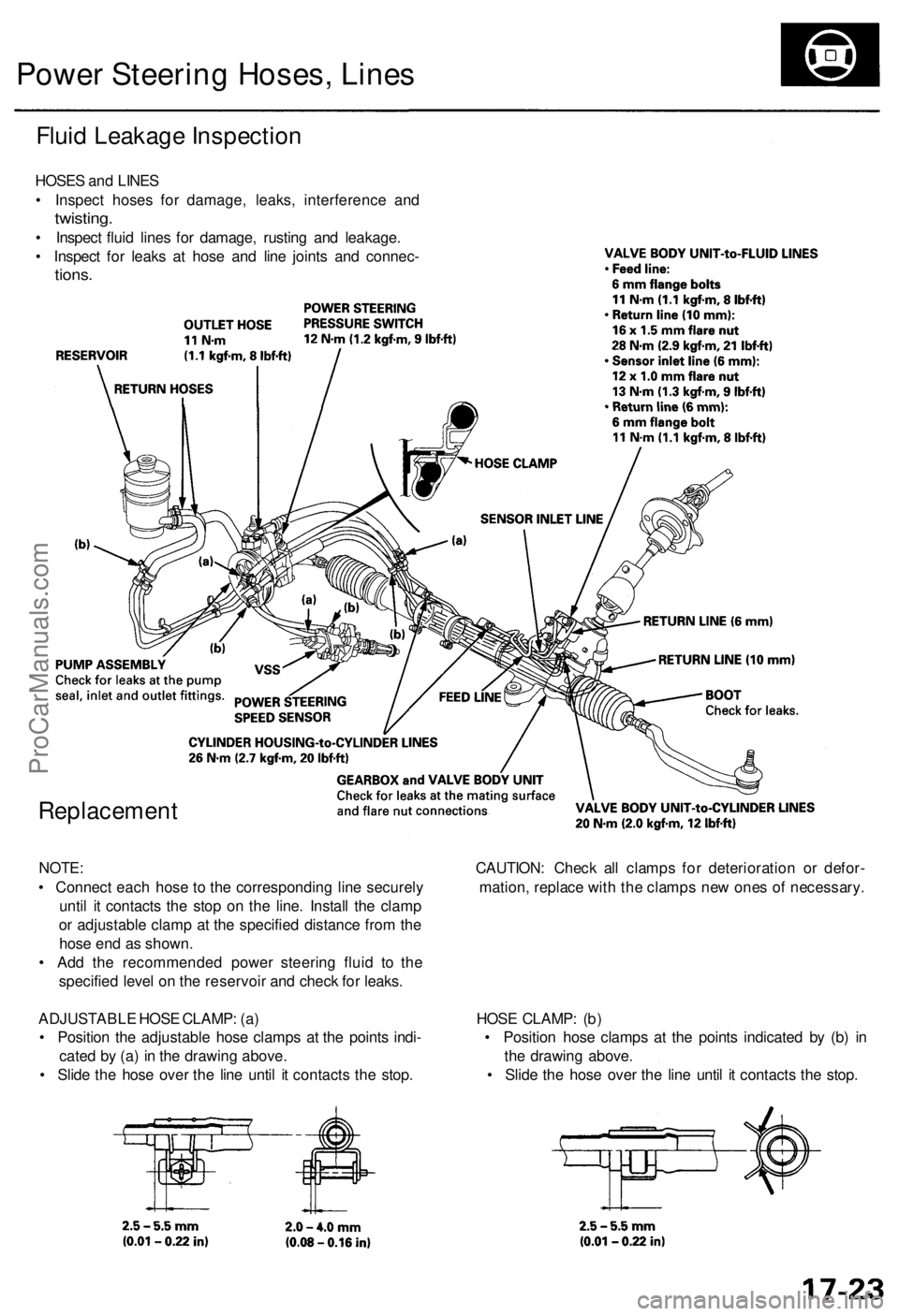
HOSES and LINES
• Inspect hoses for damage, leaks, interference and
twisting.
• Inspect fluid lines for damage, rusting and leakage.
• Inspect for leaks at hose and line joints and connec-
tions.
Replacement
NOTE: CAUTION: Check all clamps for deterioration or defor-
• Connect each hose to the corresponding line securely mation, replace with the clamps new ones of necessary.
until it contacts the stop on the line. Install the clamp
or adjustable clamp at the specified distance from the
hose end as shown.
• Add the recommended power steering fluid to the
specified level on the reservoir and check for leaks.
ADJUSTABLE HOSE CLAMP: (a) HOSE CLAMP: (b)
• Position the adjustable hose clamps at the points indi- • Position hose clamps at the points indicated by (b) in
cated by (a) in the drawing above. the drawing above.
• Slide the hose over the line until it contacts the stop. • Slide the hose over the line until it contacts the stop.ProCarManuals.com
Page 990 of 1954
Power Steerin g Pum p
Removal/Installatio n
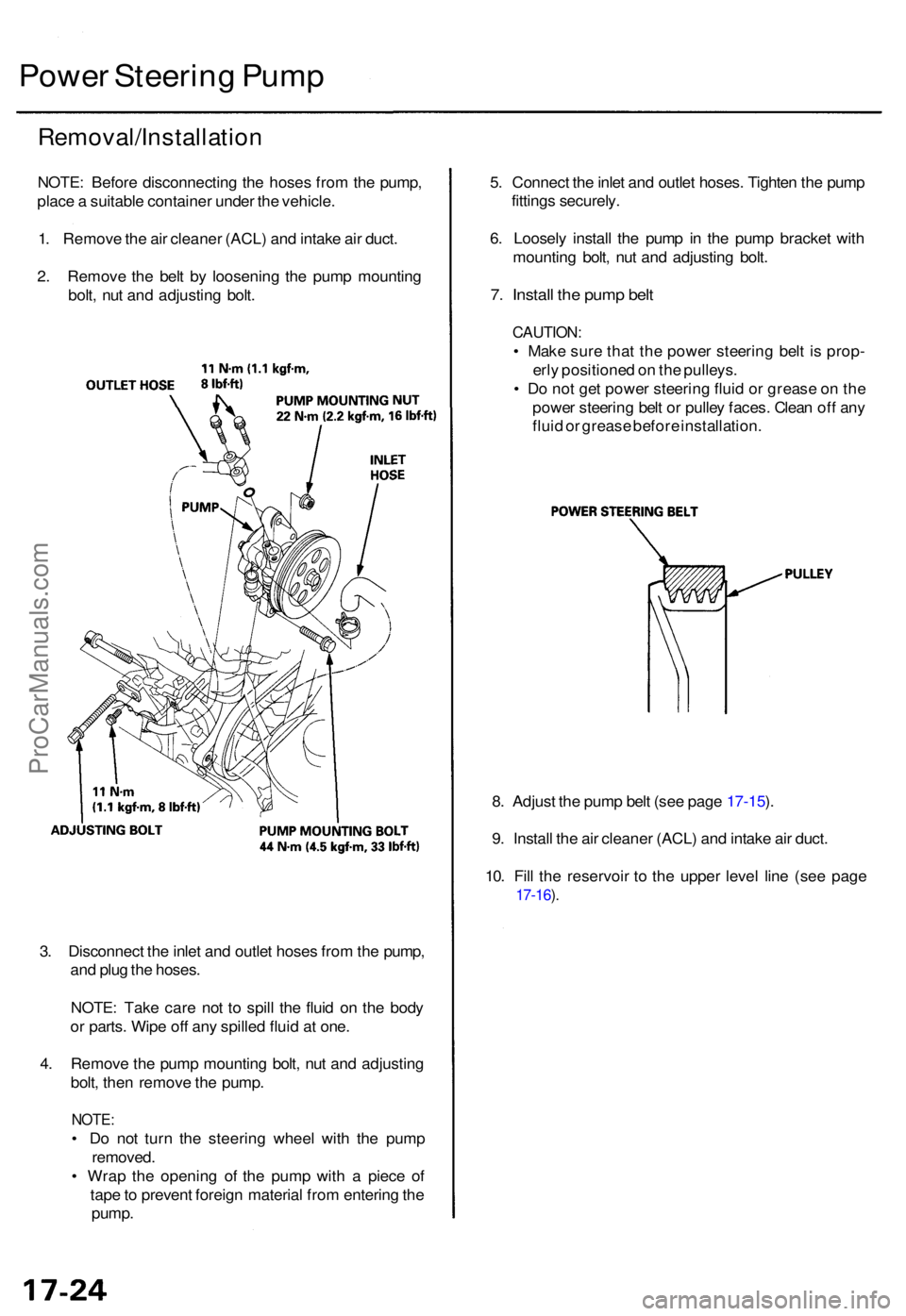
NOTE: Befor e disconnectin g th e hose s fro m th e pump ,
plac e a suitabl e containe r unde r th e vehicle .
1 . Remov e th e ai r cleane r (ACL ) an d intak e ai r duct .
2 . Remov e th e bel t b y loosenin g th e pum p mountin g
bolt , nu t an d adjustin g bolt . 5
. Connec t th e inle t an d outle t hoses . Tighte n th e pum p
fitting s securely .
6 . Loosel y instal l th e pum p i n th e pum p bracke t wit h
mountin g bolt , nu t an d adjustin g bolt .
7. Instal l th e pum p bel t
CAUTION :
• Mak e sur e tha t th e powe r steerin g bel t i s prop -
erl y positione d o n th e pulleys .
• D o no t ge t powe r steerin g flui d o r greas e o n th e
powe r steerin g bel t o r pulle y faces . Clea n of f an y
flui d o r greas e befor e installation .
8 . Adjus t th e pum p bel t (se e pag e 17-15 ).
9 . Instal l th e ai r cleane r (ACL ) an d intak e ai r duct .
10 . Fil l th e reservoi r t o th e uppe r leve l lin e (se e pag e
17-16 ).
3 . Disconnec t th e inle t an d outle t hose s fro m th e pump ,
an d plu g th e hoses .
NOTE : Tak e car e no t t o spil l th e flui d o n th e bod y
o r parts . Wip e of f an y spille d flui d a t one .
4 . Remov e th e pum p mountin g bolt , nu t an d adjustin g
bolt , the n remov e th e pump .
NOTE:
• D o no t tur n th e steerin g whee l wit h th e pum p
removed .
• Wra p th e openin g o f th e pum p wit h a piec e o f
tap e to preven t foreig n materia l fro m enterin g th e
pump .
ProCarManuals.com
Page 1004 of 1954
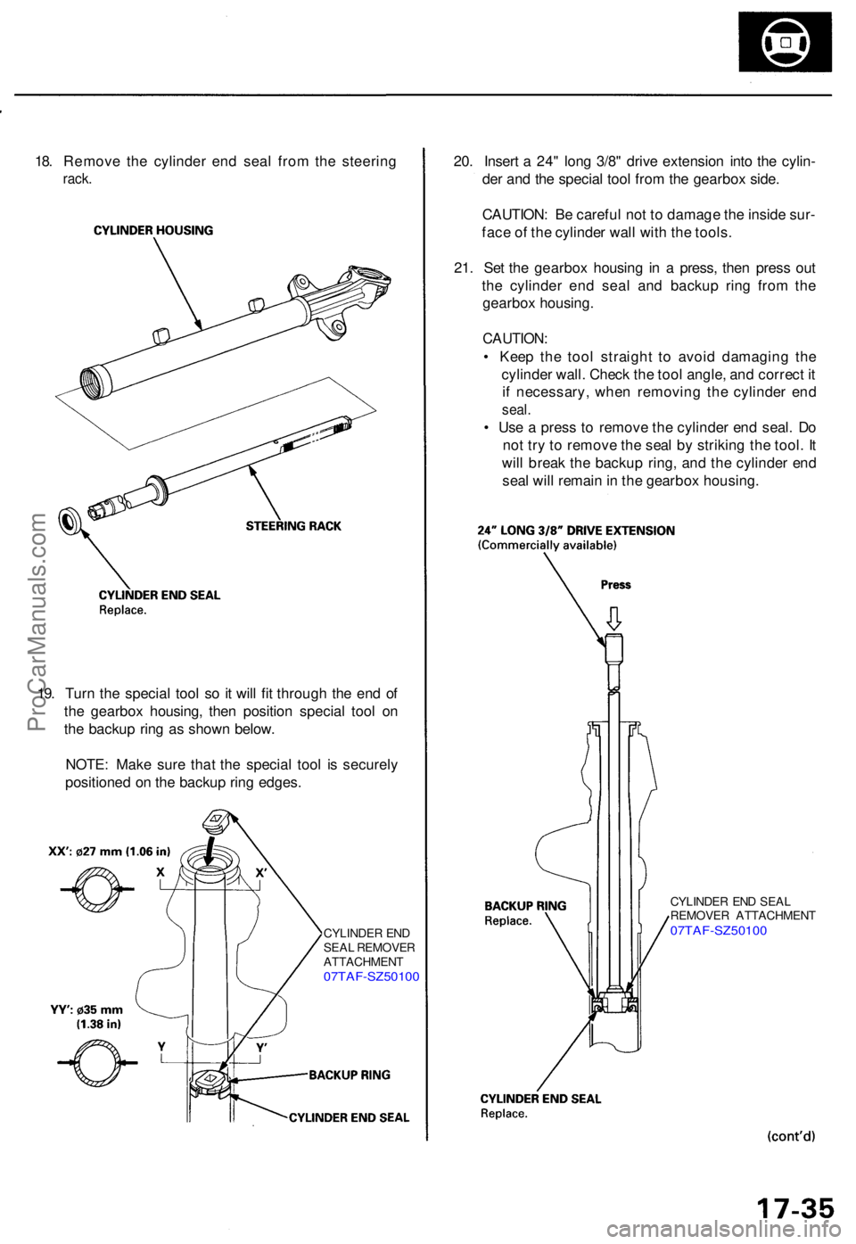
18. Remov e th e cylinde r en d sea l fro m th e steerin g
rack.
20. Inser t a 24 " lon g 3/8 " driv e extensio n int o th e cylin -
de r an d th e specia l too l fro m th e gearbo x side .
CAUTION : B e carefu l no t t o damag e th e insid e sur -
fac e o f th e cylinde r wal l wit h th e tools .
21 . Se t th e gearbo x housin g i n a press , the n pres s ou t
th e cylinde r en d sea l an d backu p rin g fro m th e
gearbo x housing .
CAUTION :
• Kee p th e too l straigh t t o avoi d damagin g th e
cylinde r wall . Chec k th e too l angle , an d correc t i t
i f necessary , whe n removin g th e cylinde r en d
seal .
• Us e a pres s t o remov e th e cylinde r en d seal . D o
no t tr y t o remov e th e sea l b y strikin g th e tool . I t
wil l brea k th e backu p ring , an d th e cylinde r en d
sea l wil l remai n in th e gearbo x housing .
19 . Tur n th e specia l too l s o i t wil l fi t throug h th e en d o f
th e gearbo x housing , the n positio n specia l too l o n
th e backu p rin g a s show n below .
NOTE : Mak e sur e tha t th e specia l too l i s securel y
positione d o n th e backu p rin g edges .
CYLINDE R EN D
SEA L REMOVE R
ATTACHMEN T
07TAF-SZ5010 0
CYLINDER EN D SEA L
REMOVE R ATTACHMEN T
07TAF-SZ5010 0
ProCarManuals.com
Page 1012 of 1954
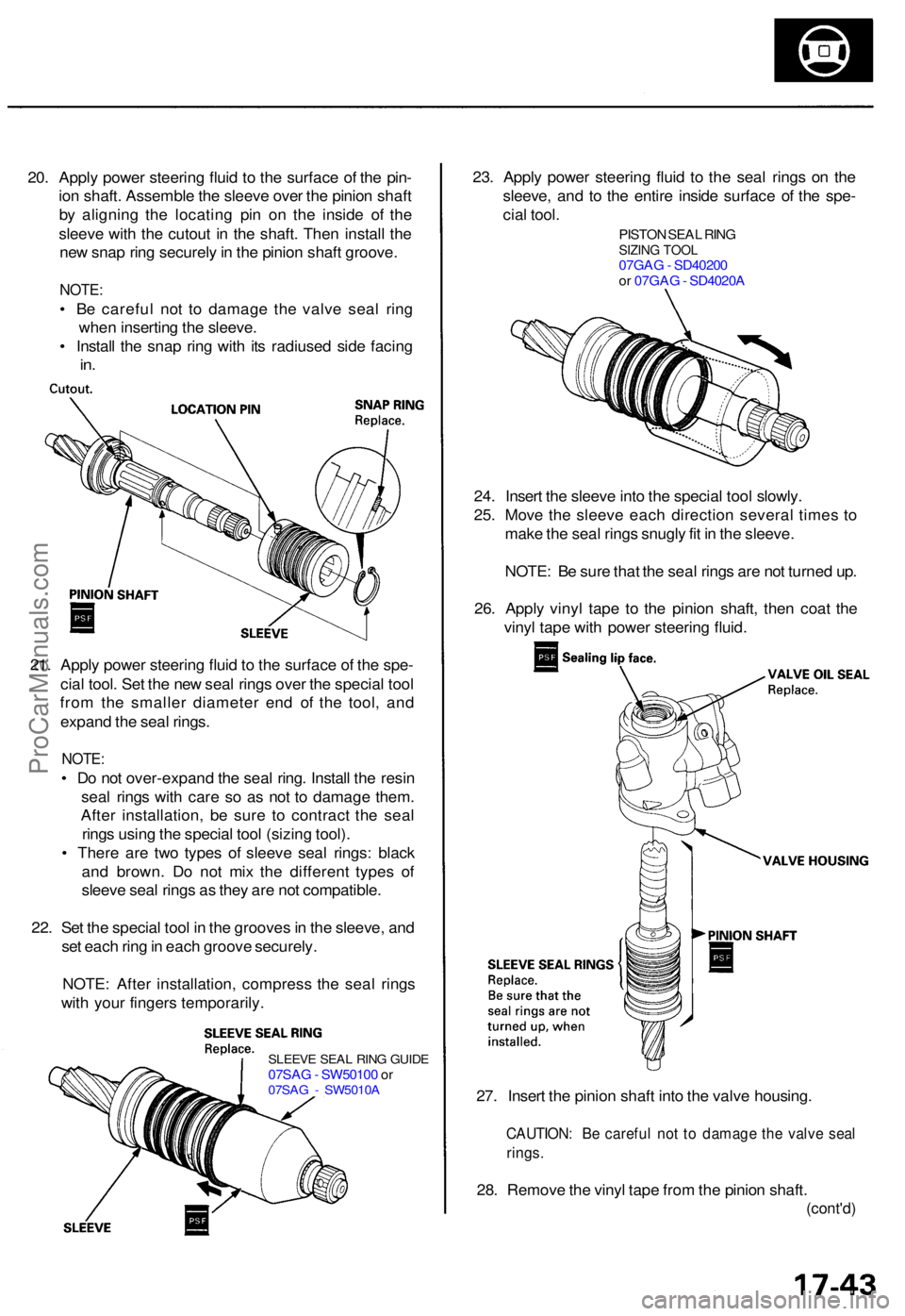
SLEEVE SEA L RIN G GUID E07SAG - SW5010 0 o r07SA G - SW5010 A27. Inser t th e pinio n shaf t int o th e valv e housing .
CAUTION : B e carefu l no t t o damag e th e valv e sea l
rings .
28. Remov e th e viny l tap e fro m th e pinio n shaft .
(cont'd )
20. Appl y powe r steerin g flui d t o th e surfac e o f th e pin -
io n shaft . Assembl e th e sleev e ove r th e pinio n shaf t
b y alignin g th e locatin g pi n o n th e insid e of the
sleev e wit h th e cutou t i n th e shaft . The n instal l th e
ne w sna p rin g securel y in th e pinio n shaf t groove .
NOTE:
• B e carefu l no t t o damag e th e valv e sea l rin g
whe n insertin g th e sleeve .
• Instal l th e sna p rin g wit h it s radiuse d sid e facin g
in.
23 . Appl y powe r steerin g flui d t o th e sea l ring s o n th e
sleeve , an d t o th e entir e insid e surfac e o f th e spe -
cia l tool .
PISTO N SEA L RIN GSIZIN G TOO L07GA G - SD4020 0
o r 07GA G - SD4020 A
24. Inser t th e sleev e int o th e specia l too l slowly .
25 . Mov e th e sleev e eac h directio n severa l time s t o
mak e th e sea l ring s snugl y fi t i n th e sleeve .
NOTE : B e sur e tha t th e sea l ring s ar e no t turne d up .
26 . Appl y viny l tap e t o th e pinio n shaft , the n coa t th e
viny l tap e wit h powe r steerin g fluid .
21 . Appl y powe r steerin g flui d to th e surfac e o f th e spe -
cia l tool . Se t th e ne w sea l ring s ove r th e specia l too l
fro m th e smalle r diamete r en d o f th e tool , an d
expan d th e sea l rings .
NOTE :
• D o no t over-expan d th e sea l ring . Instal l th e resi n
sea l ring s wit h car e s o a s no t t o damag e them .
Afte r installation , b e sur e t o contrac t th e sea l
ring s usin g th e specia l too l (sizin g tool) .
• Ther e ar e tw o type s o f sleev e sea l rings : blac k
an d brown . D o no t mi x th e differen t type s of
sleev e sea l ring s a s the y ar e no t compatible .
22 . Se t th e specia l too l i n th e groove s in th e sleeve , an d
se t eac h rin g in eac h groov e securely .
NOTE : Afte r installation , compres s th e sea l ring s
wit h you r finger s temporarily .
ProCarManuals.com
Page 1018 of 1954
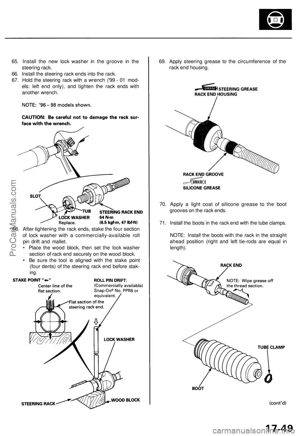
65. Install the new lock washer in the groove in the
steering rack.
66. Install the steering rack ends into the rack.
67. Hold the steering rack with a wrench ('99 - 01 mod-
els: left end only), and tighten the rack ends with
another wrench.
69. Apply steering grease to the circumference of the
rack end housing.
70. Apply a light coat of silicone grease to the boot
grooves on the rack ends.
71. Install the boots in the rack end with the tube clamps.
NOTE: Install the boots with the rack in the straight
ahead position (right and left tie-rods are equal in
length).
68. After tightening the rack ends, stake the four section
of lock washer with a commercially-available roll
pin drift and mallet.
• Place the wood block, then set the lock washer
section of rack end securely on the wood block.
• Be sure the tool is aligned with the stake point
(four dents) of the steering rack end before stak-
ing.ProCarManuals.com
Page 1021 of 1954
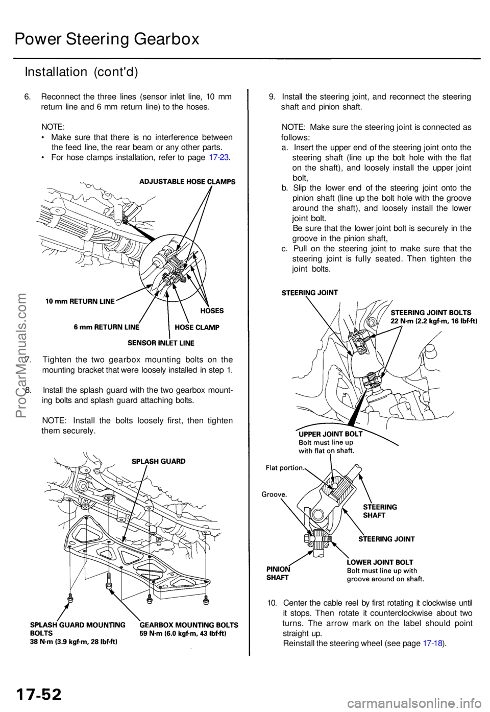
Installation (cont'd )
6. Reconnec t th e thre e line s (senso r inle t line , 1 0 m m
retur n lin e an d 6 m m retur n line ) t o th e hoses .
NOTE:
• Mak e sur e tha t ther e i s n o interferenc e betwee n
th e fee d line , th e rea r bea m o r an y othe r parts .
• Fo r hos e clamp s installation , refe r t o pag e 17-23 . 9
. Instal l th e steerin g joint , an d reconnec t th e steerin g
shaf t an d pinio n shaft .
NOTE : Mak e sur e th e steerin g join t i s connecte d a sfollows :
a. Inser t th e uppe r en d o f th e steerin g join t ont o th e
steerin g shaf t (lin e u p th e bol t hol e wit h th e fla t
o n th e shaft) , an d loosel y instal l th e uppe r join t
bolt,
b. Sli p th e lowe r en d o f th e steerin g join t ont o th e
pinio n shaf t (lin e u p th e bol t hol e wit h th e groov e
aroun d th e shaft) , an d loosel y instal l th e lowe r
joint bolt .
Be sur e tha t th e lowe r join t bol t i s securel y i n th e
groov e in th e pinio n shaft ,
c . Pul l o n th e steerin g join t t o mak e sur e tha t th e
steerin g join t i s full y seated . The n tighte n th e
join t bolts .
Power Steerin g Gearbo x
7. Tighte n th e tw o gearbo x mountin g bolt s o n th e
mountin g bracke t tha t wer e loosel y installe d in ste p 1 .
8 . Instal l th e splas h guar d wit h th e tw o gearbo x mount -
in g bolt s an d splas h guar d attachin g bolts .
NOTE : Instal l th e bolt s loosel y first , the n tighte n
the m securely .
10. Cente r th e cabl e ree l b y firs t rotatin g it clockwis e unti l
i t stops . The n rotat e i t counterclockwis e abou t tw o
turns . Th e arro w mar k o n th e labe l shoul d poin t
straigh t up .
Reinstal l th e steerin g whee l (se e pag e 17-18 ).
ProCarManuals.com