1996 ACURA RL KA9 ECU
[x] Cancel search: ECUPage 592 of 1954

Fuel Supply System
Description
By monitoring the Long Term Fuel Trim, long term malfunctions in the fuel system will be detected.
If a
malfunction
has
been detected during
two
consecutive
trips,
the MIL
will
come
on and DTC
P0171, P0172,
P0174
and/or P0175 will be stored.
NOTE: If some of the DTCs listed below are stored at the same time as DTC P0171, P0172, P0174 and/or P0175, trou-
bleshoot those DTCs first, then troubleshoot DTC P0171, P0172, P0174 and/or P0175.
P0106*1, P0107, P0108, P1128*2, P1129*2: MAP Sensor
P0135: Right Primary HO2S Heater (Bank 1, Sensor 1)
P0137, P0138: Secondary HO2S (Sensor 2)
P0141: Secondary HO2S Heater (Sensor 2)
P0155: Left Primary HO2S Heater (Bank 2, Sensor 1)
P0401: EGR Flow Insufficient
P1491: EGR Valve Lift Insufficient
P1498: EGR Valve Position Sensor High Voltage
*1: '96 model only
*2: '97 - 01 models
DTC P0172, P0175
System too rich
• Fuel Pump insufficient flow/pressure
• Fuel Feed Line clogged, leaking
• Fuel Pressure Regulator stuck open
• Fuel Filter clogged
• Injector clogged, air inclusion
• Gasoline doesn't meet Owner's Manual spec.
• Primary HO2S (Sensor 1) deteriorated
• MAP Sensor range/performance*1
• EGR System insufficient flow
• Exhaust leak
• Fuel Pressure Regulator clogged, stuck closed
• Fuel Return Pipe clogged
• Injector leaking
• Gasoline doesn't meet Owner's Manual spec.
• Primary HO2S (Sensor 1) deteriorated
• MAP Sensor range/performance*1
• EGR System malfunction (too much flow)
• EVAP Canister Purge Valve leaking, stuck opened
DTCP0171, P0174
System too lean
The scan tool indicates Diagnostic Trouble Code (DTC) P0171: The fuel system is too lean [Right Bank (Bank 1)].
The scan tool indicates Diagnostic Trouble Code (DTC) P0172: The fuel system is too rich [Right Bank (Bank 1)].
The scan tool indicates Diagnostic Trouble Code (DTC) P0174: The fuel system is too lean [Left Bank (Bank 2)].
The scan tool indicates Diagnostic Trouble Code (DTC) P0175: The fuel system is too rich [Left Bank (Bank 2)].
Possible CauseProCarManuals.com
Page 595 of 1954

PGM-FI System
Misfire Detected in One Cylinder
The scan tool indicates Diagnostic Trouble Code (DTC) P1203 or P1303: Cylinder 3 misfire detected.
The scan tool indicates Diagnostic Trouble Code (DTC) P1204 or P1304: Cylinder 4 misfire detected.
The scan tool indicates Diagnostic Trouble Code (DTC) P1205 or P1305: Cylinder 5 misfire detected.
Description
Misfire detection is accomplished by monitoring the voltage of the spark plug with the spark plug voltage sensor which is
built into the ignition coil.
If misfiring strong enough to damage the catalyst is detected, the MIL will blink during the time of its occurrence, and a
misfire DTC will be stored. Then, after the misfire has ceased, the MIL will come on and stay on whenever the ignition
switch is ON (II).
If misfiring that increases emissions is detected during two consecutive driving cycles, the MIL will come on, and a misfire
DTC will be stored.
NOTE: If some of the DTCs listed below are stored at the same time as a misfire DTC, troubleshoot those DTCs first, then
troubleshoot the misfire DTC.
P0106*1, P1128*2, P1129*2: MAP sensor
P0171, P0172, P0174, P0175: Fuel supply system
P0401, P1491, P1498: EGR system
P1316, P1317, P1318, P1319: Spark Plug Voltage Detection System
P0335, P0336, P1336, P1337: CKP sensor
P1381, P1382, P1386, P1387: CYP sensor
*1: '96 model only
*2: '97 - 01 models
Possible Cause
Injector clogging, fuel leakage, air leakage
Injector circuit open or shorted
Injector resistor malfunction
Spark plug carbon deposits, fouling, malfunction
Ignition coil malfunction
ICM malfunction
Compression low
or
The scan tool indicates Diagnostic Trouble Code (DTC) P1206 or P1306: Cylinder 6 misfire detected.
or
or
or
The scan tool indicates Diagnostic Trouble Code (DTC) P1201 or P1301: Cylinder 1 misfire detected.
The scan tool indicates Diagnostic Trouble Code (DTC) P1202 or P1302: Cylinder 2 misfire detected.
or
orProCarManuals.com
Page 599 of 1954

PGM-FI Syste m
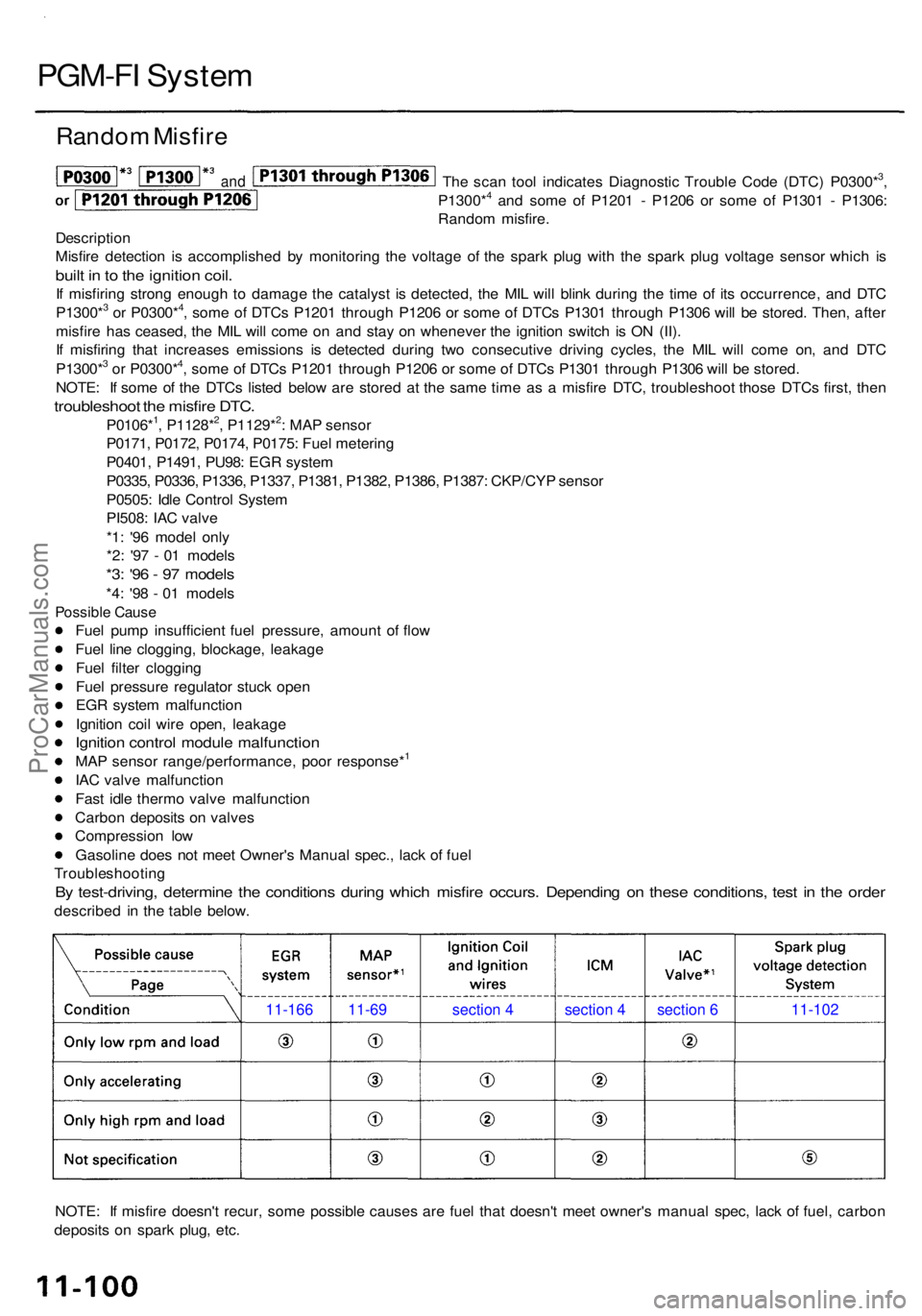
Rando m Misfir e
The sca n too l indicate s Diagnosti c Troubl e Cod e (DTC ) P0300*3,
P1300*4 an d som e o f P120 1 - P120 6 o r som e o f P130 1 - P1306 :
Rando m misfire .
Descriptio n
Misfir e detectio n i s accomplishe d b y monitorin g th e voltag e o f th e spar k plu g wit h th e spar k plu g voltag e senso r whic h i s
buil t i n to th e ignitio n coil .
If misfirin g stron g enoug h t o damag e th e catalys t i s detected , th e MI L wil l blin k durin g th e tim e o f it s occurrence , an d DT C
P1300*3 o r P0300*4, som e o f DTC s P120 1 throug h P120 6 o r som e o f DTC s P130 1 throug h P130 6 wil l b e stored . Then , afte r
misfir e ha s ceased , th e MI L wil l com e o n an d sta y o n wheneve r th e ignitio n switc h i s O N (II) .
I f misfirin g tha t increase s emission s i s detecte d durin g tw o consecutiv e drivin g cycles , th e MI L wil l com e on , an d DT C
P1300*
3 o r P0300*4, som e o f DTC s P120 1 throug h P120 6 o r som e o f DTC s P130 1 throug h P130 6 wil l b e stored .
NOTE : I f som e o f th e DTC s liste d belo w ar e store d a t th e sam e tim e a s a misfir e DTC , troubleshoo t thos e DTC s first , the n
troubleshoo t th e misfir e DTC .
P0106*1, P1128*2, P1129*2: MA P senso r
P0171 , P0172 , P0174 , P0175 : Fue l meterin g
P0401 , P1491 , PU98 : EG R syste m
P0335 , P0336 , P1336 , P1337 , P1381 , P1382 , P1386 , P1387 : CKP/CY P senso r
P0505 : Idl e Contro l Syste m
PI508 : IA C valv e
*1 : '9 6 mode l onl y
*2 : '9 7 - 0 1 model s
*3: '9 6 - 9 7 model s
*4: '9 8 - 0 1 model s
Possibl e Caus e
Fuel pum p insufficien t fue l pressure , amoun t o f flo w
Fue l lin e clogging , blockage , leakag e
Fue l filte r cloggin g
Fue l pressur e regulato r stuc k ope n
EG R syste m malfunctio n
Ignitio n coi l wir e open , leakag e
Ignition contro l modul e malfunction
MA P senso r range/performance , poo r response*1
IA C valv e malfunctio n
Fas t idl e therm o valv e malfunctio n
Carbo n deposit s o n valve s
Compressio n lo w
Gasolin e doe s no t mee t Owner' s Manua l spec. , lac k o f fue l
Troubleshootin g
By test-driving , determin e th e condition s durin g whic h misfir e occurs . Dependin g o n thes e conditions , tes t i n th e orde r
describe d i n th e tabl e below .
NOTE : I f misfir e doesn' t recur , som e possibl e cause s ar e fue l tha t doesn' t mee t owner' s manua l spec , lac k o f fuel , carbo n
deposit s o n spar k plug , etc .
11-166 11-69 section 4 section 4 section 6 11-102
and
ProCarManuals.com
Page 631 of 1954

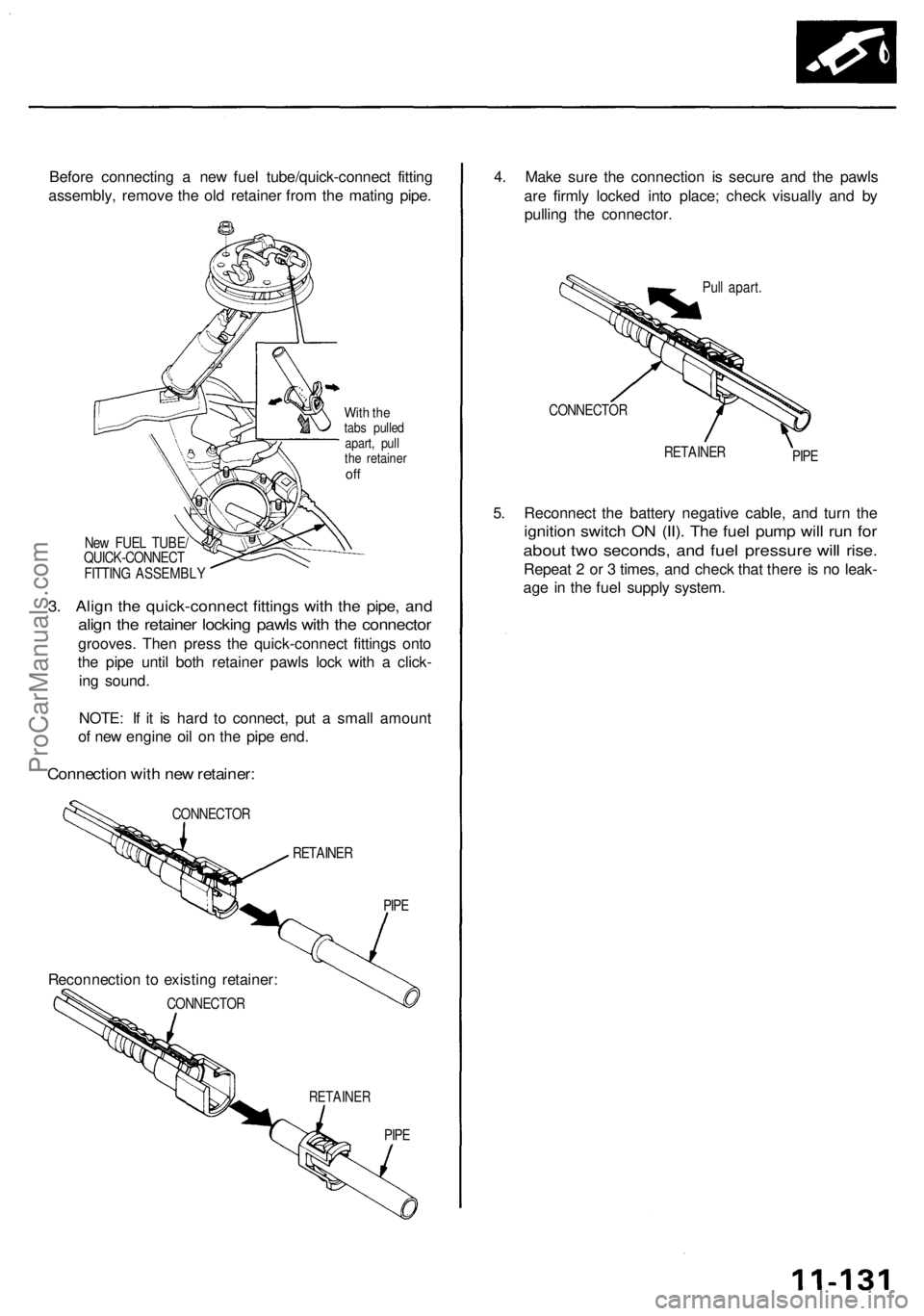
Before connectin g a ne w fue l tube/quick-connec t fittin g
assembly , remov e th e ol d retaine r fro m th e matin g pipe .
With th etab s pulle d
apart , pul l
th e retaine r
off
Ne w FUE L TUBE /
QUICK-CONNEC T
FITTIN G ASSEMBL Y
3. Alig n th e quick-connec t fitting s wit h th e pipe , an d
align th e retaine r lockin g pawl s wit h th e connecto r
grooves. The n pres s th e quick-connec t fitting s ont o
th e pip e unti l bot h retaine r pawl s loc k wit h a click -
in g sound .
NOTE : I f i t i s har d t o connect , pu t a smal l amoun t
o f ne w engin e oi l o n th e pip e end .
Connectio n wit h ne w retainer :
CONNECTO R
RETAINER
RETAINE R
PIPE
4. Mak e sur e th e connectio n i s secur e an d th e pawl s
ar e firml y locke d int o place ; chec k visuall y an d b y
pullin g th e connector .
Pull apart .
CONNECTO R
RETAINERPIPE
5. Reconnec t th e batter y negativ e cable , an d tur n th e
ignitio n switc h O N (II) . Th e fue l pum p wil l ru n fo r
abou t tw o seconds , an d fue l pressur e wil l rise .
Repea t 2 o r 3 times , an d chec k tha t ther e is n o leak -
ag e in th e fue l suppl y system .
CONNECTO R
Reconnectio n to existin g retainer :
PIPE
ProCarManuals.com
Page 656 of 1954

Intake Air System
System Description
The system supplies air for all engine needs. It consists of the intake air pipe. Air Cleaner, intake air duct. Throttle Body,
Idle Air Control (IAC) Valve, idle air control thermal valve, and intake manifold.
A resonator in the intake air pipe provides additional silencing as air is drawn into the system.
IMRC SOLENOID VALVE 2
IMRC
SOLENOID
VALVE 1
IMRC
VACUUM
TANK
From No. 20 ECU
(PCM)
(20 A)
FUSE
(in the under-dash
fuse/relay box)
IMRC
DIAPHRAGM
VALVE 1
VARIOUS
SENSORS
THROTTLE BODY
INTAKE
AIR
DUCT
INTAKE
MANIFOLD
IDLE
ADJUSTING
SCREW
With
TCS
IDLE AIR
CONTROL
THERMAL
VALVE
IAC
VALVE
From PGM-FI
MAIN RELAY
IMRC
DIAPHRAGM
VALVE 2
IMRC
CHECK
VALVE
ENGINE
COOLANTProCarManuals.com
Page 669 of 1954

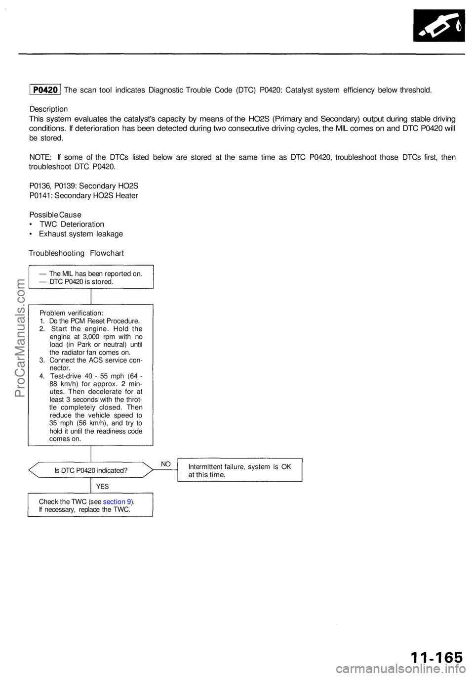
The sca n too l indicate s Diagnosti c Troubl e Cod e (DTC ) P0420 : Catalys t syste m efficienc y belo w threshold .
Descriptio n
This syste m evaluate s th e catalyst' s capacit y b y mean s o f th e HO2 S (Primar y an d Secondary ) outpu t durin g stabl e drivin g
conditions . I f deterioratio n ha s bee n detecte d durin g tw o consecutiv e drivin g cycles , th e MI L come s o n an d DT C P042 0 wil l
be stored .
NOTE : I f som e o f th e DTC s liste d belo w ar e store d a t th e sam e tim e a s DT C P0420 , troubleshoo t thos e DTC s first , the n
troubleshoo t DT C P0420 .
P0136 , P0139 : Secondar y HO2 S
P0141 : Secondar y HO2 S Heate r
Possibl e Caus e
• TW C Deterioratio n
• Exhaus t syste m leakag e
Troubleshootin g Flowchar t
— Th e MI L ha s bee n reporte d on .
— DT C P042 0 is stored .
Proble m verification :
1 . D o th e PC M Rese t Procedure .
2 . Star t th e engine . Hol d th e
engin e a t 3,00 0 rp m wit h n o
loa d (i n Par k o r neutral ) unti l
th e radiato r fa n come s on .
3 . Connec t th e AC S servic e con -
nector .
4 . Test-driv e 4 0 - 5 5 mp h (6 4 -
8 8 km/h ) fo r approx . 2 min -
utes . The n decelerat e fo r a t
leas t 3 second s wit h th e throt -
tl e completel y closed . The n
reduc e th e vehicl e spee d t o
3 5 mp h (5 6 km/h) , an d tr y t o
hol d it unti l th e readines s cod e
come s on .
I s DT C P042 0 indicated ?
YES
Chec k th e TW C (se e sectio n 9 ).
I f necessary , replac e th e TWC . Intermitten
t failure , syste m is O K
at thi s time .
NO
ProCarManuals.com
Page 670 of 1954

Emission Control System
Exhaust Gas Recirculation (EGR) System
Description
The EGR system is designed to reduce oxides of nitrogen emissions (NOx) by recirculating exhaust gas through the EGR
valve and the intake manifold into the combustion chambers. It is composed of the EGR valve, EGR valve vacuum control
valve, EGR valve vacuum control solenoid valve, PCM and various sensors.
The PCM contains memories for ideal EGR valve lifts for varying operating conditions. The EGR valve position sensor
detects the amount of EGR valve lift and sends the information to the PCM. The PCM then compares it with the ideal EGR
valve lift which is determined by signals sent from the other sensors. If there is any difference between the two, the PCM
cuts current to the EGR valve vacuum control solenoid valve to reduce vacuum applied to the EGR valve.
EGR VALVE
POSITION SENSOR
INTAKE MANIFOLD
From No. 20 ECU (PCM)
(20 A) FUSE
(in the under-dash
fuse/relay box)
VARIOUS
SENSORS
EGR VALVE
EGR VALVE
VACUUM
CONTROL
SOLENOID
VALVE
EGR VALVE
VACUUM
CONTROL
VALVEProCarManuals.com
Page 671 of 1954

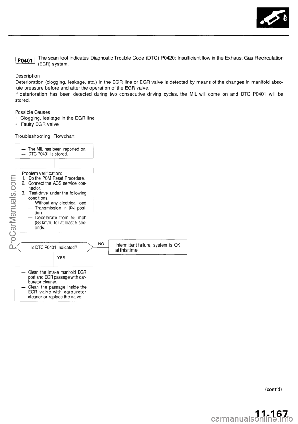
The scan tool indicates Diagnostic Trouble Code (DTC) P0420: Insufficient flow in the Exhaust Gas Recirculation
(EGR)
system.
Description
Deterioration (clogging, leakage, etc.) in the EGR line or EGR valve is detected by means of the changes in manifold abso-
lute pressure before and after the operation of the EGR valve.
If deterioration has been detected during two consecutive driving cycles, the MIL will come on and DTC P0401 will be
stored.
Possible Causes
• Clogging, leakage in the EGR line
• Faulty EGR valve
Troubleshooting Flowchart
Is DTC P0401 indicated?
Intermittent failure, system is OK
at this time.
YES
Clean the intake manifold EGR
port and EGR passage with car-
buretor cleaner.
Clean the passage inside the
EGR valve with carburetor
cleaner or replace the valve.
NO
Problem verification:
1. Do the PCM Reset Procedure.
2. Connect the ACS service con-
nector.
3. Test-drive under the following
conditions.
— Without any electrical load
— Transmission in posi-
tion
— Decelerate from 55 mph
(88 km/h) for at least 5 sec-
onds.
The MIL has been reported on.
DTC P0401 is stored.ProCarManuals.com