Page 1217 of 1954
Troubleshooting
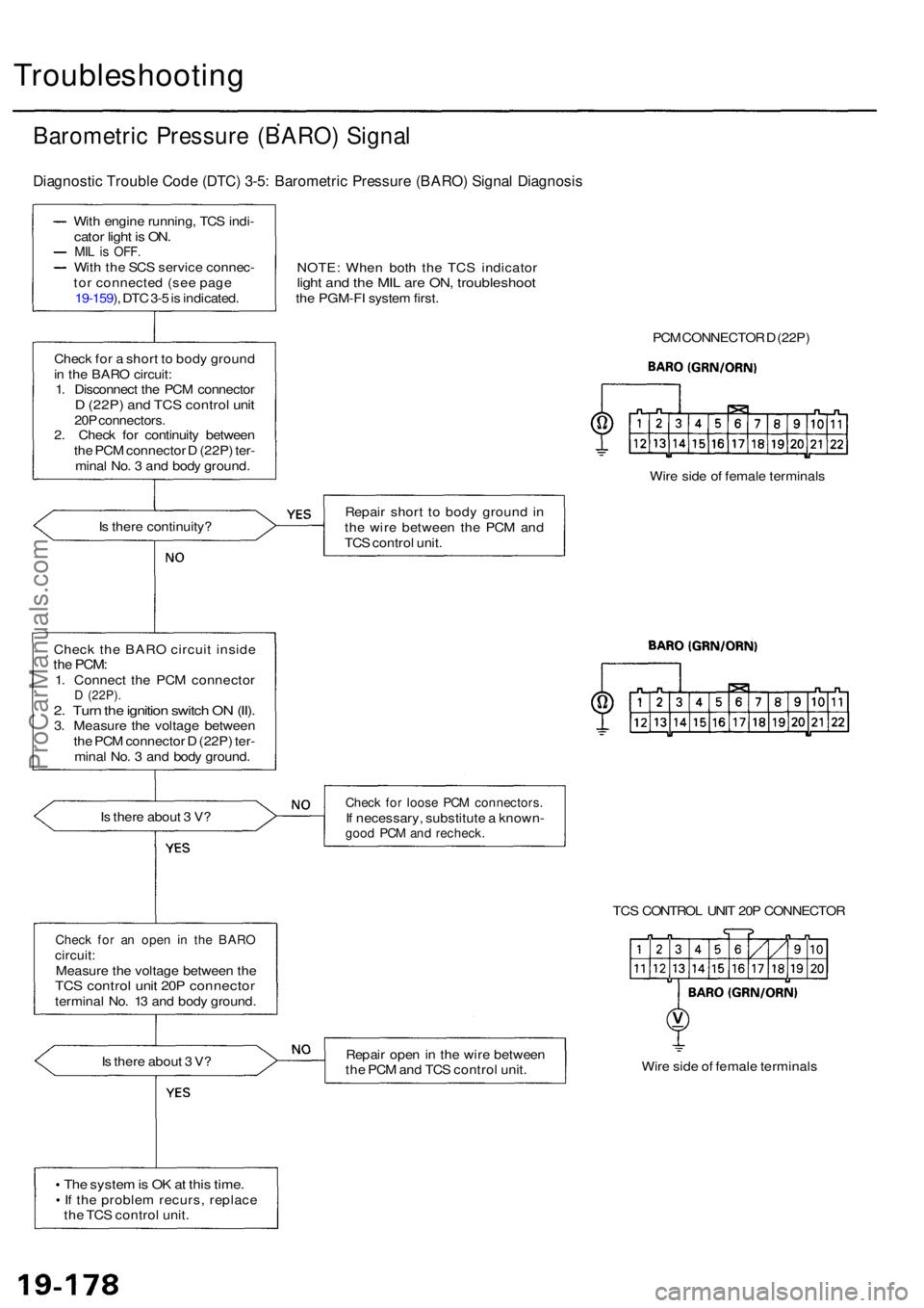
Barometric Pressur e (BARO ) Signa l
Diagnosti c Troubl e Cod e (DTC ) 3-5 : Barometri c Pressur e (BARO ) Signa l Diagnosi s
With engin e running , TC S indi -cato r ligh t i s ON .MIL is OFF .With th e SC S servic e connec -
to r connecte d (se e pag e
19-159 ), DT C 3- 5 is indicated .
Chec k fo r a shor t t o bod y groun d
i n th e BAR O circuit :
1 . Disconnec t th e PC M connecto r
D (22P ) an d TC S contro l uni t20P connectors .2. Chec k fo r continuit y betwee n
th e PC M connecto r D (22P ) ter -
mina l No . 3 an d bod y ground .
I s ther e continuity ?
Chec k th e BAR O circui t insid e
the PCM :1. Connec t th e PC M connecto rD (22P) .2. Tur n th e ignitio n switc h O N (II) .3. Measur e th e voltag e betwee n
th e PC M connecto r D (22P ) ter -
mina l No . 3 an d bod y ground .
I s ther e abou t 3 V ?
Chec k fo r a n ope n i n th e BAR Ocircuit :Measur e th e voltag e betwee n th eTC S contro l uni t 20 P connecto rterminal No . 1 3 an d bod y ground .
I s ther e abou t 3 V ?
Th e syste m is O K at thi s time .If th e proble m recurs , replac e
th e TC S contro l unit . NOTE
: Whe n bot h th e TC S indicato r
light an d th e MI L ar e ON , troubleshoo tthe PGM-F I syste m first .
PCM CONNECTO R D (22P )
Wir e sid e o f femal e terminal s
Repai r shor t t o bod y groun d in
th e wir e betwee n th e PC M an d
TC S contro l unit .
Chec k fo r loos e PC M connectors .If necessary , substitut e a known -good PC M an d recheck .
TCS CONTRO L UNI T 20 P CONNECTO R
Repai r ope n in th e wir e betwee n
th e PC M an d TC S contro l unit . Wir
e sid e o f femal e terminal s
ProCarManuals.com
Page 1218 of 1954
Throttle Positio n Senso r (TPS ) Signa l
Diagnosti c Troubl e Cod e (DTC ) 3-6 : Throttl e Positio n Senso r (TPS ) Signa l Diagnosi s
With engin e running , TC S
indicato r ligh t i s ON .
MIL is OFF .With th e SC S servic e connec -
to r connecte d (se e pag e
19-159 ), DT C 3- 6 is indicated .NOTE
: Whe n bot h th e TC S indicato rlight an d th e MI L ar e ON , trouble -shoot th e PGM-F I syste m first .
TCS CONTRO L UNI T 14 P CONNECTO R
Check fo r a n ope n i n th e TP S cir -cuit :Measur e th e voltag e betwee n th e
TC S contro l uni t 14 P connecto r
termina l No . 1 4 an d bod y ground .
I s th e voltag e a s specified ?
Full y closed : abou t 0. 5 V
Full y open : abou t 4. 5 V Repai
r ope n in th e wir e betwee n
th e PC M an d TC S contro l unit . Wir
e sid e o f femal e terminal s
Th e syste m is O K at thi s time .
I f th e proble m recurs , replac e
th e TC S contro l unit .
ProCarManuals.com
Page 1220 of 1954
From pag e 19-18 0
Check th e TC S contro l valv e sen -sor:1. Remov e th e intak e ai r duc t(see pag e 19-192 ).2 . Tur n th e ignitio n switc h O N (II) .
3 . Connec t th e batter y an d TC S
contro l valv e actuato r (se e
pag e 19-189 ).
4 . Measur e th e voltag e betwee n
th e TC S control unit H P con -
necto r termina l No . 6 an d
bod y ground . TC
S CONTRO L UNI T 14 P CONNECTO R
Wir e sid e o f femal e terminal s
I s th e voltag e a s specified ?
Full y closed : abou t 0. 5 V
Full y open : abou t 4. 5 V
NOTE : Ther e shoul d b e a smoot h
transitio n fro m abou t 4. 5 V an d
0. 5 V as th e TC S contro l valv e is
closed .
Check fo r a n ope n i n th e wir e
betwee n th e TC S contro l uni t
and TC S contro l valv e sensor .If th e wir e is OK , replac e th e TC S
contro l valv e assembl y (fault y
TC S contro l valv e sensor ) an d
recheck .
The syste m is O K at thi s time .
I f th e proble m recurs , replac e
th e TC S contro l unit .
ProCarManuals.com
Page 1222 of 1954
From pag e 19-18 2
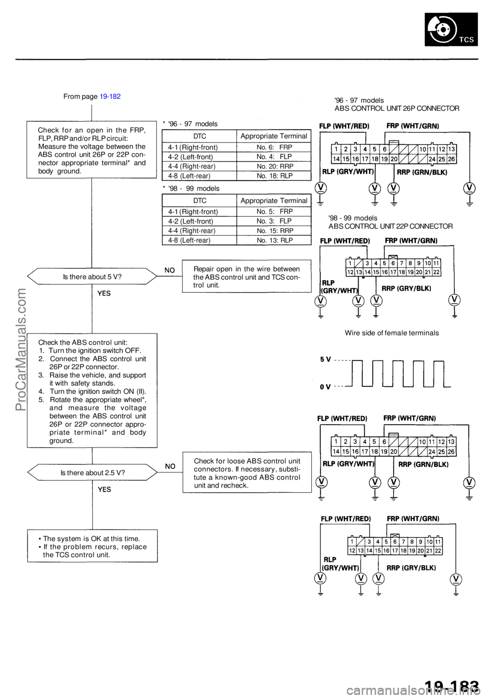
Chec k fo r a n ope n i n th e FRP ,
FLP , RR P and/o r RL P circuit :
Measur e th e voltag e betwee n th e
AB S contro l uni t 26 P o r 22 P con -
necto r appropriat e terminal * an d
bod y ground .
I s ther e abou t 5 V ?
Chec k th e AB S contro l unit :
1. Tur n th e ignitio n switc h OFF .2. Connec t th e AB S contro l uni t
26 P o r 22 P connector .
3 . Rais e th e vehicle , an d suppor t
i t wit h safet y stands .
4 . Tur n th e ignitio n switc h O N (II) .
5 . Rotat e th e appropriat e wheel* ,
an d measur e th e voltag e
betwee n th e AB S contro l uni t
26 P o r 22 P connecto r appro -
priat e terminal * an d bod y
ground .
I s ther e abou t 2. 5 V ? *
'9 6 - 9 7 model s
DTC
4-1 (Right-front )
4- 2 (Left-front )
4-4 (Right-rear )
4-8 (Left-rear )
Appropriat e Termina l
No. 6 : FR P
No. 4 : FL P
No. 20 : RR P
No. 18 : RL P
* '9 8 - 9 9 model s
DTC
4-1 (Right-front )
4- 2 (Left-front )
4-4 (Right-rear )
4-8 (Left-rear )
Appropriat e Termina l
No. 5 : FR P
No. 3 : FL P
No. 15 : RR P
No. 13 : RL P
Repai r ope n in th e wir e betwee n
th e AB S contro l uni t an d TC S con -
tro l unit . '9
6 - 9 7 model s
AB S CONTRO L UNI T 26 P CONNECTO R
'9 8 - 9 9 model s
AB S CONTRO L UNI T 22 P CONNECTO R
Wir e sid e o f femal e terminal s
Chec k fo r loos e AB S contro l uni t
connectors . I f necessary , substi -
tut e a known-goo d AB S contro l
uni t an d recheck .
Th e syste m is O K a t thi s time .
I f th e proble m recurs , replac e
th e TC S contro l unit .
ProCarManuals.com
Page 1223 of 1954
Troubleshooting
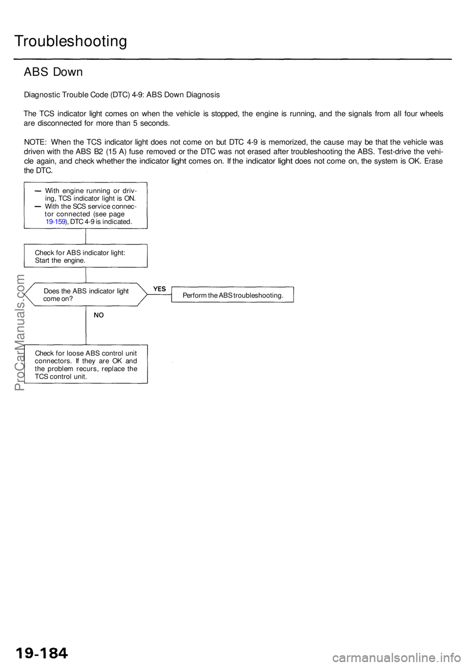
ABS Dow n
Diagnosti c Troubl e Cod e (DTC ) 4-9 : AB S Dow n Diagnosi s
Th e TC S indicato r ligh t come s o n whe n th e vehicl e i s stopped , th e engin e i s running , an d th e signal s fro m al l fou r wheel s
ar e disconnecte d fo r mor e tha n 5 seconds .
NOTE : Whe n th e TC S indicato r ligh t doe s no t com e o n bu t DT C 4- 9 i s memorized , th e caus e ma y b e tha t th e vehicl e wa s
drive n wit h th e AB S B 2 (1 5 A ) fus e remove d o r th e DT C wa s no t erase d afte r troubleshootin g th e ABS . Test-driv e th e vehi -
cle again , and chec k whethe r the indicato r light come s on. I f th e indicato r light doe s not com e on, th e syste m is OK . Eras e
the DTC .
Does th e AB S indicato r ligh t
com e on ? Perfor
m th e AB S troubleshooting .
Chec k fo r loos e AB S contro l uni t
connectors . I f the y ar e O K an d
th e proble m recurs , replac e th e
TC S contro l unit .
Chec
k fo r AB S indicato r light :
Star t th e engine .
Wit
h engin e runnin g o r driv -
ing , TC S indicato r ligh t i s ON .
Wit h th e SC S servic e connec -
to r connecte d (se e pag e
19-159 ), DT C 4- 9 is indicated .
ProCarManuals.com
Page 1224 of 1954
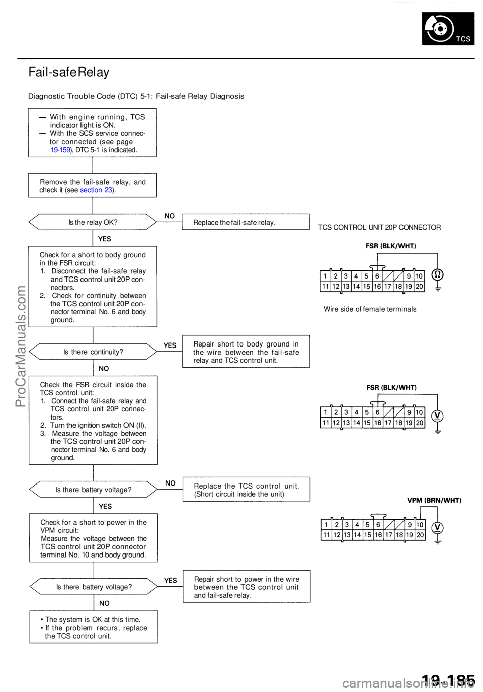
Fail-safe Rela y
Diagnosti c Troubl e Cod e (DTC ) 5-1 : Fail-saf e Rela y Diagnosi s
With engin e running , TC S
indicato r ligh t i s ON .
With th e SC S servic e connec -
to r connecte d (se e pag e
19-159 ), DT C 5- 1 is indicated .
Remov e th e fail-saf e relay , an d
chec k it (se e sectio n 23 ).
I s th e rela y OK ?
Chec k fo r a shor t t o bod y groun d
i n th e FS R circuit :
1 . Disconnec t th e fail-saf e rela y
and TC S control unit 20 P con -nectors .
2 . Chec k fo r continuit y betwee n
the TC S contro l uni t 20 P con -necto r termina l No . 6 an d bod yground .
Is ther e continuity ?
Chec k th e FS R circui t insid e th e
TC S contro l unit :
1 . Connec t th e fail-saf e rela y an d
TC S contro l uni t 20 P connec -
tors .
2. Tur n th e ignitio n switc h O N (II) .3. Measur e th e voltag e betwee nthe TC S contro l uni t 20 P con -necto r termina l No . 6 an d bod yground .
Is ther e batter y voltage ?
Chec k fo r a shor t t o powe r i n th e
VP M circuit :
Measur e th e voltag e betwee n th e
TC S contro l uni t 20 P connecto rterminal No . 1 0 an d bod y ground .
Is ther e batter y voltage ?
Th e syste m is O K a t thi s time .
I f th e proble m recurs , replac e
th e TC S contro l unit . Replac
e th e fail-saf e relay .
TCS CONTRO L UNI T 20 P CONNECTO R
Wir e sid e o f femal e terminal s
Repai r shor t t o bod y groun d i n
th e wir e betwee n th e fail-saf e
rela y an d TC S contro l unit .
Replac e th e TC S contro l unit .
(Shor t circui t insid e th e unit )
Repai r shor t t o powe r i n th e wir ebetwee n th e TC S contro l uni tand fail-saf e relay .
ProCarManuals.com
Page 1234 of 1954
Component Locations
SERVICE CHECK CONNECTOR (2P)
RIGHT-REAR WHEEL SENSOR
VSA CONVERTER UNIT
VSA MODULATOR
CONTROL UNIT
TCS CONTROL
VALVE SENSOR
RIGHT-FRONT
WHEEL SENSOR
PRECHARGE
PUMP MOTOR
STEERING
ANGLE SENSOR
YAW RATE/LATERAL
ACCELERATION SENSOR
TCS CONTROL VALVE
ACTUATOR
UNDER-HOOD
RELAY BOX C
UNDER-HOOD
FUSE/RELAY BOX
VSA OFF SWITCH
UNDER-DASH FUSE/RELAY BOX
LEFT-FRONT WHEEL SENSOR
LEFT-REAR
WHEEL SENSOR
GAUGE ASSEMBLY
ABS INDICATOR
VSA SYSTEM INDICATOR
UNDER-HOOD FUSE/RELAY BOX
STOP/HORN
(20 A) FUSE
BRAKE SYSTEM INDICATOR
VSA ACTIVATION INDICATOR
UNDER-DASH FUSE/RELAY BOX
TCS
(15 A) FUSE
VSA
(20 A) FUSE
METER
(15 A) FUSE
ECU
(20 A) FUSE
METER
(7.5 A) FUSE
BATTERY
(120 A) FUSE
VSA MOTOR (40 A) FUSE
IG SW (50 A) FUSE
UNDER-HOOD RELAY BOX C
FAIL-SAFE RELAY
GAUGE RELAY
PCM
R/C MIRROR
(7.5 A) FUSEProCarManuals.com
Page 1271 of 1954
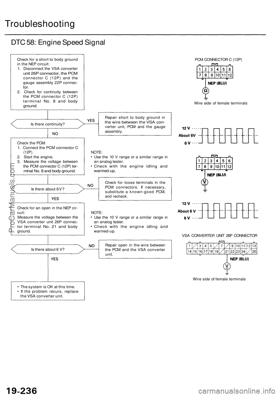
Troubleshooting
DTC 58: Engine Speed Signal
Check for a short to body ground
in the NEP circuit:
1. Disconnect the VSA converter
unit 26P connector, the PCM
connector C (12P) and the
gauge assembly 22P connec-
tor.
2. Check for continuity between
the PCM connector C (12P)
terminal No. 8 and body
ground.
Is there continuity?
Check the PCM:
1. Connect the PCM connector C
(12P).
2. Start the engine.
3. Measure the voltage between
the PCM connector C (12P) ter-
minal No. 8 and body ground.
Is there about 6V?
Check for an open in the NEP cir-
cuit:
Measure the voltage between the
VSA converter unit 26P connec-
tor terminal No. 21 and body
ground.
Is there about 6 V?
The system is OK at this time.
If the problem recurs, replace
the VSA converter unit.
PCM CONNECTOR C (12P)
Wire side of female terminals
Repair short to body ground in
the wire between the VSA con-
verter unit, PCM and the gauge
assembly.
NOTE:
Use the 10 V range or a similar range in
an analog tester.
Check with the engine idling and
warmed-up.
Check for loose terminals in the
PCM connectors. If necessary,
substitute a known-good PCM,
and recheck.
NOTE:
Use the 10 V range or a similar range in
an analog tester.
Check with the engine idling and
warmed-up.
VSA CONVERTER UNIT 26P CONNECTOR
Repair open in the wire between
the PCM and the VSA converter
unit.
Wire side of female terminalsProCarManuals.com