Page 1407 of 1954
Opener an d Latc h
Remova l
NOTE: Tak e car e no t t o ben d th e opene r cables .
Hood releas e handle :
NOTE: Remov e th e dashboar d lowe r cove r (se e pag e
20-49 ).
6 x 1. 0 m m9.8 N- m(1.0 kgf-m ,
7. 2 Ibf-ft ) HOO
D OPENE RCABLE(see pag e 20-87 )
HOODRELEAS EHANDLE
Installatio n i s th e revers e o f th e remova l procedure .
NOTE:
Make sur e th e opene r cabl e i s connecte d properly .
Mak e sur e th e hoo d open s properl y an d lock s
securely .
Hood latch :
: Bol t locations , 3
COVE R
HOOD OPENE RCABLE
Detach th e clip .
HOO D LATC H
SWITC H
CONNECTO R
Installation i s th e revers e o f th e remova l procedure .
NOTE:
Make sur e th e opene r cabl e i s connecte d properly .
Mak e sur e th e hoo d open s properl y an d lock s
securely .
Grease eac h locatio n o f th e hoo d latc h indicate d
by th e arrows .
HOOD LATC H
Bolt locations , 2HOO D LATC H
6 x 1. 0 m m9.8 N- m(1.0 kgf-m ,
7. 2 Ibf-ft )
ProCarManuals.com
Page 1408 of 1954
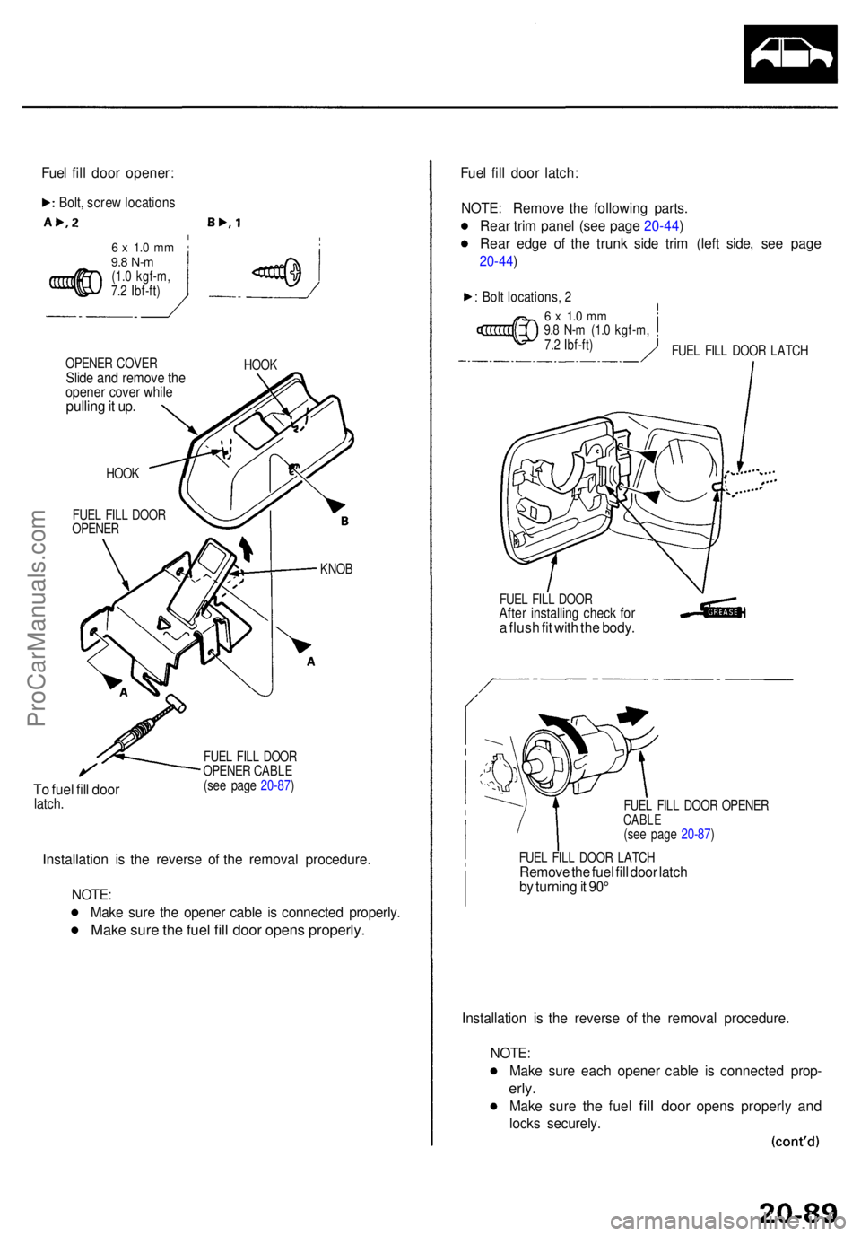
6 x 1. 0 m m9.8 N- m(1.0 kgf-m ,
7. 2 Ibf-ft )
OPENE R COVE R
Slide an d remov e th eopene r cove r whil epullin g it up .
HOO K
FUE L FIL L DOO R
OPENE R HOO
K
To fue l fil l doo rlatch .
KNO B
FUE L FIL L DOO R
OPENE R CABL E
(se e pag e 20-87 )
Installatio n i s th e revers e o f th e remova l procedure .
NOTE :
Mak e sur e th e opene r cabl e i s connecte d properly .
Make sur e th e fue l fil l doo r open s properly .
Fuel fil l doo r latch :
NOTE : Remov e th e followin g parts .
Rea r tri m pane l (se e pag e 20-44 )
Rea r edg e o f th e trun k sid e tri m (lef t side , se e pag e
20-44 )
: Bol t locations , 2
6 x 1. 0 m m9.8 N- m (1. 0 kgf-m ,
7. 2 Ibf-ft )
FUE L FIL L DOO R
After installin g chec k fo ra flus h fi t wit h th e body .
FUEL FIL L DOO R OPENE RCABLE(see pag e 20-87 )
FUE L FIL L DOO R LATC H
Remov e th e fue l fil l doo r latc h
b y turnin g it 90 °
Installatio n i s th e revers e o f th e remova l procedure .
NOTE:
Make sur e eac h opene r cabl e i s connecte d prop -
erly.
Mak e sur e the fue l fill doo r open s properl y and
lock s securely .
Fue
l fil l doo r opener :
Bolt, scre w location s
FUEL FIL L DOO R LATC H
ProCarManuals.com
Page 1409 of 1954
Opener an d Latc h
Remova l (cont'd )
Trunk li d latch/Loc k cylinder :
NOTE : Remov e th e trun k li d tri m (se e pag e 20-78 ).
6 x 1.0 mm9.8 N- m (1. 0 kgf-m ,
7. 2 Ibf-ft )
LOC K CYLINDE R
SWITC H CONNECTO R
LOCKCYLINDE R
TRUNK LI DLATC H
CONNECTO R
Installation is th e revers e o f th e remova l procedure .
NOTE:
Greas e th e trun k latch .
Mak e sur e th e trun k li d open s properl y an d lock s
securely .
Make sur e th e connecto r i s connecte d properly .
Bolt location s
6 x 1. 0 m m9.8 N- m (1. 0 kgf-m ,
7. 2 Ibf-ft )
CYLINDE R
ROD
ProCarManuals.com
Page 1475 of 1954
In-car Temperatur e Senso r
Replacemen t
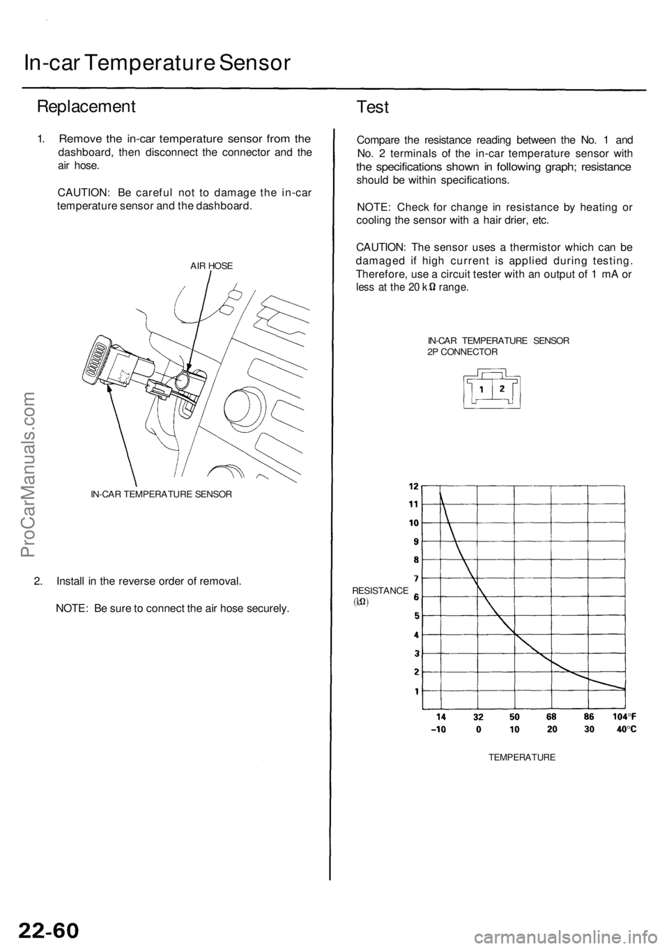
1. Remov e th e in-ca r temperatur e senso r fro m th e
dashboard , the n disconnec t th e connecto r an d th e
ai r hose .
CAUTION : B e carefu l no t t o damag e th e in-ca r
temperatur e senso r an d th e dashboard .
AIR HOS E
IN-CA R TEMPERATUR E SENSO R
2. Instal l i n th e revers e orde r o f removal .
NOTE : B e sur e to connec t th e ai r hos e securely .
Test
Compar e th e resistanc e readin g betwee n th e No . 1 an d
No . 2 terminal s o f th e in-ca r temperatur e senso r wit h
the specification s show n i n followin g graph ; resistanc e
should b e withi n specifications .
NOTE : Chec k fo r chang e i n resistanc e b y heatin g o r
coolin g th e senso r wit h a hai r drier , etc .
CAUTION : Th e senso r use s a thermisto r whic h ca n b e
damage d i f hig h curren t i s applie d durin g testing .
Therefore , us e a circui t teste r wit h a n outpu t o f 1 m A o r
les s a t th e 2 0 k range .
IN-CAR TEMPERATUR E SENSO R
2 P CONNECTO R
RESISTANC E
(k )
TEMPERATUR E
ProCarManuals.com
Page 1485 of 1954
Heater Uni t
Replacemen t (cont'd )
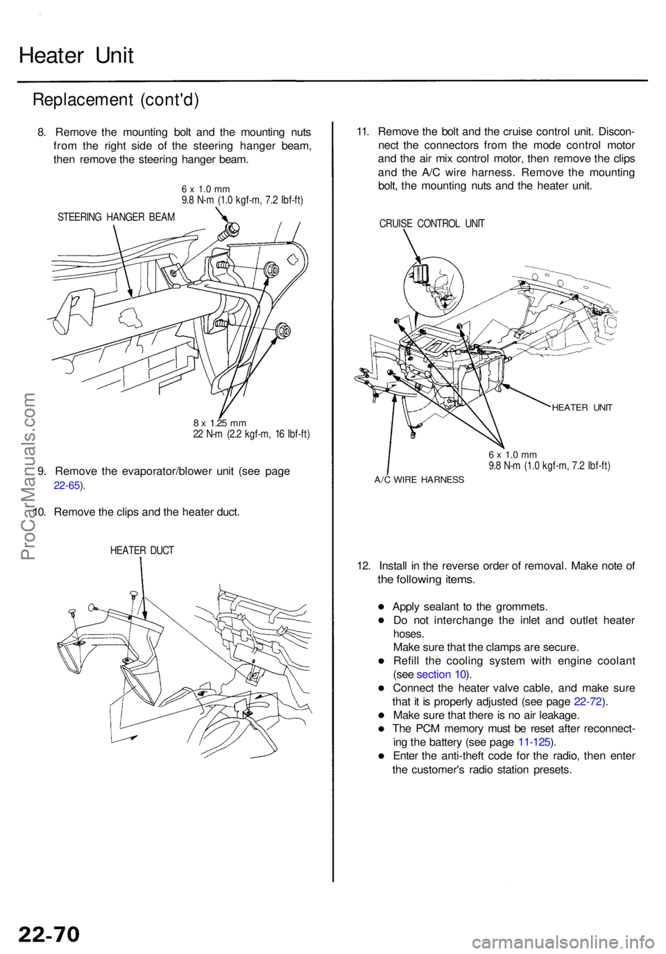
8. Remov e th e mountin g bol t an d th e mountin g nut s
fro m th e righ t sid e o f th e steerin g hange r beam ,
the n remov e th e steerin g hange r beam .
6 x 1. 0 m m9.8 N- m (1. 0 kgf-m , 7. 2 Ibf-ft )
STEERIN G HANGE R BEA M
8 x 1.2 5 mm22 N- m (2. 2 kgf-m , 1 6 Ibf-ft )
9. Remov e th e evaporator/blowe r uni t (se e pag e
22-65 ).
10. Remov e th e clip s an d th e heate r duct .
HEATE R DUC T
11. Remov e th e bol t an d th e cruis e contro l unit . Discon -
nec t th e connector s fro m th e mod e contro l moto r
an d th e ai r mi x contro l motor , the n remov e th e clip s
an d th e A/ C wir e harness . Remov e th e mountin g
bolt , th e mountin g nut s an d th e heate r unit .
CRUIS E CONTRO L UNI T
HEATE R UNI T
6 x 1. 0 m m9.8 N- m (1. 0 kgf-m , 7. 2 Ibf-ft )
A/C WIR E HARNES S
12. Instal l i n th e revers e orde r o f removal . Mak e not e o f
the followin g items .
Apply sealan t t o th e grommets .
D o no t interchang e th e inle t an d outle t heate r
hoses.
Make sur e tha t th e clamp s ar e secure .
Refil l th e coolin g syste m wit h engin e coolan t
(se e sectio n 10 ).
Connec t th e heate r valv e cable , an d mak e sur e
tha t i t i s properl y adjuste d (se e pag e 22-72 ).
Mak e sur e tha t ther e is n o ai r leakage .
Th e PC M memor y mus t b e rese t afte r reconnect -
in g th e batter y (se e pag e 11-125 ).
Ente r th e anti-thef t cod e fo r th e radio , the n ente r
th e customer' s radi o statio n presets .
ProCarManuals.com
Page 1503 of 1954
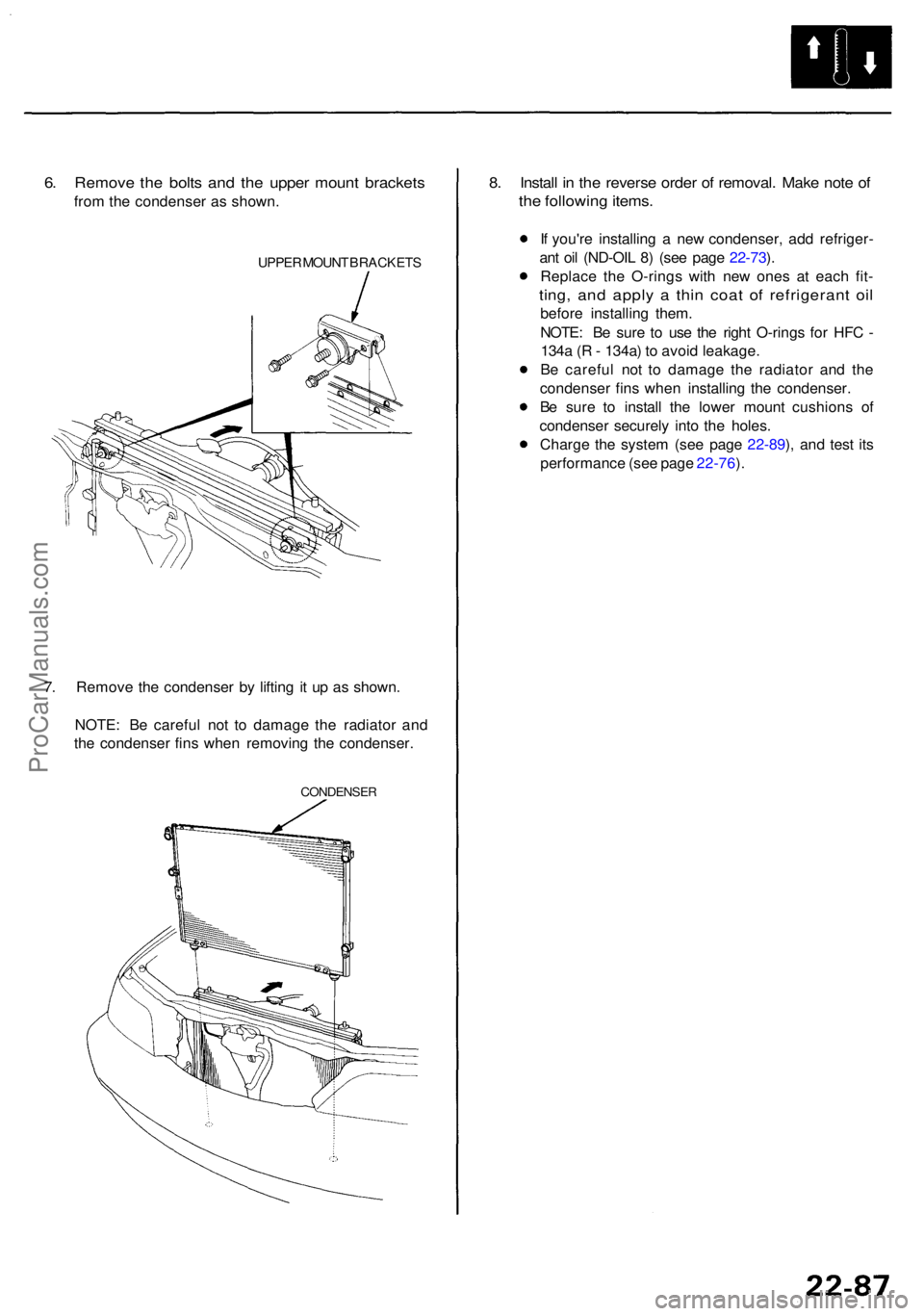
6. Remov e th e bolt s an d th e uppe r moun t bracket s
from th e condense r a s shown .
UPPER MOUN T BRACKET S
7. Remov e th e condense r b y liftin g i t u p a s shown .
NOTE : B e carefu l no t t o damag e th e radiato r an d
th e condense r fin s whe n removin g th e condenser.
CONDENSE R
8. Instal l i n th e revers e orde r o f removal . Mak e not e o f
th e followin g items .
If you'r e installin g a ne w condenser , ad d refriger -
an t oi l (ND-OI L 8 ) (se e pag e 22-73 ).
Replac e th e O-ring s wit h ne w one s a t eac h fit -
ting , an d appl y a thi n coa t o f refrigeran t oi l
befor e installin g them .
NOTE : B e sur e t o us e th e righ t O-ring s fo r HF C -
134 a ( R - 134a ) t o avoi d leakage .
B e carefu l no t t o damag e th e radiato r an d th e
condense r fin s whe n installin g th e condenser .
B e sur e t o instal l th e lowe r moun t cushion s o f
condense r securel y int o th e holes .
Charg e th e syste m (se e pag e 22-89 ), an d tes t it s
performanc e (se e pag e 22-76 ).
ProCarManuals.com
Page 1508 of 1954
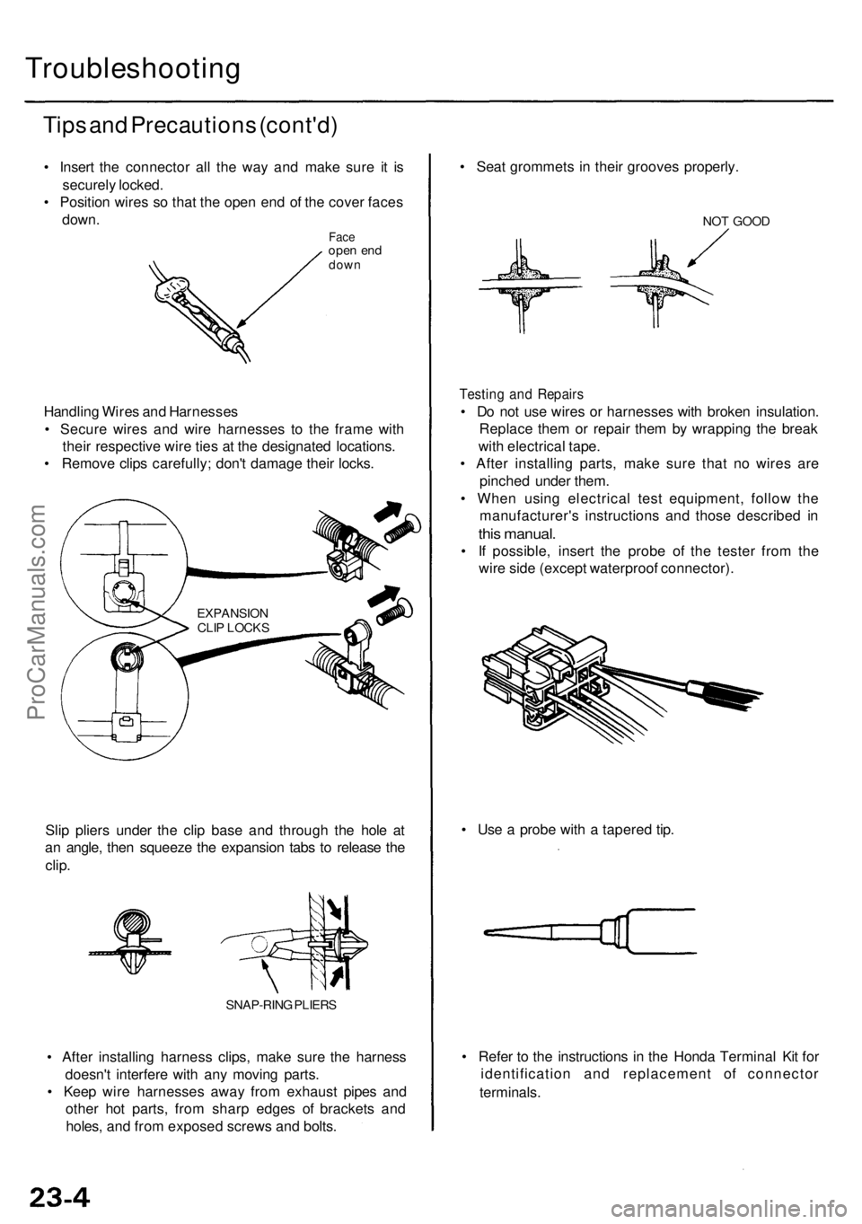
Troubleshooting
Tips an d Precaution s (cont'd )
• Inser t th e connecto r al l th e wa y an d mak e sur e i t i s
securel y locked .
• Positio n wire s s o tha t th e ope n en d o f th e cove r face s
down .
Faceope n en ddow n
Handlin g Wire s an d Harnesse s
• Secur e wire s an d wir e harnesse s t o th e fram e wit h
thei r respectiv e wir e tie s a t th e designate d locations .
• Remov e clip s carefully ; don' t damag e thei r locks .
EXPANSIO NCLIP LOCK S
Slip plier s unde r th e cli p bas e an d throug h th e hol e a t
a n angle , the n squeez e th e expansio n tab s t o releas e th e
clip .
SNAP-RIN G PLIER S
• Afte r installin g harnes s clips , mak e sur e th e harnes s
doesn' t interfer e wit h an y movin g parts .
• Kee p wir e harnesse s awa y fro m exhaus t pipe s an d
othe r ho t parts , fro m shar p edge s o f bracket s an d
holes , an d fro m expose d screw s an d bolts . •
Refe r t o th e instruction s i n th e Hond a Termina l Ki t fo r
identificatio n an d replacemen t o f connecto r
terminals .
•
Us e a prob e wit h a tapere d tip .
•
Sea t grommet s i n thei r groove s properly .
NOT GOO D
Testin g an d Repair s
• D o no t us e wire s o r harnesse s wit h broke n insulation .
Replac e the m o r repai r the m b y wrappin g th e brea k
wit h electrica l tape .
• Afte r installin g parts , mak e sur e tha t n o wire s ar e
pinche d unde r them .
• Whe n usin g electrica l tes t equipment , follo w th e
manufacturer' s instruction s an d thos e describe d i n
thi s manual .
• I f possible , inser t th e prob e of the teste r fro m th e
wir e sid e (excep t waterproo f connector) .
ProCarManuals.com
Page 1509 of 1954
Five-step Troubleshootin g
1. Verif y Th e Complain t
Tur n o n al l th e component s i n th e proble m circui t t o
verif y th e custome r complaint . Not e th e symptoms .
D o no t begi n disassembl y o r testin g unti l yo u hav e
narrowe d dow n th e proble m area .
2. Analyz e Th e Schemati c
Look u p th e schemati c fo r th e proble m circuit .
Determin e ho w th e circui t i s suppose d t o wor k b y
tracin g th e curren t path s fro m th e powe r fee d
throug h th e circui t component s t o ground . I f severa l
circuit s fai l a t th e sam e time , th e fus e o r groun d is a
likel y cause .
Based o n th e symptom s an d you r understandin g o f
th e circui t operation , identif y on e o r mor e possibl e
cause s o f th e problem .
3 . Isolat e Th e Proble m B y Testin g Th e Circui t
Mak e circui t test s t o chec k th e diagnosi s yo u mad e
in ste p 2 . Kee p i n min d tha t a logical , simpl e
procedur e i s th e ke y t o efficien t troubleshooting .
Tes t fo r th e mos t likel y caus e o f failur e first . Tr y t o
mak e test s a t point s tha t ar e easil y accessible .
4 . Fi x Th e Proble m
Onc e th e specifi c proble m is identified , mak e th e
repair . B e sur e t o us e prope r tool s an d saf e
procedures .
5 . Mak e Sur e Th e Circui t Work s
Turn o n al l component s i n th e repaire d circui t i n al l
mode s t o mak e sur e you'v e fixe d th e entir e
problem . I f th e proble m wa s a blow n fuse , b e sur e
t o tes t al l o f th e circuit s o n th e fuse . Mak e sur e n o
ne w problem s tur n u p an d th e origina l proble m
doe s no t recur .
Wire Colo r Code s
The followin g abbreviation s ar e use d t o identif y wir e
color s in th e circui t schematics :
WHT .............................Whit e
YEL............................... Yello w
BL K ............................. . Blac k
BL U ............................. . Blu e
GR N ............................ . Gree n
RED ............................. . Red
OR N ............................ . Orang e
PNK ............................. . Pink
BRN ............................. . Brown
GRY............................. . Gra y
PU R ............................. . Purpl e
L T BL U ........................ . Ligh t Blu e
L T GR N ....................... . Ligh t Gree n
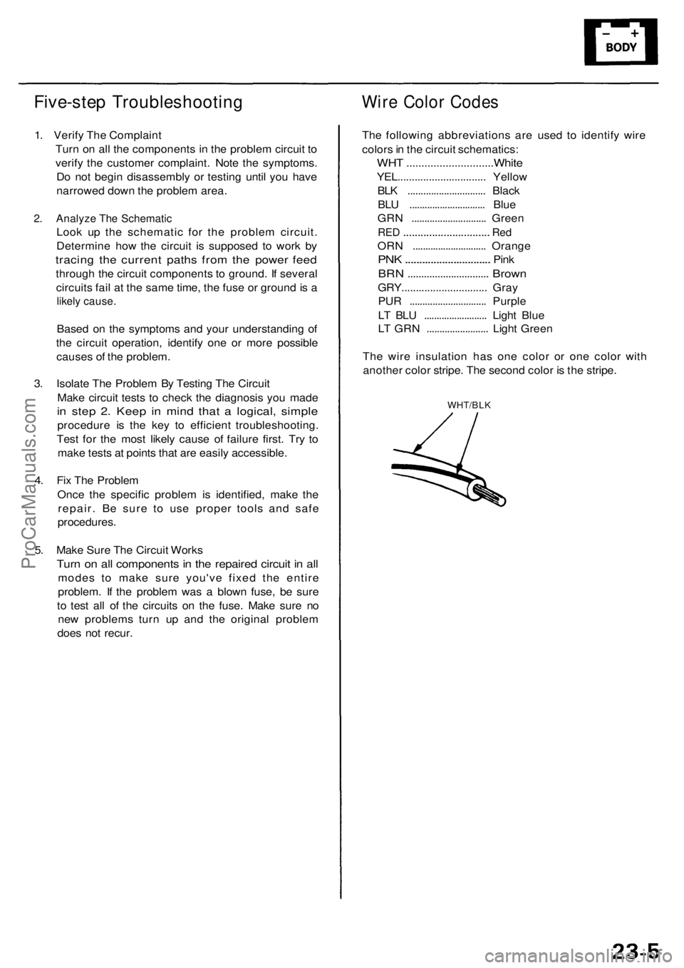
Th e wir e insulatio n ha s on e colo r o r on e colo r wit h
anothe r colo r stripe . Th e secon d colo r i s th e stripe .
WHT/BL K
ProCarManuals.com