1996 ACURA RL KA9 service reset
[x] Cancel search: service resetPage 142 of 1954

PGM-FI System
Primary Heated Oxygen Sensor (HO2S) (Sensor 1) (cont'd)
Troubleshooting Flowchart
Is DTC P0133 and/or P0153
indicated?
NO
YES
Intermittent failure, system is OK
at this time. Check for poor con-
nections or loose terminals at
C251, C254 (located at right shock
tower), C119 (right primary H02S
(Bank 1, Sensor 1)) or C126 (left
primary H02S (Bank 2, Sensor
1))*
and
PCM.
— The MIL has been reported on.
— DTC P0133 and/or P0153
stored.
Problem verification:
1. Do the PCM Reset Procedure.
2. Start the engine. Hold the
engine at 3,000 rpm with no
load (in Park or neutral) until
the radiator fan comes on.
3. Connect the SCS service con-
nector.
4. Test-drive under following
conditions.
— 55 mph (88 km/h) steady
speed
— Transmission in posi-
tion
— Until readiness code comes
on
Replace the primary HO2S (Sen-
sor 1).ProCarManuals.com
Page 158 of 1954

PGM-FI System
Barometric Pressure (Baro) Sensor
The HDS or the scan tool indicates Diagnostic Trouble Code (DTC) P2227: A range/performance problem in the
Barometric Pressure (BARO) Sensor circuit.
Is DTC P2227 indicated?
Intermittent failure, system is OK
at this time.
YES
Substitute a known-good PCM
and recheck. If symptom/indica-
tion goes away, replace the origi-
nal
PCM.
Problem verification:
1. Do the PCM reset procedure.
2. Connect the SCS service con-
nector.
3. Start the engine. Hold the
engine at 3,000 rpm with no
load (in Park or neutral) until
the radiator fan comes on,
then let it idle.
4. Test-drive with the transmis-
sion in position.
5. Accelerate for five seconds
using wide open throttle.
— The MIL has been reported on.
— DTC P2227 is stored.ProCarManuals.com
Page 230 of 1954

Muting Logi c
Wheneve r th e navigatio n syste m is givin g guidance ,
fron t speaker s ar e muted . Whe n th e voic e contro l sys -
te m is bein g used , al l o f th e speaker s ar e muted .
Whe n usin g On-Star , bot h th e audi o syste m an d th e
navigatio n syste m ar e muted , an d th e voic e contro l
switc h (TAL K an d BAC K buttons ) i s disabled .
Voice Contro l Limitation s
Before assumin g tha t a voic e contro l complain t i s hard -
war e related , ensur e tha t th e voic e contro l syste m is be -
in g operate d correctl y (se e "Voic e recognitio n doe s no t
work" , pag e 23-35) .
LCD Displa y Uni t Limitation s
• I n col d temperatures , th e displa y ma y sta y dar k fo r th e
firs t 2 o r 3 minute s unti l i t warm s up .
• Whe n th e displa y i s to o ho t becaus e o f direc t summe r
sunlight , i t wil l remai n dar k unti l th e temperatur e
drops .
• Whe n th e humidit y i s hig h an d th e interio r tempera -
tur e i s low , th e displa y ma y appea r cloudy . Th e dis -
pla y wil l clea r u p afte r som e use .
• Fingerprint s o n th e touc h pane l ma y sometime s b e
noticeabl e becaus e o f th e panel' s low-reflectio n coat -
ing. Whe n cleanin g th e panel , wip e i t gentl y wit h a
sof t cloth . T o avoi d scratchin g th e panel , d o no t ru b
to o hard , o r us e abrasiv e cleaner s o r sho p towels .
• Th e touc h pane l i s a n infrare d system , s o ther e i s n o
nee d t o pres s hard . I f a touc h switc h doe s no t functio n
immediately , shif t you r finge r slightly , an d touc h i t
again .
Note : Inpu t ma y b e affecte d b y direc t sunlight .
Symptom Duplicatio n
• Whe n th e sympto m ca n b e duplicated , follo w th e self -
diagnosti c procedure s an d th e appropriat e trou -
bleshootin g procedures .
• Whe n th e sympto m doe s no t reappea r o r onl y reap -
pear s intermittently , as k th e custome r abou t th e condi -
tion s whe n th e sympto m occured .
-Tr y t o establis h i f outsid e interferenc e ma y hav e
bee n th e cause .
-Tr y t o duplicat e th e sympto m unde r th e sam e condi -
tion s th e custome r wa s experiencing .
-Vibration , temperatur e extremes , an d moistur e (dew ,
humidity ) ar e factor s tha t ar e difficul t t o duplicate .
- Inspec t th e vehicl e fo r after-marke t electroni c device s
(vehicl e locators , amps , rada r detectors , etc) that
ma y b e hidden .
Service Precaution s
• Befor e disconnectin g th e battery , mak e sur e yo u hav e
th e anti-thef t code s fo r th e radi o an d th e navigatio n
system , an d writ e dow n th e frequencie s fo r th e radio' s
prese t buttons .
• Whe n th e batter y i s disconnected , th e interna l GP S
cloc k
is rese t to "0:00" . The cloc k will rese t to th e cor -
rec t tim e afte r th e syste m finishe s GP S initialization .
• Afte r reconnectin g th e battery , yo u hav e t o wai t t o ge t
the initia l signa l fro m th e satellite , whic h ma y tak e fro m
10 to 4 5 minutes . Follo w th e instruction s o n th e screen .
• Afte r reconnectin g th e battery , d o th e powe r windo w
control uni t resettin g procedure .
• Befor e returnin g th e vehicl e t o th e customer , ente r th e
radi o code , the n ente r th e customer' s radi o statio n
presets , an d se t th e clock . D o th e engin e contro l mod -
ul e (PCM ) idl e lear n procedure .
After Servicing-Ma p Matchin g
• Par k th e vehicl e in a n are a wher e th e GP S satellit e sig -
nal s wil l b e unobstructed . Mak e sur e th e GP S indica -
to r o n th e ma p scree n i s green .
• Driv e th e vehicl e 1 mil e befor e enterin g a destinatio n
an d confir m th e roa d bein g use d i s displaye d a t th e
botto m o f th e scree n (ma p matched) .
• Ente r th e deale r addres s an d confir m th e syste m
route s an d perform s normally .
• Clea r an y previou s destination s tha t ma y hav e bee n
entere d fo r testin g purposes .
Obtaining A Navigatio n DV D
If th e navigatio n DV D is los t o r damaged , o r yo u nee d a
yearl y updat e DVD , yo u hav e 2 way s t o purchas e one .
Yo u ca n eithe r cal l (888 ) 549-3798 , o r orde r on-lin e a t
www.Acura.com .
Both method s requir e a credi t card . Th e DV D fo r thi s
mode l ha s a n orang e label , an d canno t b e ordere d
throug h th e part s system . Th e followin g DVD s wil l no t
wor k in thi s navigatio n system :
• Earlie r mode l Acur a Navigatio n DVD s (blac k label )
• Ma p softwar e program s manufacture d b y othe r com -
panie s
• DV D movies , o r DVD s containin g audi o recording s
Updat e DVD s ar e availabl e fo r purchas e usuall y i n th e
fal l o f eac h year . The y ma y contai n th e following :
• Enhance d ma p an d Point s o f interes t (PO D coverag e
• Fixe s fo r mino r softwar e bug s
• Additiona l feature s
Note : Updat e i s o f cours e optional , an d ther e i s n o pro -
gra m to provid e fre e DVD s containin g yearl y mappin g
updates.
ProCarManuals.com
Page 671 of 1954
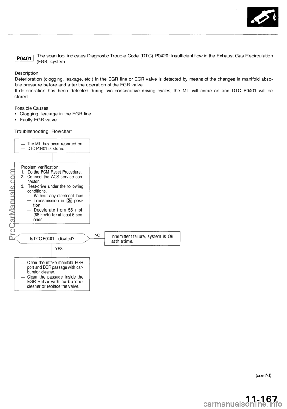
The scan tool indicates Diagnostic Trouble Code (DTC) P0420: Insufficient flow in the Exhaust Gas Recirculation
(EGR)
system.
Description
Deterioration (clogging, leakage, etc.) in the EGR line or EGR valve is detected by means of the changes in manifold abso-
lute pressure before and after the operation of the EGR valve.
If deterioration has been detected during two consecutive driving cycles, the MIL will come on and DTC P0401 will be
stored.
Possible Causes
• Clogging, leakage in the EGR line
• Faulty EGR valve
Troubleshooting Flowchart
Is DTC P0401 indicated?
Intermittent failure, system is OK
at this time.
YES
Clean the intake manifold EGR
port and EGR passage with car-
buretor cleaner.
Clean the passage inside the
EGR valve with carburetor
cleaner or replace the valve.
NO
Problem verification:
1. Do the PCM Reset Procedure.
2. Connect the ACS service con-
nector.
3. Test-drive under the following
conditions.
— Without any electrical load
— Transmission in posi-
tion
— Decelerate from 55 mph
(88 km/h) for at least 5 sec-
onds.
The MIL has been reported on.
DTC P0401 is stored.ProCarManuals.com
Page 760 of 1954
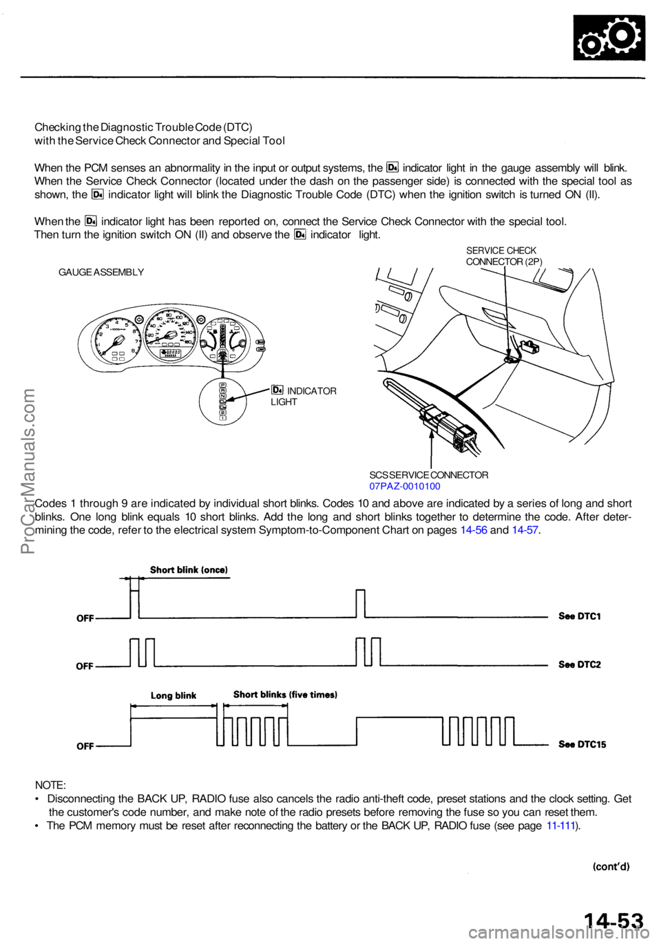
Checking th e Diagnosti c Troubl e Cod e (DTC )
wit h th e Servic e Chec k Connecto r an d Specia l Too l
Whe n th e PC M sense s a n abnormalit y in th e inpu t o r outpu t systems , th e indicato r ligh t i n th e gaug e assembl y wil l blink .
Whe n th e Servic e Chec k Connecto r (locate d unde r th e das h o n th e passenge r side ) i s connecte d wit h th e specia l too l a s
shown , th e indicato r ligh t wil l blin k th e Diagnosti c Troubl e Cod e (DTC ) whe n th e ignitio n switc h i s turne d O N (II) .
Whe n th e indicato r ligh t ha s bee n reporte d on , connec t th e Servic e Chec k Connecto r wit h th e specia l tool .
Then tur n th e ignitio n switc h O N (II ) an d observ e th e indicato r light .
INDICATO RLIGHT
Code s 1 throug h 9 ar e indicate d b y individua l shor t blinks . Code s 1 0 an d abov e ar e indicate d b y a serie s o f lon g an d shor t
blinks . On e lon g blin k equal s 1 0 shor t blinks . Ad d th e lon g an d shor t blink s togethe r t o determin e th e code . Afte r deter -
minin g th e code , refe r t o th e electrica l syste m Symptom-to-Componen t Char t o n page s 14-5 6 an d 14-57 .
NOTE :
• Disconnectin g th e BAC K UP , RADI O fus e als o cancel s th e radi o anti-thef t code , prese t station s an d th e cloc k setting . Ge t
th e customer' s cod e number , an d mak e not e o f th e radi o preset s befor e removin g th e fus e s o yo u ca n rese t them .
• Th e PC M memor y mus t b e rese t afte r reconnectin g th e batter y o r th e BAC K UP , RADI O fus e (se e pag e 11-111 ).
SC S SERVIC E CONNECTO R07PAZ-001010 0
GAUGE ASSEMBL Y
SERVICE CHEC KCONNECTO R (2P )
ProCarManuals.com
Page 1367 of 1954
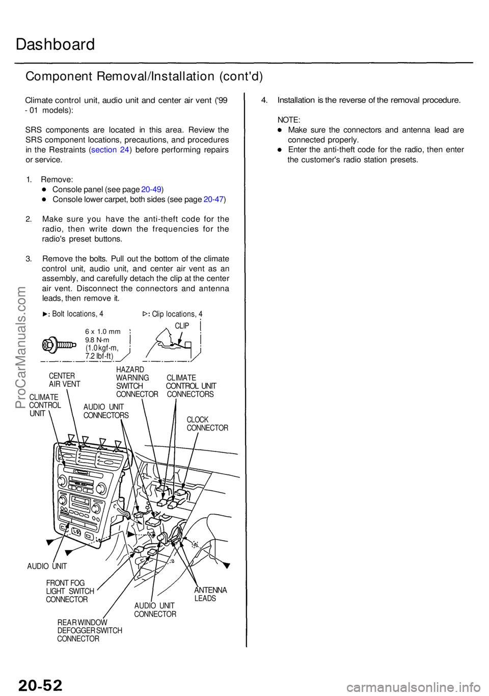
Dashboard
Componen t Removal/Installatio n (cont'd )
Climate contro l unit , audi o uni t an d cente r ai r ven t ('9 9
- 0 1 models) :
SR S component s ar e locate d i n thi s area . Revie w th e
SR S componen t locations , precautions , an d procedure s
i n th e Restraint s ( sectio n 24 ) befor e performin g repair s
o r service .
1 . Remove :
Consol e pane l (se e pag e 20-49 )
Consol e lowe r carpet , bot h side s (se e pag e 20-47 )
2.
3.
Mak e sur e yo u hav e th e anti-thef t cod e fo r th e
radio , the n writ e dow n th e frequencie s fo r th e
radio' s prese t buttons .
Remov e th e bolts . Pul l ou t th e botto m o f th e climat e
contro l unit , audi o unit , an d cente r ai r ven t a s a n
assembly , an d carefull y detac h th e cli p a t th e cente r
ai r vent . Disconnec t th e connector s an d antenn a
leads , the n remov e it .
Bol t locations , 4
6 x 1. 0 m m9.8 N- m(1.0 kgf-m ,
7. 2 Ibf-ft ) Cli
p locations , 4
CLI P
CENTE RAIR VEN T
CLIMAT ECONTRO LUNIT
HAZAR DWARNIN G CLIMAT ESWITCH CONTRO L UNI TCONNECTO R CONNECTOR S
CLOCKCONNECTO R
AUDIO UNI T
FRON T FO G
LIGH T SWITC H
CONNECTO R
REA R WINDO W
DEFOGGE R SWITC H
CONNECTO R
ANTENNALEADSAUDIO UNI TCONNECTO R
4. Installatio n is th e revers e o f th e remova l procedure .
NOTE:
Make sur e th e connector s an d antenn a lea d ar e
connecte d properly .
Ente r th e anti-thef t cod e fo r th e radio , the n ente r
th e customer' s radi o statio n presets .
AUDIO UNI T
CONNECTOR S
ProCarManuals.com
Page 1373 of 1954
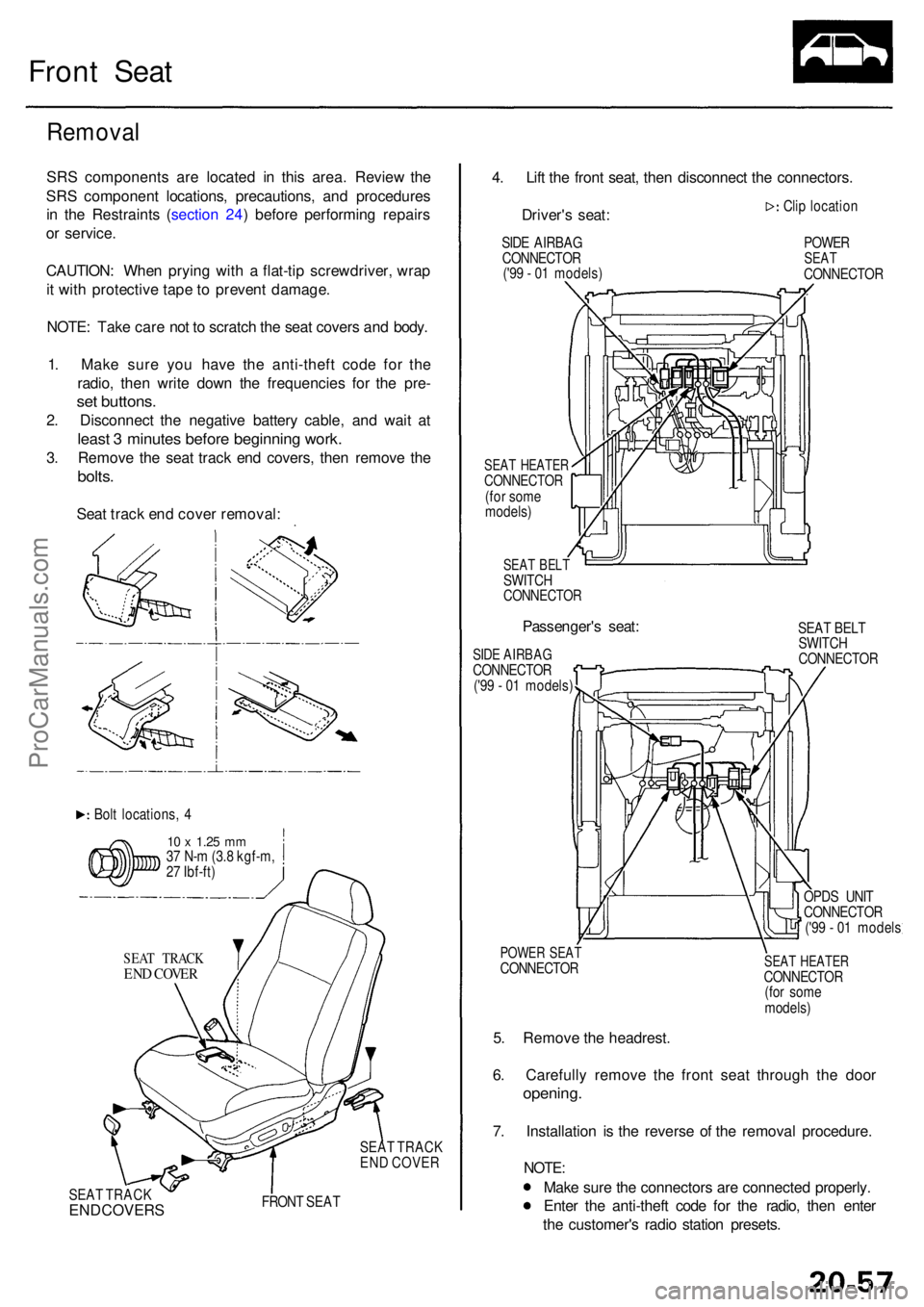
Front Sea t
Remova l
SRS component s ar e locate d i n thi s area . Revie w th e
SR S componen t locations , precautions , an d procedure s
i n th e Restraint s ( sectio n 24 ) befor e performin g repair s
o r service .
CAUTION : Whe n pryin g wit h a flat-ti p screwdriver , wra p
i t wit h protectiv e tap e t o preven t damage .
NOTE : Tak e car e no t t o scratc h th e sea t cover s an d body .
1 . Mak e sur e yo u hav e th e anti-thef t cod e fo r th e
radio , the n writ e dow n th e frequencie s fo r th e pre -
set buttons .
2. Disconnec t th e negativ e batter y cable , an d wai t a t
leas t 3 minute s befor e beginnin g work .
3. Remov e th e sea t trac k en d covers , the n remov e th e
bolts .
Seat trac k en d cove r removal :
Bolt locations , 4
1 0 x 1.2 5 mm37 N- m (3. 8 kgf-m ,
2 7 Ibf-ft )
SEA T TRAC K
END COVE R
SEAT TRAC K
EN D COVE R
SEA T TRAC K
END COVER S FRON T SEA T
4. Lif t th e fron t seat , the n disconnec t th e connectors .
Driver' s seat :
SIDE AIRBA G
CONNECTO R
('9 9 - 0 1 models )
SEAT HEATE RCONNECTO R(for som e
models )
SEAT BEL TSWITC HCONNECTO R
Passenger's seat :
SIDE AIRBA GCONNECTO R('99 - 0 1 models ) Cli
p locatio n
POWERSEATCONNECTO R
SEA T BEL T
SWITC H
CONNECTO R
POWER SEA TCONNECTO R
5. Remov e th e headrest .
6 . Carefull y remov e th e fron t sea t throug h th e doo r
opening .
7. Installatio n i s th e revers e o f th e remova l procedure .
NOTE:
Make sur e th e connector s ar e connecte d properly .
Ente r th e anti-thef t cod e fo r th e radio , the n ente r
th e customer' s radi o statio n presets .
SEAT HEATE RCONNECTO R
(fo r som e
models )
OPD
S UNI T
CONNECTO R
('9 9 - 0 1 model s
ProCarManuals.com
Page 1516 of 1954
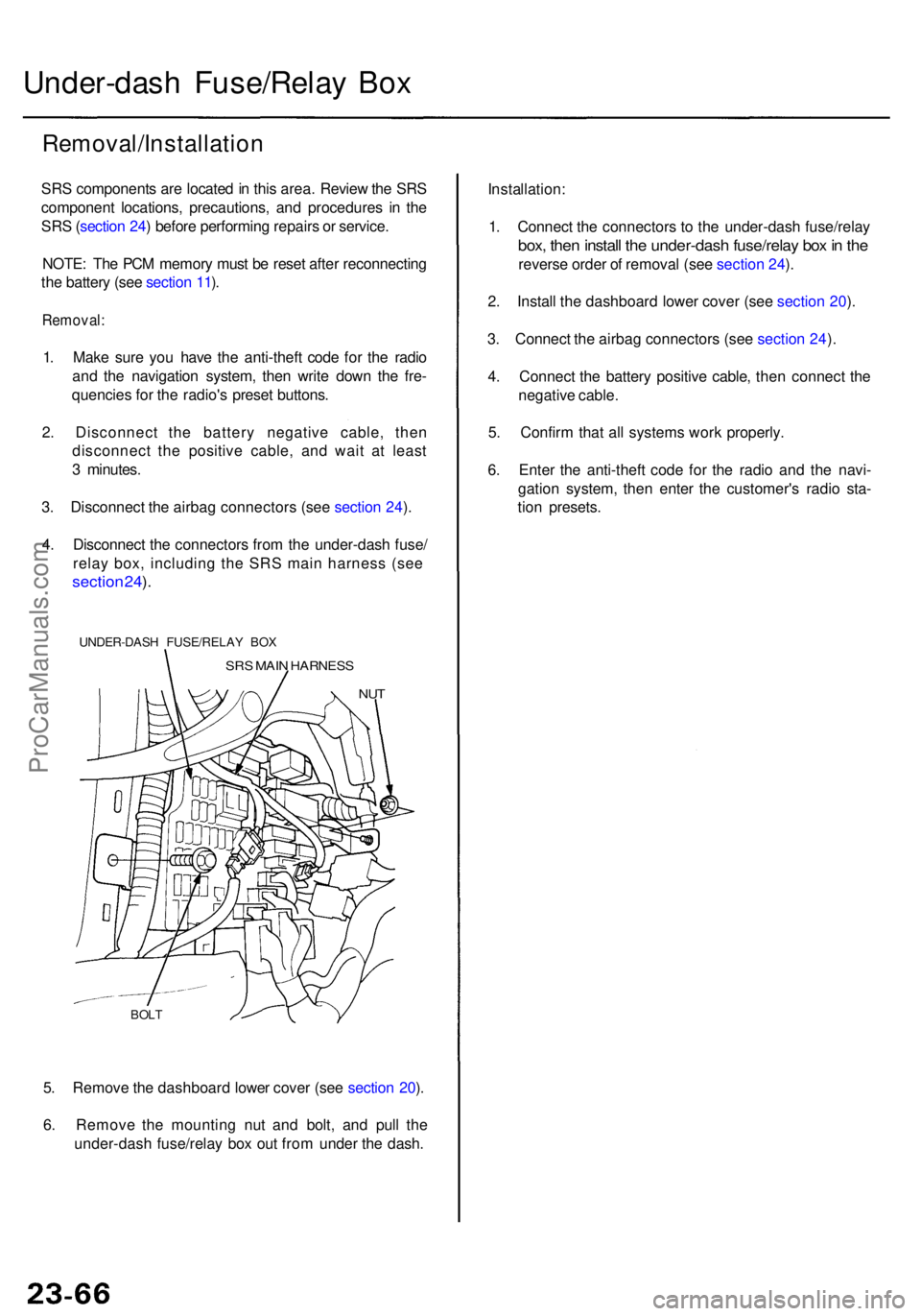
5. Remov e th e dashboar d lowe r cove r (se e sectio n 20 ).
6 . Remov e th e mountin g nu t an d bolt , an d pul l th e
under-das h fuse/rela y bo x ou t fro m unde r th e dash .
BOLT
Under-das h Fuse/Rela y Bo x
Removal/Installatio n
SRS component s ar e locate d in thi s area . Revie w th e SR S
componen t locations , precautions , an d procedure s i n th e
SR S (sectio n 24 ) befor e performin g repair s o r service .
NOTE : Th e PC M memor y mus t b e rese t afte r reconnectin g
th e batter y (se e sectio n 11 ).
Removal :
1. Mak e sur e yo u hav e th e anti-thef t cod e fo r th e radi o
an d th e navigatio n system , the n writ e dow n th e fre -
quencie s fo r th e radio' s prese t buttons .
2 . Disconnec t th e batter y negativ e cable , the n
disconnec t th e positiv e cable , an d wai t a t leas t
3 minutes .
3 . Disconnec t th e airba g connector s (se e sectio n 24 ).
4 . Disconnec t th e connector s fro m th e under-das h fuse /
relay box, including the SRS main harness (see
sectio n 24 ).
UNDER-DAS H FUSE/RELA Y BO X
SRS MAI N HARNES S
NUT
Installation :
1 . Connec t th e connector s t o th e under-das h fuse/rela y
box, the n instal l th e under-das h fuse/rela y bo x in th e
revers e orde r o f remova l (se e sectio n 24 ).
2 . Instal l th e dashboar d lowe r cove r (se e sectio n 20 ).
3 . Connec t th e airba g connector s (se e sectio n 24 ).
4 . Connec t th e batter y positiv e cable , the n connec t th e
negativ e cable .
5 . Confir m tha t al l system s wor k properly .
6 . Ente r th e anti-thef t cod e fo r th e radi o an d th e navi -
gatio n system , the n ente r th e customer' s radi o sta -
tio n presets .
ProCarManuals.com