Page 1520 of 1954

Ignition Switc h
Test
SRS component s ar e locate d i n thi s area . Revie w th e
SR S componen t locations , precautions , an d procedure s
i n th e SR S ( sectio n 24 ) befor e performin g repair s o r
service .
NOTE: Th e PC M memor y mus t b e rese t afte r reconnectin g
th e batter y (se e sectio n 11 ).
1 . Mak e sur e yo u hav e th e anti-thef t cod e fo r th e radi o
an d th e navigatio n system , the n writ e dow n th e fre -
quencie s fo r th e radio' s prese t buttons .
2 . Disconnec t th e batter y negativ e cable .
3 . Remov e th e dashboar d lowe r cove r (se e sectio n 20 ).
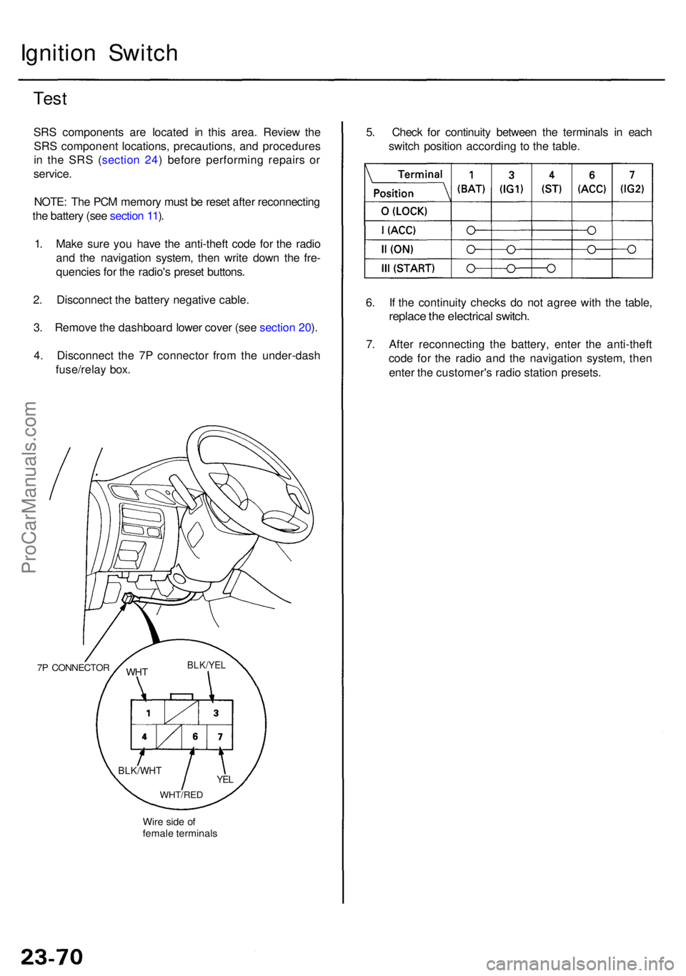
4 . Disconnec t th e 7 P connecto r fro m th e under-das h
fuse/rela y box .
7P CONNECTO R
Wire sid e o f
femal e terminal s
WHTBLK/YE L
YEL
WHT/RE D
BLK/WH T
5. Chec k fo r continuit y betwee n th e terminal s i n eac h
switc h positio n accordin g t o th e table .
6 . I f th e continuit y check s d o no t agre e wit h th e table ,
replac e th e electrica l switch .
7. Afte r reconnectin g th e battery , ente r th e anti-thef t
cod e fo r th e radi o an d th e navigatio n system , the n
ente r th e customer' s radi o statio n presets .
ProCarManuals.com
Page 1521 of 1954

8. Afte r reconnectin g th e battery , ente r th e anti-thef t
cod e fo r th e radi o an d th e navigatio n system , the n
ente r th e customer' s radi o statio n presets .
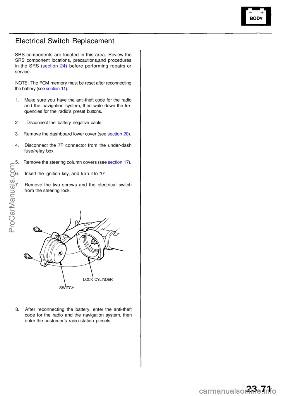
SWITCH
LOCK CYLINDE R
Electrical Switc h Replacemen t
SRS component s ar e locate d i n thi s area . Review the
SR S componen t locations , precautions,an d procedure s
i n th e SR S ( sectio n 24 ) befor e performin g repair s o r
service .
NOTE: Th e PC M memor y mus t b e rese t afte r reconnectin g
th e batter y (se e sectio n 11 ).
1 . Mak e sur e yo u hav e th e anti-thef t cod e fo r th e radi o
an d th e navigatio n system , the n writ e dow n th e fre -
quencie s fo r th e radio' s prese t buttons .
2 . Disconnec t th e batter y negativ e cable .
3 . Remov e th e dashboar d lowe r cove r (se e sectio n 20 ).
4 . Disconnec t th e 7 P connecto r fro m th e under-das h
fuse/rela y box .
5 . Remov e th e steerin g colum n cover s (se e sectio n 17 ).
6 . Inser t th e ignitio n key , an d tur n it t o "0" .
7 . Remov e th e tw o screw s an d th e electrica l switc h
fro m th e steerin g lock .
ProCarManuals.com
Page 1567 of 1954

Stereo Soun d Syste m
Audio Uni t Remova l
SRS component s ar e locate d i n thi s area . Revie w th e
SR S componen t locations , precautions , an d procedure s
i n th e SR S ( sectio n 24 ) befor e performin g repair s o r
service .
With navigatio n system :
1 . Mak e sur e yo u hav e th e anti-thef t cod e fo r th e radi o
an d th e navigatio n system , the n writ e dow n th e fre -
quencie s fo r th e radio' s prese t buttons .
2 . Remov e th e navigatio n pane l an d audi o pane l
assembl y (se e sectio n 20 ).
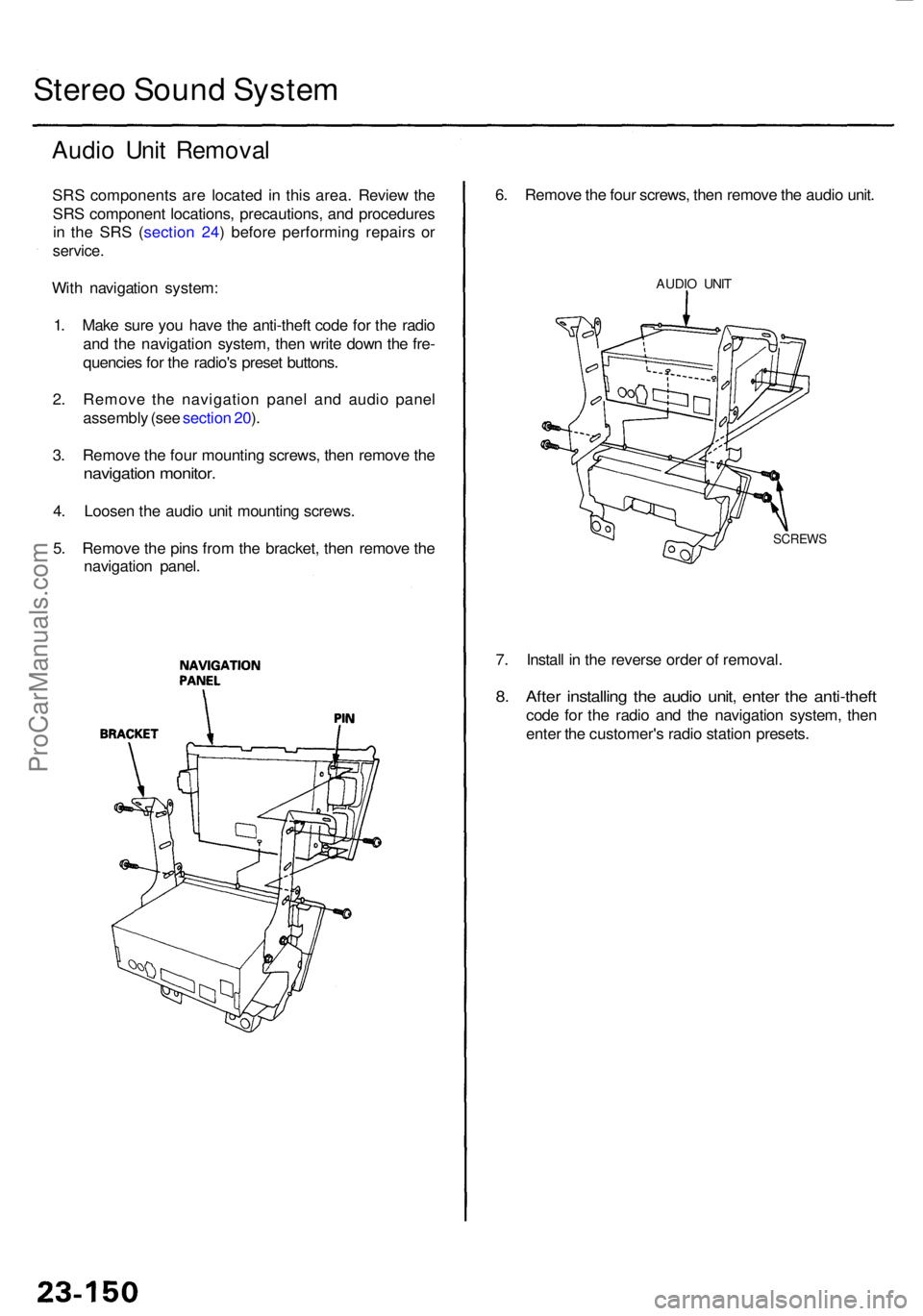
3 . Remov e th e fou r mountin g screws , the n remov e th e
navigatio n monitor .
4. Loose n th e audi o uni t mountin g screws .
5 . Remov e th e pin s fro m th e bracket , the n remov e th e
navigatio n panel .
7. Instal l i n th e revers e orde r o f removal .
8. Afte r installin g th e audi o unit , ente r th e anti-thef t
code fo r th e radi o an d th e navigatio n system , the n
ente r th e customer' s radi o statio n presets .
6
. Remov e th e fou r screws , the n remov e th e audi o unit .
AUDI O UNI T
SCREW S
ProCarManuals.com
Page 1779 of 1954

Front Sea t Bel t
Removal/Installatio n
SRS component s ar e locate d in thi s area . Revie w th e SR S
componen t locations , precautions , an d procedure s i n thi s
( sectio n 24 ) befor e performin g repair s o r service .
CAUTION : Chec k th e fron t sea t belt s fo r damage , an d
replac e the n if necessary . B e carefu l no t t o damag e the m
durin g remova l an d installation .
Fron t sea t belt :
1. Mak e sur e yo u hav e th e anti-thef t cod e fo r th e
radio , the n writ e dow n th e frequencie s fo r th e pre -
se t buttons .
2 . Disconnec t th e negativ e batter y cable , an d wai t a t
leas t 3 minute s befor e beginnin g work .
3 . Slid e th e fron t sea t forwar d fully .
4 . Remove :
• Fron t an d rea r sid e tri m (se e sectio n 20 )
• Fron t an d rea r doo r tri m (se e sectio n 20 )
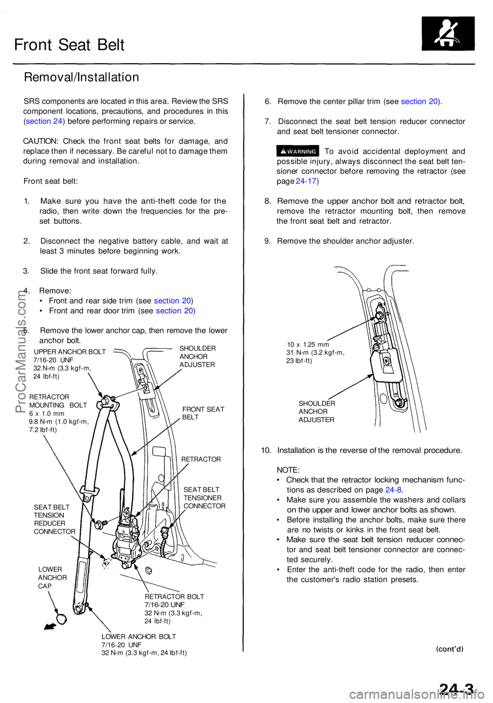
5 . Remov e th e lowe r ancho r cap , the n remov e th e lowe r
ancho r bolt .
SHOULDE R
ANCHO R
ADJUSTE R
UPPER ANCHO R BOL T
7/16-2 0 UN F
3 2 N- m (3. 3 kgf-m ,
24 Ibf-ft )
RETRACTO RMOUNTING BOL T6 x 1. 0 m m9.8 N- m (1. 0 kgf-m ,
7. 2 Ibf-ft )
SEA T BEL T
TENSIO NREDUCE RCONNECTO R
LOWERANCHO RCAP
FRON T SEA TBELT
RETRACTO R
SEAT BEL T
TENSIONE R
CONNECTO R
RETRACTOR BOL T7/16-2 0 UN F32 N- m (3. 3 kgf-m ,24 Ibf-ft )
LOWE R ANCHO R BOL T
7/16-2 0 UN F
3 2 N- m (3. 3 kgf-m , 2 4 Ibf-ft )
6. Remov e th e cente r pilla r tri m (se e sectio n 20 ).
7 . Disconnec t th e sea t bel t tensio n reduce r connecto r
an d sea t bel t tensione r connector .
T o avoi d accidenta l deploymen t an d
possibl e injury , alway s disconnec t th e sea t bel t ten -
sione r connecto r befor e removin g th e retracto r (se e
pag e 24-17 )
8. Remov e th e uppe r ancho r bol t an d retracto r bolt ,
remov e th e retracto r mountin g bolt , the n remov e
th e fron t sea t bel t an d retractor .
9 . Remov e th e shoulde r ancho r adjuster .
10 x 1.2 5 mm31 N- m (3. 2 kgf-m ,
2 3 Ibf-ft )
SHOULDE R
ANCHO R
ADJUSTE R
10. Installatio n is th e revers e o f th e remova l procedure .
NOTE:
• Chec k tha t th e retracto r lockin g mechanis m func -
tions a s described on pag e 24-8 .
• Mak e sur e yo u assembl e th e washer s an d collar s
on th e uppe r an d lowe r ancho r bolt s a s shown .
• Befor e installin g th e ancho r bolts , mak e sur e ther e
ar e n o twist s o r kink s i n th e fron t sea t belt .
• Mak e sur e th e sea t bel t tensio n reduce r connec -
tor an d sea t bel t tensione r connecto r ar e connec -
te d securely .
• Ente r th e anti-thef t cod e fo r th e radio , the n ente r
th e customer' s radi o statio n presets .
ProCarManuals.com