1996 ACURA RL KA9 ECU
[x] Cancel search: ECUPage 1753 of 1954
Cyclic Dia g
I n thi s test , chec k th e followin g item s repeatedly :
• Navigatio n uni t chec k (Nav i ECU )
• Monito r chec k (excep t switc h test )
T o exi t thi s test , pres s th e CANCE L ke y
In-Lin e Dia g
I n thi s test , yo u can chec k followin g item :
• Syste m link s
• Ca r statu s
• Ya w rat e
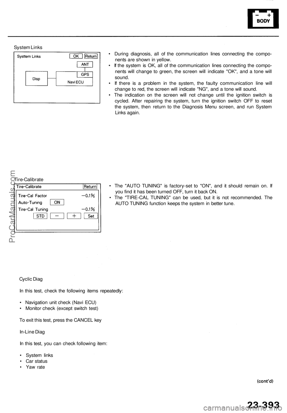
Syste m Link s
• Durin g diagnosis , al l o f th e communicatio n line s connectin g th e compo -
nent s ar e show n in yellow .
• I f th e syste m is OK , al l o f th e communicatio n line s connectin g th e compo -
nent s wil l chang e t o green , th e scree n wil l indicat e "OK" , an d a ton e wil l
sound .
• I f ther e i s a proble m in th e system , th e fault y communicatio n lin e wil l
chang e to red , th e scree n wil l indicat e "NG" , an d a ton e wil l sound .
• Th e indicatio n o n th e scree n wil l no t chang e unti l th e ignitio n switc h i s
cycled . Afte r repairin g th e system , tur n th e ignitio n switc h OF F t o rese t
th e system , the n retur n t o th e Diagnosi s Men u screen , an d ru n Syste m
Link s again .
• Th e "AUT O TUNING " i s factory-se t t o "ON" , an d i t shoul d remai n on . I f
yo u fin d it ha s bee n turne d OFF , tur n it bac k ON .
• Th e "TIRE-CA L TUNING " ca n b e used , bu t i t i s no t recommended . Th e
AUT O TUNIN G functio n keep s th e syste m in bette r tune .
Tire-Calibrat e
ProCarManuals.com
Page 1779 of 1954
Front Sea t Bel t
Removal/Installatio n
SRS component s ar e locate d in thi s area . Revie w th e SR S
componen t locations , precautions , an d procedure s i n thi s
( sectio n 24 ) befor e performin g repair s o r service .
CAUTION : Chec k th e fron t sea t belt s fo r damage , an d
replac e the n if necessary . B e carefu l no t t o damag e the m
durin g remova l an d installation .
Fron t sea t belt :
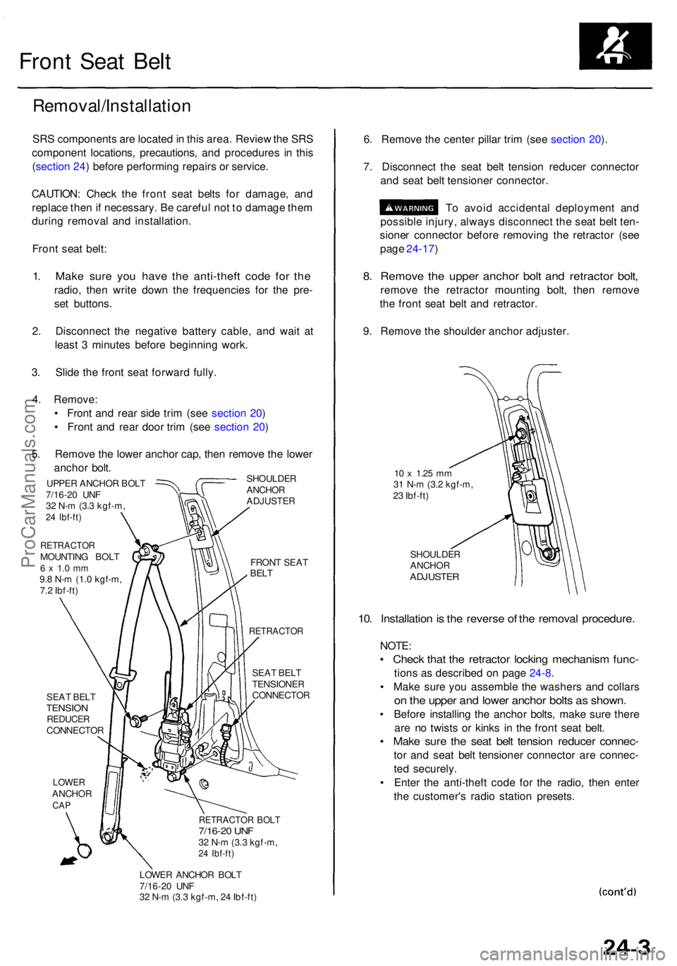
1. Mak e sur e yo u hav e th e anti-thef t cod e fo r th e
radio , the n writ e dow n th e frequencie s fo r th e pre -
se t buttons .
2 . Disconnec t th e negativ e batter y cable , an d wai t a t
leas t 3 minute s befor e beginnin g work .
3 . Slid e th e fron t sea t forwar d fully .
4 . Remove :
• Fron t an d rea r sid e tri m (se e sectio n 20 )
• Fron t an d rea r doo r tri m (se e sectio n 20 )
5 . Remov e th e lowe r ancho r cap , the n remov e th e lowe r
ancho r bolt .
SHOULDE R
ANCHO R
ADJUSTE R
UPPER ANCHO R BOL T
7/16-2 0 UN F
3 2 N- m (3. 3 kgf-m ,
24 Ibf-ft )
RETRACTO RMOUNTING BOL T6 x 1. 0 m m9.8 N- m (1. 0 kgf-m ,
7. 2 Ibf-ft )
SEA T BEL T
TENSIO NREDUCE RCONNECTO R
LOWERANCHO RCAP
FRON T SEA TBELT
RETRACTO R
SEAT BEL T
TENSIONE R
CONNECTO R
RETRACTOR BOL T7/16-2 0 UN F32 N- m (3. 3 kgf-m ,24 Ibf-ft )
LOWE R ANCHO R BOL T
7/16-2 0 UN F
3 2 N- m (3. 3 kgf-m , 2 4 Ibf-ft )
6. Remov e th e cente r pilla r tri m (se e sectio n 20 ).
7 . Disconnec t th e sea t bel t tensio n reduce r connecto r
an d sea t bel t tensione r connector .
T o avoi d accidenta l deploymen t an d
possibl e injury , alway s disconnec t th e sea t bel t ten -
sione r connecto r befor e removin g th e retracto r (se e
pag e 24-17 )
8. Remov e th e uppe r ancho r bol t an d retracto r bolt ,
remov e th e retracto r mountin g bolt , the n remov e
th e fron t sea t bel t an d retractor .
9 . Remov e th e shoulde r ancho r adjuster .
10 x 1.2 5 mm31 N- m (3. 2 kgf-m ,
2 3 Ibf-ft )
SHOULDE R
ANCHO R
ADJUSTE R
10. Installatio n is th e revers e o f th e remova l procedure .
NOTE:
• Chec k tha t th e retracto r lockin g mechanis m func -
tions a s described on pag e 24-8 .
• Mak e sur e yo u assembl e th e washer s an d collar s
on th e uppe r an d lowe r ancho r bolt s a s shown .
• Befor e installin g th e ancho r bolts , mak e sur e ther e
ar e n o twist s o r kink s i n th e fron t sea t belt .
• Mak e sur e th e sea t bel t tensio n reduce r connec -
tor an d sea t bel t tensione r connecto r ar e connec -
te d securely .
• Ente r th e anti-thef t cod e fo r th e radio , the n ente r
th e customer' s radi o statio n presets .
ProCarManuals.com
Page 1787 of 1954
Child Seat Tether Anchor
Installation — '96 - 99 Models
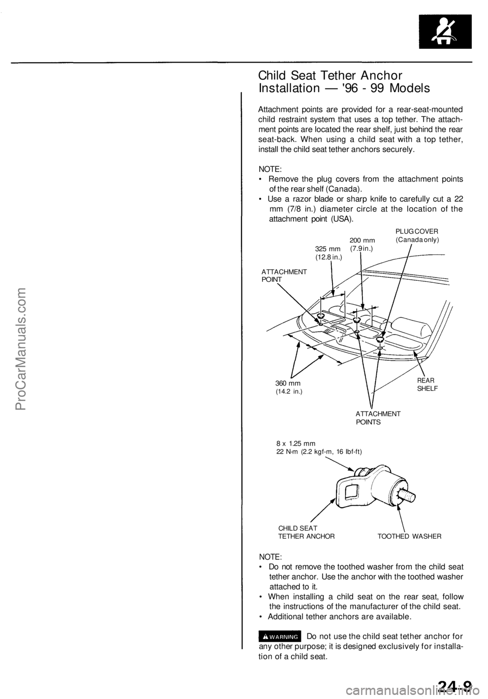
Attachment points are provided for a rear-seat-mounted
child restraint system that uses a top tether. The attach-
ment points are located the rear shelf, just behind the rear
seat-back. When using a child seat with a top tether,
install the child seat tether anchors securely.
NOTE:
• Remove the plug covers from the attachment points
of the rear shelf (Canada).
• Use a razor blade or sharp knife to carefully cut a 22
mm (7/8 in.) diameter circle at the location of the
attachment point (USA).
325 mm
(12.8 in.)
200 mm
(7.9 in.)
PLUG COVER
(Canada only)
ATTACHMENT
POINT
360 mm
(14.2 in.)
REAR
SHELF
ATTACHMENT
POINTS
8 x
1.25
mm
22 N-m (2.2 kgf-m, 16 Ibf-ft)
CHILD SEAT
TETHER ANCHOR
TOOTHED WASHER
NOTE:
• Do not remove the toothed washer from the child seat
tether anchor. Use the anchor with the toothed washer
attached to it.
• When installing a child seat on the rear seat, follow
the instructions of the manufacturer of the child seat.
• Additional tether anchors are available.
Do not use the child seat tether anchor for
any other purpose; it is designed exclusively for installa-
tion of a child seat.ProCarManuals.com
Page 1792 of 1954
Description
SRS Airbag System - '96 - 98 Models
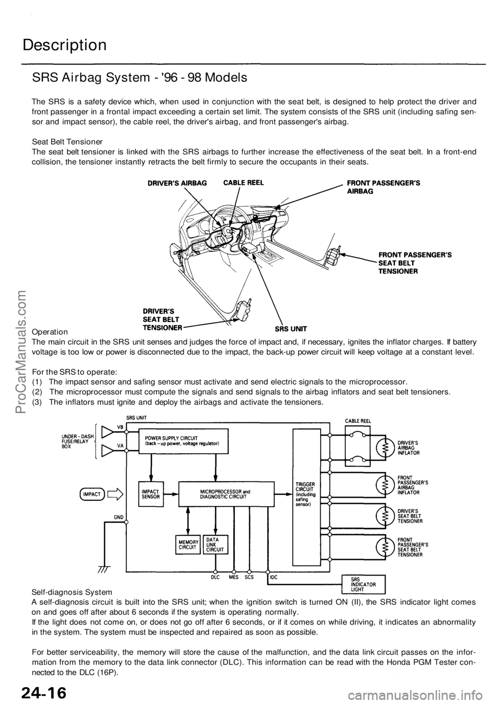
The SRS is a safety device which, when used in conjunction with the seat belt, is designed to help protect the driver and
front passenger in a frontal impact exceeding a certain set limit. The system consists of the SRS unit (including safing sen-
sor and impact sensor), the cable reel, the driver's airbag, and front passenger's airbag.
Seat Belt Tensioner
The seat belt tensioner is linked with the SRS airbags to further increase the effectiveness of the seat belt. In a front-end
collision, the tensioner instantly retracts the belt firmly to secure the occupants in their seats.
Operation
The main circuit in the SRS unit senses and judges the force of impact and, if necessary, ignites the inflator charges. If battery
voltage is too low or power is disconnected due to the impact, the back-up power circuit will keep voltage at a constant level.
For the SRS to operate:
(1) The impact sensor and safing sensor must activate and send electric signals to the microprocessor.
(2) The microprocessor must compute the signals and send signals to the airbag inflators and seat belt tensioners.
(3) The inflators must ignite and deploy the airbags and activate the tensioners.
Self-diagnosis System
A self-diagnosis circuit is built into the SRS unit; when the ignition switch is turned ON (II), the SRS indicator light comes
on and goes off after about 6 seconds if the system is operating normally.
If the light does not come on, or does not go off after 6 seconds, or if it comes on while driving, it indicates an abnormality
in the system. The system must be inspected and repaired as soon as possible.
For better serviceability, the memory will store the cause of the malfunction, and the data link circuit passes on the infor-
mation from the memory to the data link connector (DLC). This information can be read with the Honda PGM Tester con-
nected to the DLC (16P).ProCarManuals.com
Page 1793 of 1954
SRS Airba g Syste m - '9 9 - 0 1 Model s
SRS Airba g
The SR S is a safet y devic e which , whe n use d i n conjunctio n wit h th e sea t belt , i s designe d t o hel p protec t th e drive r an d
fron t passenge r i n a fronta l impac t exceedin g a certai n se t limit . Th e syste m consist s o f th e SR S uni t (including safing sen -
so r an d fron t impac t sensor) , th e cabl e reel , th e driver' s airba g an d fron t passenger' s airbag .
Sid e Airbag s
Sid e airbag s locate d i n eac h fron t seat-bac k ca n hel p protec t th e uppe r tors o o f th e drive r o r fron t sea t passenge r during a
moderat e t o sever e sid e impact . Sensor s i n eac h doo r sil l an d i n th e SR S uni t detec t suc h a n impac t an d instantl y inflat e
th e driver' s o r th e passenger' s sid e airbag . Onl y on e sid e airba g wil l deplo y durin g a sid e impact . I f th e impac t i s o n th e
passenger' s side , th e passenger' s sid e airba g wil l deplo y eve n if ther e is n o passenger .
Th e sid e airba g syste m als o include s a n Occupan t Positio n Detectio n Syste m (OPDS) . Thi s syste m consist s o f sensor s an d
a contro l uni t locate d i n th e fron t passenger' s seat-back . Th e contro l uni t send s occupan t heigh t an d positio n dat a t o th e
SR S unit . I f th e SR S uni t determine s tha t th e fron t passenger' s hea d i s i n th e deploymen t pat h o f th e sid e airbag , i t wil l
automaticall y disabl e th e airbag . Whe n th e sid e airba g i s disabled , th e Sid e Airba g indicato r ligh t i n th e gaug e assembl y
alert s th e drive r tha t th e passenger' s sid e airba g wil l no t deplo y i n a sid e impact .
Sea t Bel t Tensione r
Th e sea t bel t tensione r i s linke d wit h th e SR S airbag s t o furthe r increas e th e effectivenes s o f th e sea t belt . I n a front-en d
collision , th e tensione r instantl y retract s th e bel t firml y t o secur e th e occupant s i n thei r seats .
Operatio n
The mai n circui t i n th e SR S uni t sense s an d judge s th e forc e o f impac t and , i f necessary , ignite s th e inflato r charges . I f bat -
ter y voltag e i s to o lo w o r powe r i s disconnecte d du e t o th e impact , th e voltag e regulato r an d th e back-u p powe r circui t
respectivel y wil l kee p voltag e a t a constan t level .
Fo r th e SR S to operate :
Airba g an d Sea t Bel t Tensione r
(1 ) Th e fronta l impac t senso r mus t activate , an d sen d electri c signal s t o th e microprocessor .
(2 ) Th e microprocesso r mus t comput e th e signals , an d dependin g o n th e severit y o f th e collisio n an d whethe r th e sea t
bel t buckl e switc h i s O N o r OFF , i t send s th e appropriat e signal s t o th e airba g inflator s an d sea t bel t tensioners .
(3 ) Th e inflator s tha t receive d signal s mus t ignit e an d deplo y th e units .
Sid e Airba g
(1 ) Th e sid e impac t sensor s mus t activate , an d sen d electri c signal s t o th e microprocessor .
(2 ) Th e microprocesso r mus t comput e th e signal s an d sen d the m to th e sid e airba g inflators . Howeve r th e microproces -
so r cut s of f th e signal s t o th e fron t passenger' s sid e airba g i f th e SR S uni t determine s tha t th e fron t passenger' s hea d
i s i n th e deploymen t pat h o f th e sid e airbag .
(3 ) Th e inflato r tha t receive d th e signa l mus t ignit e an d deplo y th e sid e airbag .
ProCarManuals.com
Page 1795 of 1954
Precautions/Procedures
General Precaution s
• Carefull y inspec t an y SR S par t befor e yo u instal l it . D o
no t instal l an y par t tha t show s sign s o f bein g droppe d
o r improperl y handled , suc h a s dents , crack s o r defor -
mation :
Airbag s (fronta l airbag s an d sid e airbags )
Cabl e ree l
SRS uni t
Sea t bel t tensioner s
• Us e onl y a digita l multimete r t o chec k th e system . I f
it' s no t a Hond a multimeter , mak e sur e it s outpu t i s
1 0 m A (0.0 1 A ) o r les s whe n switche d t o th e smalles t
valu e i n th e ohmmete r range . A teste r wit h a highe r
output coul d damag e th e airba g circui t o r caus e acci -
denta l deploymen t an d possibl e injury .
• D o no t instal l use d SR S part s fro m anothe r vehicle .
Whe n makin g SR S repairs , us e onl y ne w parts .
• Excep t whe n performin g electrica l inspections ,
alway s disconnec t bot h th e negativ e cabl e an d posi -
tive cabl e fro m th e battery , an d wai t a t leas t 3 min -
utes befor e beginnin g work .
• Replacemen t o f th e combinatio n ligh t an d wiper /
washe r switche s an d cruis e contro l switc h ca n b e
don e withou t removin g th e steerin g wheel :
For combinatio n ligh t an d wiper/washe r switc h
replacement , se e sectio n 23 .
Fo r cruis e contro l set/resume/cance l switc h
replacement , se e sectio n 4 .
• Wheneve r th e ignitio n switc h is O N (II) , o r ha s bee n
turne d OF F fo r les s tha n 3 minutes , b e carefu l no t t o
bum p th e SR S unit ; th e airbag s coul d accidentall y
deplo y an d caus e damag e o r injury .
• Wheneve r th e airbag s hav e bee n activated , replac e
th e sea t bel t tensioner s an d th e SR S unit .
• Th e origina l radi o ha s a code d thef t protectio n circuit .
B e sur e to ge t th e customer' s cod e numbe r befor e dis -
connectin g th e batter y cables .
• Th e PC M memor y mus t b e rese t afte r reconnectin g th e
batter y (se e pag e 11-125 ).
Airba g Handlin g an d Storag e
Do no t tr y t o disassembl e an y o f th e airbags , fronta l o r
side . The y hav e n o serviceabl e parts . Onc e a n airba g
ha s bee n operate d (deployed) , i t canno t b e repaire d o r
reused .
For temporar y storag e o f a n airba g durin g service ,
please observ e th e followin g precautions :
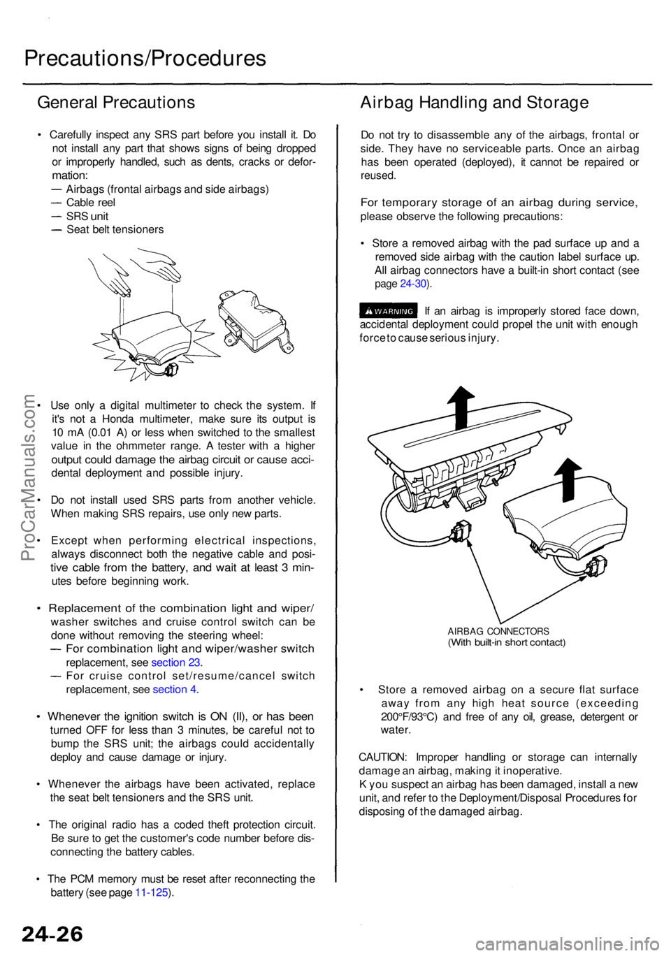
• Stor e a remove d airba g wit h th e pa d surfac e u p an d a
remove d sid e airba g wit h th e cautio n labe l surfac e up .
Al l airba g connector s hav e a built-i n shor t contac t (se e
page 24-30 ).
If a n airba g is improperl y store d fac e down ,
accidenta l deploymen t coul d prope l th e uni t wit h enoug h
forc e to caus e seriou s injury .
AIRBA G CONNECTOR S(With built-i n shor t contact )
• Stor e a remove d airba g o n a secur e fla t surfac e
awa y fro m an y hig h hea t sourc e (exceedin g
200°F/93°C ) an d fre e o f an y oil , grease , detergen t o r
water .
CAUTION : Imprope r handlin g o r storag e ca n internall y
damag e a n airbag , makin g it inoperative .
K yo u suspec t a n airba g ha s bee n damaged , instal l a ne w
unit , an d refe r t o th e Deployment/Disposa l Procedure s fo r
disposin g o f th e damage d airbag .
ProCarManuals.com
Page 1796 of 1954
Seat Bel t Tensione r Handlin g an d
Storag e
Do no t tr y t o disassembl e th e sea t bel t tensione r assem -
bly . I t ha s n o serviceabl e parts . Onc e a sea t bel t tensione r
ha s bee n activated , i t canno t b e repaire d o r reused .
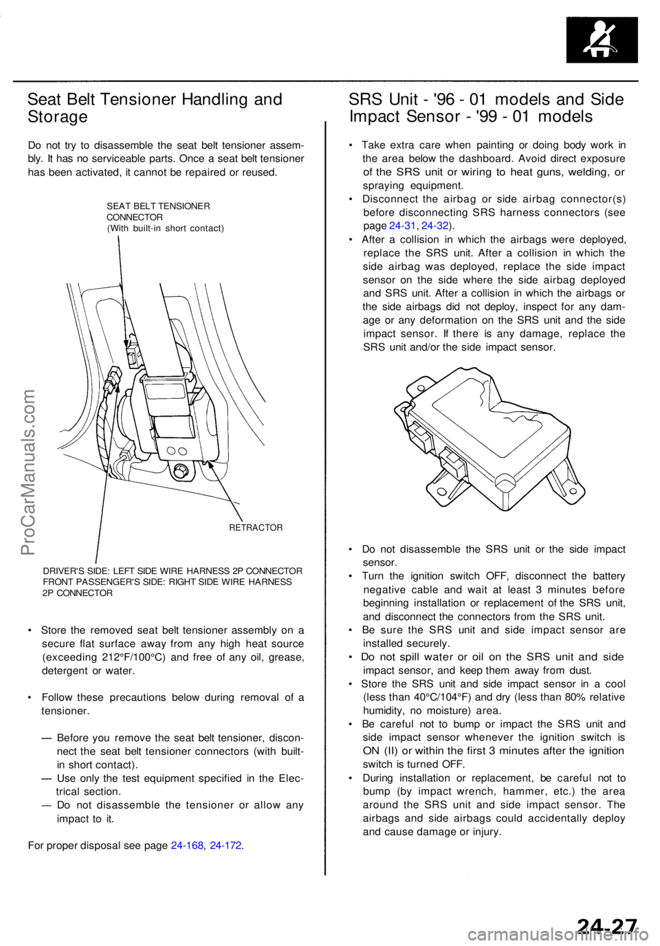
SEAT BEL T TENSIONE R
CONNECTO R
(Wit h built-i n shor t contact )
RETRACTO R
DRIVER'S SIDE : LEF T SID E WIR E HARNES S 2 P CONNECTO R
FRON T PASSENGER' S SIDE : RIGH T SID E WIR E HARNES S
2 P CONNECTO R
• Stor e th e remove d sea t bel t tensione r assembl y o n a
secur e fla t surfac e awa y fro m an y hig h hea t sourc e
(exceedin g 212°F/100°C ) an d fre e o f an y oil , grease ,
detergen t o r water .
• Follo w thes e precaution s belo w during remova l o f a
tensioner .
Befor e yo u remov e th e sea t bel t tensioner , discon -
nec t th e sea t bel t tensione r connector s (wit h built -
i n shor t contact) .
Us e onl y th e tes t equipmen t specifie d i n th e Elec -
trica l section .
D o no t disassembl e th e tensione r o r allo w an y
impac t t o it .
Fo r prope r disposa l se e pag e 24-168 , 24-172 .
SRS Uni t - '9 6 - 0 1 model s an d Sid e
Impac t Senso r - '9 9 - 0 1 model s
• Tak e extr a car e whe n paintin g o r doin g bod y wor k i n
th e are a belo w th e dashboard . Avoi d direc t exposur e
of th e SR S uni t o r wirin g t o hea t guns , welding , o r
sprayin g equipment .
• Disconnec t th e airba g o r sid e airba g connector(s )
befor e disconnectin g SR S harnes s connector s (se e
pag e 24-31 , 24-32 ).
• Afte r a collisio n i n whic h th e airbag s wer e deployed ,
replac e th e SR S unit . Afte r a collisio n i n whic h th e
sid e airba g wa s deployed , replac e th e sid e impac t
senso r o n th e sid e wher e th e sid e airba g deploye d
an d SR S unit . Afte r a collisio n i n whic h th e airbag s o r
th e sid e airbag s di d no t deploy , inspec t fo r an y dam -
ag e o r an y deformatio n o n th e SR S uni t an d th e sid e
impac t sensor . I f ther e i s an y damage , replac e th e
SR S uni t and/o r th e sid e impac t sensor .
• D o no t disassembl e th e SR S uni t o r th e sid e impac t
sensor .
• Tur n th e ignitio n switc h OFF , disconnec t th e batter y
negativ e cabl e an d wai t a t leas t 3 minute s befor e
beginnin g installatio n o r replacemen t o f th e SR S unit ,
an d disconnec t th e connector s fro m th e SR S unit .
• B e sur e th e SR S uni t an d sid e impac t senso r ar e
installe d securely .
• D o no t spil l wate r o r oi l o n th e SR S uni t an d sid e
impac t sensor , an d kee p the m awa y fro m dust .
• Stor e th e SR S uni t an d sid e impac t senso r i n a coo l
(les s tha n 40°C/104°F ) an d dr y (les s tha n 80 % relativ e
humidity , n o moisture ) area .
• B e carefu l no t t o bum p o r impac t th e SR S uni t an d
sid e impac t senso r wheneve r th e ignitio n switc h i s
ON (II ) o r withi n th e firs t 3 minute s afte r th e ignitio n
switch i s turne d OFF .
• Durin g installatio n o r replacement , b e carefu l no t t o
bum p (b y impac t wrench , hammer , etc. ) th e are a
aroun d th e SR S uni t an d sid e impac t sensor . Th e
airbag s an d sid e airbag s coul d accidentall y deplo y
an d caus e damag e o r injury .
ProCarManuals.com
Page 1797 of 1954
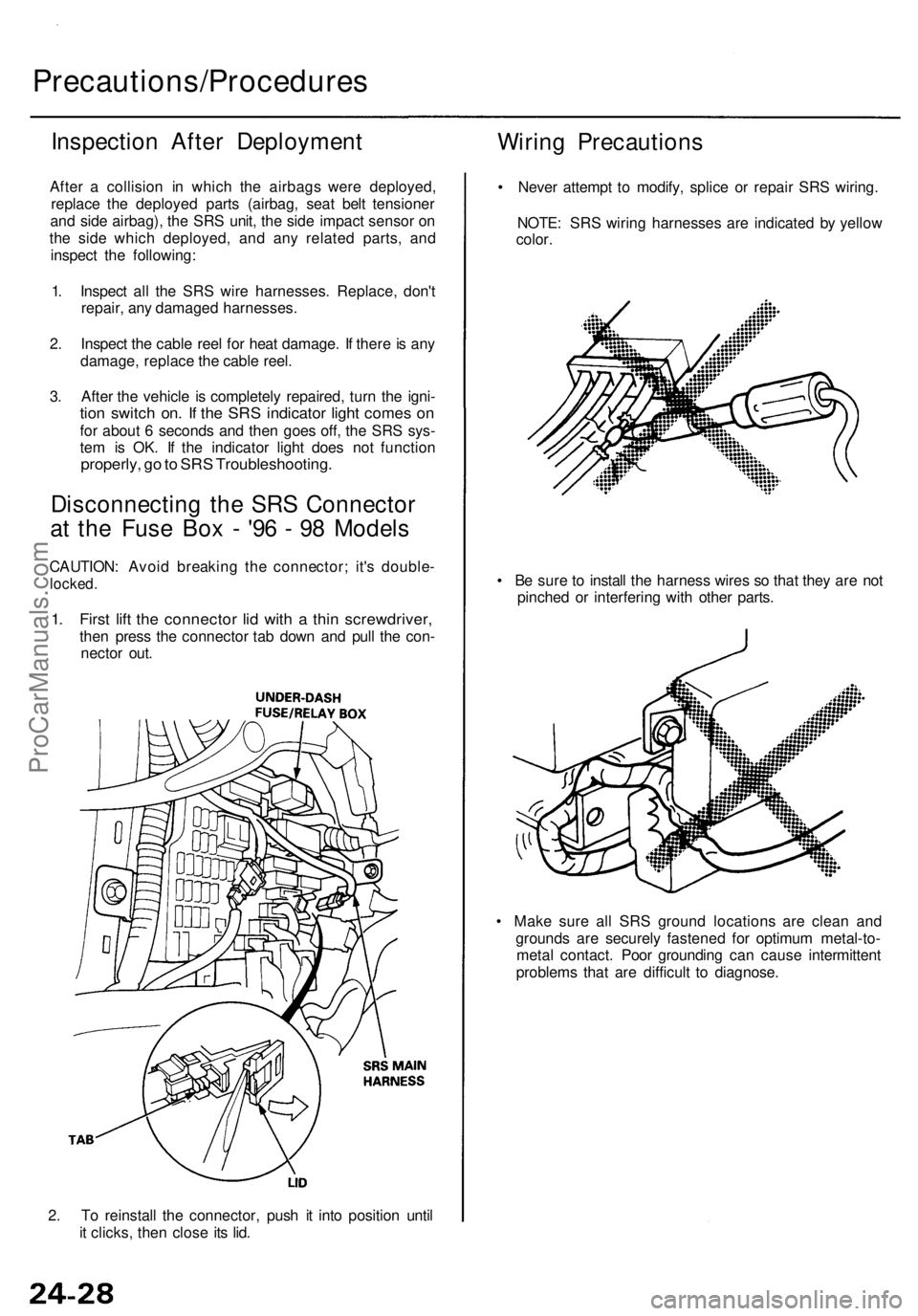
2. To reinstall the connector, push it into position until
it clicks, then close its lid.
Precautions/Procedures
Inspection After Deployment
After a collision in which the airbags were deployed,
replace the deployed parts (airbag, seat belt tensioner
and side airbag), the SRS unit, the side impact sensor on
the side which deployed, and any related parts, and
inspect the following:
1. Inspect all the SRS wire harnesses. Replace, don't
repair, any damaged harnesses.
2. Inspect the cable reel for heat damage. If there is any
damage, replace the cable reel.
3. After the vehicle is completely repaired, turn the igni-
tion switch on. If the SRS indicator light comes on
for about 6 seconds and then goes off, the SRS sys-
tem is OK. If the indicator light does not function
properly, go to SRS Troubleshooting.
Disconnecting the SRS Connector
at the Fuse Box - '96 - 98 Models
CAUTION: Avoid breaking the connector; it's double-
locked.
1. First lift the connector lid with a thin screwdriver,
then press the connector tab down and pull the con-
nector out.
Wiring Precautions
• Never attempt to modify, splice or repair SRS wiring.
NOTE: SRS wiring harnesses are indicated by yellow
color.
• Be sure to install the harness wires so that they are not
pinched or interfering with other parts.
• Make sure all SRS ground locations are clean and
grounds are securely fastened for optimum metal-to-
metal contact. Poor grounding can cause intermittent
problems that are difficult to diagnose.ProCarManuals.com