Page 1510 of 1954
Relay an d Contro l Uni t Location s
Engine Compartmen t
TCS FAIL-SAF E RELA Y('96-99 models )
• FRON T SEA T HEATE R
RELA Y ('9 8 model )
• ACCESSOR Y POWE R
SOCKE T RELA Y
('9 9-0 1 models )
UNDER-HOO D RELA Y
BOX C
RADIATO R FA NRELA Y
VSA MODULATO R UNI T('00 - 01 models )
• POWE R WINDO W
MASTE R SWITC H
RELAY('96-9 7 models )• TAILLIGH T RELA Y
('9 9-0 1 models )WINDSHIEL
D WIPE R
MOTO R RELA Y
- AB S REA R FAIL-SAF E
RELAY('96-9 7 models )• HOR N RELA Y
('9 8-0 1 models )
FRON T FO G LIGH T
RELA Y
• AB S FRON T FAIL-SAF E
RELA Y ('96-9 7 models )
• AB S FAIL-SAF E RELA Y
('98-99 models )
GAUGE RELA Y
A/ T REVERS ERELAY
REAR WINDO W
DEFOGGE R RELA Y
WINDSHIEL D WIPE R
INTERMITTEN TRELAYRADIATO R FA N
MAI N RELA Y CONDENSE
R FA NRELA YA/C COMPRESSO R
CLUTC H RELA Y
•
LO W BEA M CU T RELA Y
(Canada : '9 6 - 9 8 models )
• SECURIT Y HOR N RELA Y
(USA: '99-0 1 models )
• LO W BEA M CU T RELA Y
(Canada : '0 0-0 1 models )
UNDER-HOO D RELA Y
BOX A
ProCarManuals.com
Page 1518 of 1954
Power Relay s
Relay Tes t (cont'd )
• Starte r cu t rela y
• Blowe r moto r rela y
• Blowe r moto r hig h rela y
Headligh t lo w bea m rela y ('9 9 - 0 1 models )
Securit y hor n rela y ('9 9 - 0 1 models )
Tailligh t rela y ('9 6 - 9 8 models )
Wipe r moto r rela y
A/ C compresso r clutc h rela y
Powe r windo w rela y
Condense r fa n rela y
typ e 1 :
typ e 2 :
Normally-close d type :
1. Chec k fo r continuit y betwee n th e terminals .
• Ther e shoul d b e continuit y betwee n th e No . 1
an d No . 3 terminal s whe n powe r i s no t connecte d
t o th e No . 2 an d No . 4 terminals .
• Ther e shoul d b e n o continuit y betwee n th e No . 1
an d No . 3 terminal s whe n powe r an d groun d ar e
connecte d to th e No . 2 an d No . 4 terminals .
• Lo w bea m cu t rela y ('9 6 - 9 8 Canad a models )
ProCarManuals.com
Page 1575 of 1954
Horns
Componen t Locatio n Inde x
SRS component s ar e locate d i n thi s area . Revie w th e SR S componen t locations , precautions , an d procedure s i n th e SR S
( sectio n 24 ) befor e performin g repair s o r service .
CABLE REE LSee sectio n 2 4
UNDER-HOO
D
RELAY BO X B
Wir e colors : WHT/YEL , OR N
BLU/RE D an d WHT/YE L
Test , pag e 23-6 7
HOR
N RELAY*
1
• HOR N ('9 6 - 9 8 models )Test, pag e 23-161• SECURIT Y
HOR N ('9 9 - 0 1 models )
Test , pag e 23-161
HORN S
Test , pag e 23-161
SECURITY HOR N RELA Y
('9 9 - 0 1 models )
Test , pag e 23-6 8
Wir
e colors : WHT/YEL , BLU/OR N
BLU/RE D an d WHT/YE L
Test , pag e 23-6 9
HOR N RELAY*2
HOR N SWITC H
Test , pag e 23-162
*1: '9 6 - 9 7 model s*2:'98-01 model s
ProCarManuals.com
Page 1576 of 1954
2. Remov e th e horns .
RIGHT HOR N o r SECURIT Y
HOR N
CONNECTO R
CONNECTO R
Horn Tes t
1. Disconnec t th e 2 P (o r 1P ) connector s fro m th e
horns .
LEFT HOR N
3. Tes t th e hor n b y connectin g batter y powe r t o on e
termina l an d groundin g th e other . Th e hor n shoul d
sound .
4 . I f th e hor n fail s t o work , replac e it .
No . 2 (Ground )
No. 1
No . 1
No . 2
ProCarManuals.com
Page 1645 of 1954

System Function s
• Multiple x Contro l Syste m (Multiple x function , Wak e up/slee p function , Fail-saf e function , Self-diagnosi s function* )
* : Self-diagnosi s functio n mod e 1 is th e self-diagnosi s fo r th e multiple x contro l system .
Self-diagnosi s functio n mod e 2 is th e failur e diagnosi s fo r th e inpu t lin e o f eac h system .
• Integrate d Contro l Syste m (Engin e oi l pressur e indicato r flashe r circuit , Key-i n reminde r circuit , Light-o n reminde r circuit ,
Sea t bel t reminde r circuit )
• Das h Light s Brightnes s Contro l
• Entr y Ligh t Contro l Syste m
• Rea r Windo w Defogge r
• Trun k li d Opene r
• Powe r Doo r Lock s (wit h keyles s entr y system )
• Powe r Windo w (wit h key-of f timer operation )
• Wiper/washer s (wit h spee d responden t intermitten t wiper )
• Securit y Alar m Syste m
• Interloc k Syste m (se e sectio n 14 )
Multiple x Communicatio n Syste m
Multiple x Communicatio n Function s
• T o reduc e th e numbe r o f wir e harnesses , digita l signal s ar e sen t vi a share d multiple x communicatio n line s rather than
sendin g norma l electrica l signal s throug h individua l wires .
• Th e inpu t signal s fro m eac h switc h ar e converte d t o digita l signal s a t th e centra l processin g uni t (CPU) . Th e digita l
signal s ar e sen t fro m th e transmitte r uni t t o th e receive r uni t a s seria l signals .
• Th e transmitte d signa l i s converte d t o a switc h signa l a t th e receive r unit , an d it operate s th e relate d component .
• Ther e ar e exclusiv e communicatio n line s betwee n eac h o f th e multiple x contro l units :
Door Driver' s (fro m th e doo r t o th e driver' s multiple x contro l units ) Wir e color : BRN/YE L
Driver's Passenger' s (fro m th e driver' s t o th e passenger' s multiple x contro l units ) Wir e color : BRN/WH T
Passenger' s Driver' s (fro m th e passenger' s t o th e driver' s multiple x contro l units ) Wir e color : RED/YE L
• Th e contro l unit s alway s communicat e vi a thes e line s whe n th e syste m is operating , an d the y sto p communicatin g
whe n th e syste m is OFF .
Wake-u p an d Slee p Function s
• Th e multiple x contro l syste m ha s "wake-up " an d "sleep " function s t o decreas e parasiti c dra w o n th e batter y whe n th e
ignitio n switc h is OFF .
• I n th e slee p mode , th e multiple x contro l uni t stop s th e function s (communicatio n an d CP U control ) whe n i t i s no t nec -
essar y fo r th e syste m to operate .
• A s soo n a s an y operatio n i s don e (fo r example , a doo r i s unlocked) , th e relate d contro l uni t i n th e slee p mod e wake s u p
an d begin s t o functio n a t once . Thi s contro l uni t als o send s a wake-u p signa l t o th e othe r contro l unit s vi a th e commu -
nicatio n lines .
• Whe n th e ignitio n switc h i s turne d OFF , ther e i s abou t a 30 secon d dela y befor e th e contro l unit s g o fro m th e wake-u p
mod e t o th e slee p mode .
• I f an y doo r i s open , th e slee p mod e wil l no t function .
Fail-safe Function s
• T o preven t imprope r operation , th e multiple x contro l syste m ha s a fail-saf e function . I n th e fail-saf e mode , th e outpu t
signa l i s fixe d whe n an y par t o f th e syste m malfunction s (fo r example , a fault y contro l uni t o r communicatio n line) .
• Eac h contro l uni t ha s a hardwar e fail-saf e functio n tha t fixe s th e outpu t signa l whe n ther e i s an y CP U malfunctio n an d
a softwar e fail-saf e functio n tha t ignore s th e signa l fro m th e malfunctionin g contro l uni t an d allow s th e syste m to
operat e normally .
ProCarManuals.com
Page 1656 of 1954

Multiplex Contro l Syste m
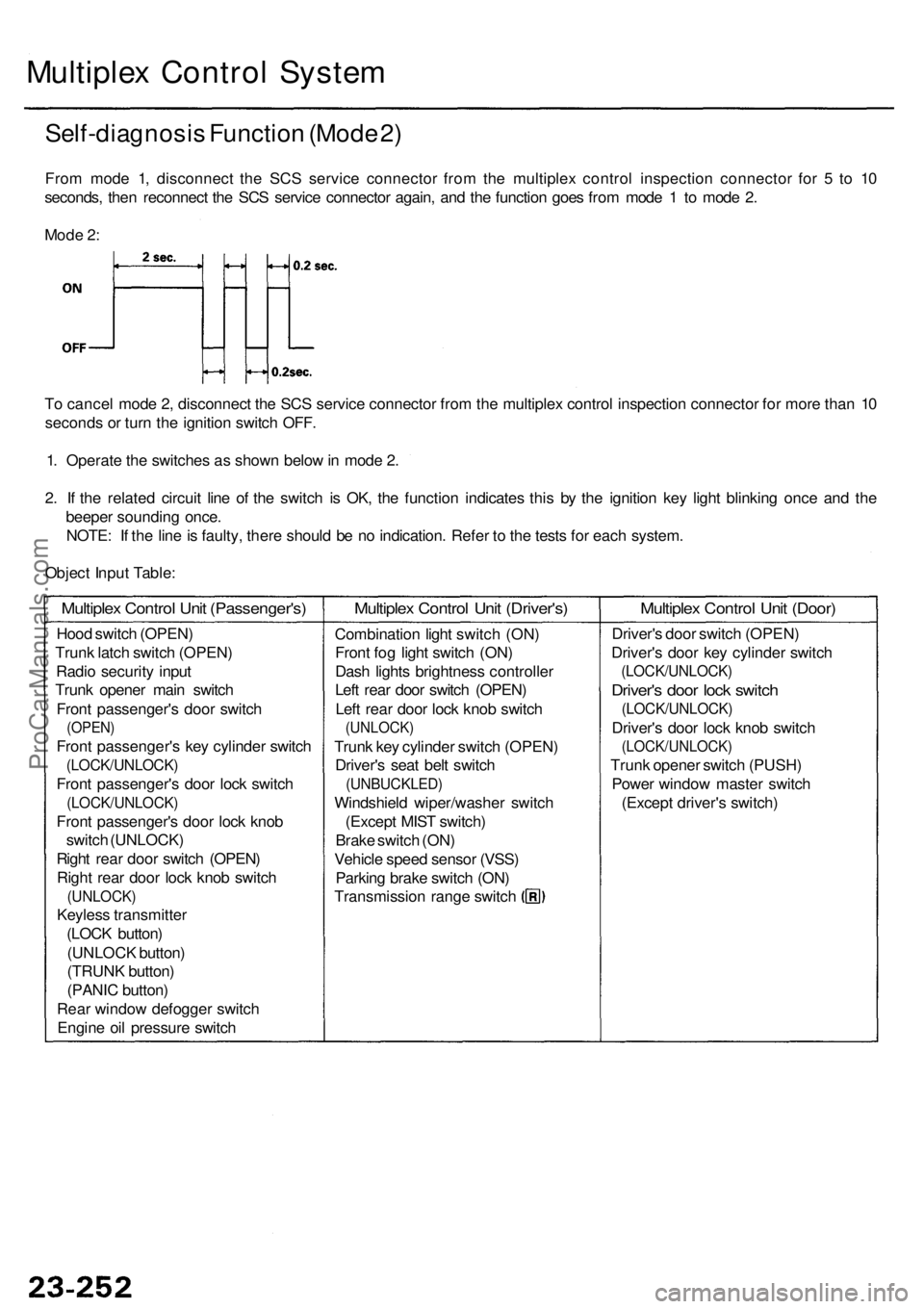
Self-diagnosi s Functio n (Mod e 2 )
Fro m mod e 1 , disconnec t th e SC S servic e connecto r fro m th e multiple x contro l inspectio n connecto r fo r 5 to 1 0
seconds , the n reconnec t th e SC S servic e connecto r again , an d th e functio n goe s fro m mod e 1 to mod e 2 .
T o cance l mod e 2 , disconnec t th e SC S servic e connecto r fro m th e multiple x contro l inspectio n connecto r fo r mor e tha n 1 0
second s o r tur n th e ignitio n switc h OFF .
1 . Operat e th e switche s a s show n belo w in mod e 2 .
2 . I f th e relate d circui t lin e o f th e switc h i s OK , th e functio n indicate s thi s b y th e ignitio n ke y ligh t blinkin g onc e an d th e
beepe r soundin g once .
NOTE : I f th e lin e is faulty , ther e shoul d b e n o indication . Refe r t o th e test s fo r eac h system .
Objec t Inpu t Table :
Mod
e 2 :
Hoo d switc h (OPEN )
Trun k latc h switc h (OPEN )
Radi o securit y inpu t
Trun k opene r mai n switc h
Fron t passenger' s doo r switc h
(OPEN )
Front passenger' s ke y cylinde r switc h
(LOCK/UNLOCK )
Front passenger' s doo r loc k switc h
(LOCK/UNLOCK )
Front passenger' s doo r loc k kno b
switc h (UNLOCK )
Righ t rea r doo r switc h (OPEN )
Righ t rea r doo r loc k kno b switc h
(UNLOCK )
Keyless transmitte r
(LOC K button )
(UNLOC K button )
(TRUN K button )
(PANI C button )
Rea r windo w defogge r switc h
Engin e oi l pressur e switc h
Multiple x Contro l Uni t (Passenger's )Multiplex Contro l Uni t (Driver's )
Combinatio n ligh t switc h (ON )
Fron t fo g ligh t switc h (ON )
Das h light s brightnes s controlle r
Lef t rea r doo r switc h (OPEN )
Lef t rea r doo r loc k kno b switc h
(UNLOCK )
Trunk ke y cylinde r switc h (OPEN )
Driver' s sea t bel t switc h
(UNBUCKLED )
Windshield wiper/washe r switc h
(Excep t MIS T switch )
Brak e switc h (ON )
Vehicl e spee d senso r (VSS )
Parkin g brak e switc h (ON )
Transmissio n rang e switc h
Multiple x Contro l Uni t (Door )
Driver' s doo r switc h (OPEN )
Driver' s doo r ke y cylinde r switc h
(LOCK/UNLOCK )
Driver's doo r loc k switc h
(LOCK/UNLOCK )
Driver's doo r loc k kno b switc h
(LOCK/UNLOCK )
Trunk opene r switc h (PUSH )
Powe r windo w maste r switc h
(Excep t driver' s switch )
ProCarManuals.com
Page 1709 of 1954

Security Alar m Syste m
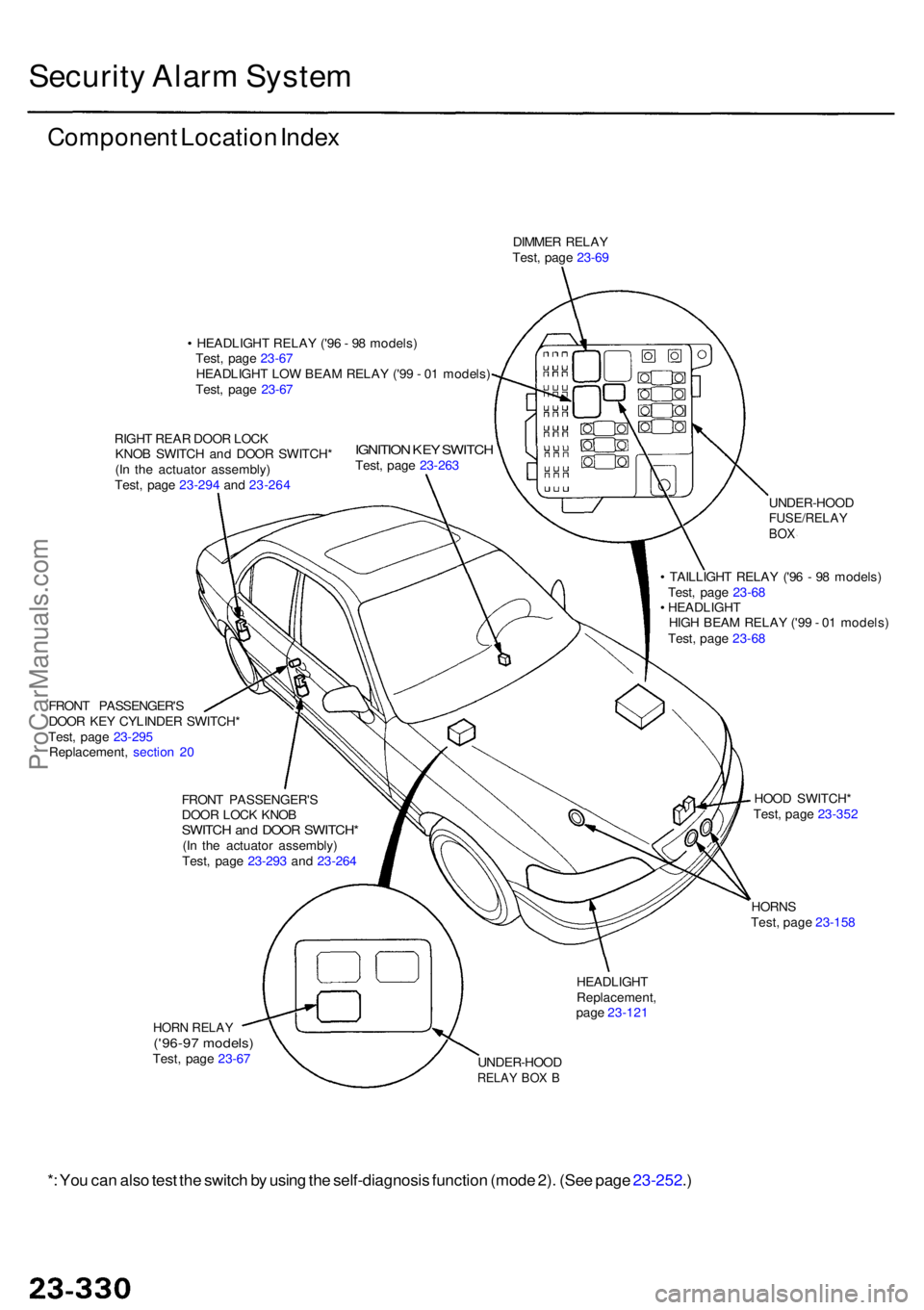
Componen t Locatio n Inde x
DIMME R RELA Y
Test , pag e 23-6 9
• HEADLIGH T RELA Y ('9 6 - 9 8 models )
Test , pag e 23-6 7
HEADLIGH T LO W BEA M RELA Y ('9 9 - 0 1 models )
Test , pag e 23-6 7
RIGH T REA R DOO R LOC K
KNO B SWITC H an d DOO R SWITCH *
(I n th e actuato r assembly )
Test , pag e 23-29 4 an d 23-26 4
IGNITIO N KE Y SWITC HTest, pag e 23-26 3
FRON T PASSENGER' S
DOO R KE Y CYLINDE R SWITCH *
Test , pag e 23-29 5
Replacement , sectio n 2 0
FRON T PASSENGER' S
DOO R LOC K KNO B
SWITC H an d DOO R SWITCH *(In th e actuato r assembly )
Test , pag e 23-29 3 an d 23-26 4 UNDER-HOO
D
FUSE/RELAYBOX
• TAILLIGH T RELA Y ('9 6 - 9 8 models )
Test , pag e 23-6 8
• HEADLIGH T
HIG H BEA M RELA Y ('9 9 - 0 1 models )
Test , pag e 23-6 8
HOO D SWITCH *
Test , pag e 23-35 2
HORN S
Test , pag e 23-15 8
HEADLIGH TReplacement ,
pag e 23-12 1
UNDER-HOO D
RELAY BO X B
HOR N RELA Y('96-97 models )Test, pag e 23-6 7
*: Yo u ca n als o tes t th e switc h b y usin g th e self-diagnosi s functio n (mod e 2) . (Se e pag e 23-252 .)
ProCarManuals.com
Page 1710 of 1954

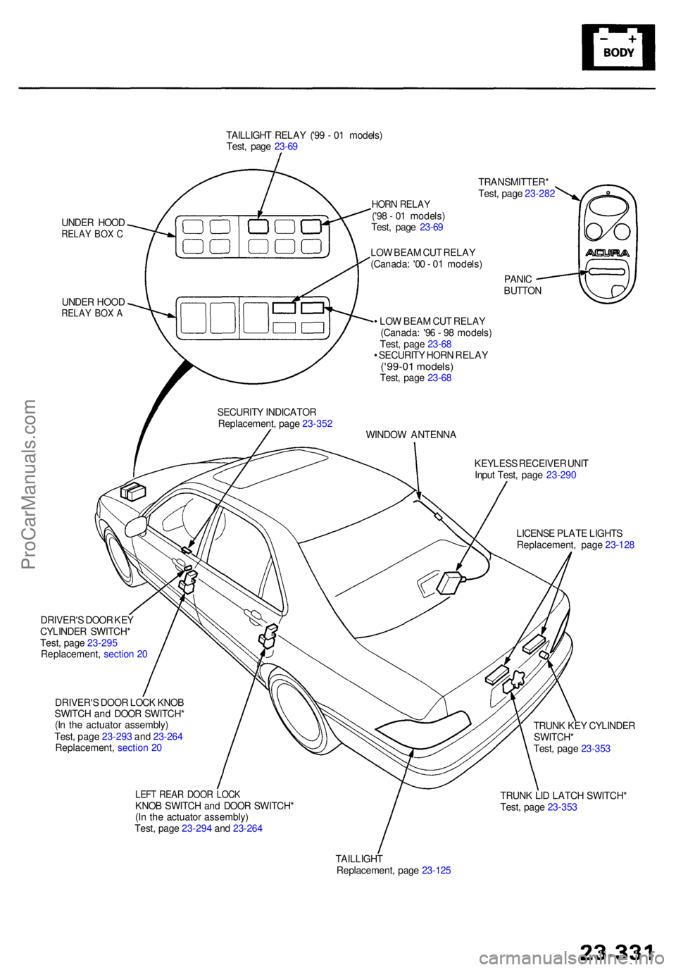
TAILLIGHT RELA Y ('9 9 - 0 1 models )
Test , pag e 23-6 9
UNDE R HOO D
RELA Y BO X C
UNDE R HOO DRELA Y BO X A
HOR N RELA Y('98 - 0 1 models )
Test , pag e 23-6 9 TRANSMITTER
*
Test , pag e 23-28 2
PANI C
BUTTO N
LO
W BEA M CU T RELA Y
(Canada : '0 0 - 0 1 models )
• LO W BEA M CU T RELA Y
(Canada : '9 6 - 9 8 models )
Test , pag e 23-6 8
• SECURIT Y HOR N RELA Y
('99-01 models )Test, pag e 23-6 8
WINDO W ANTENN A
KEYLES S RECEIVE R UNI T
Inpu t Test , pag e 23-29 0
LICENS E PLAT E LIGHT S
Replacement , pag e 23-12 8
SECURIT
Y INDICATO R
Replacement , pag e 23-35 2
TRUNK KE Y CYLINDE R
SWITCH *
Test , pag e 23-35 3
TRUN K LI D LATC H SWITCH *
Test , pag e 23-35 3
TAILLIGH T
Replacement , pag e 23-12 5
LEFT REA R DOO R LOC KKNOB SWITC H an d DOO R SWITCH *
(I n th e actuato r assembly )
Test , pag e 23-29 4 an d 23-26 4
DRIVER'
S DOO R LOC K KNO B
SWITC H an d DOO R SWITCH *
(I n th e actuato r assembly )
Test , pag e 23-29 3 an d 23-26 4
Replacement , sectio n 2 0
DRIVER'
S DOO R KE Y
CYLINDE R SWITCH *
Test , pag e 23-29 5
Replacement , sectio n 2 0
ProCarManuals.com