1996 ACURA RL KA9 ECU
[x] Cancel search: ECUPage 1033 of 1954
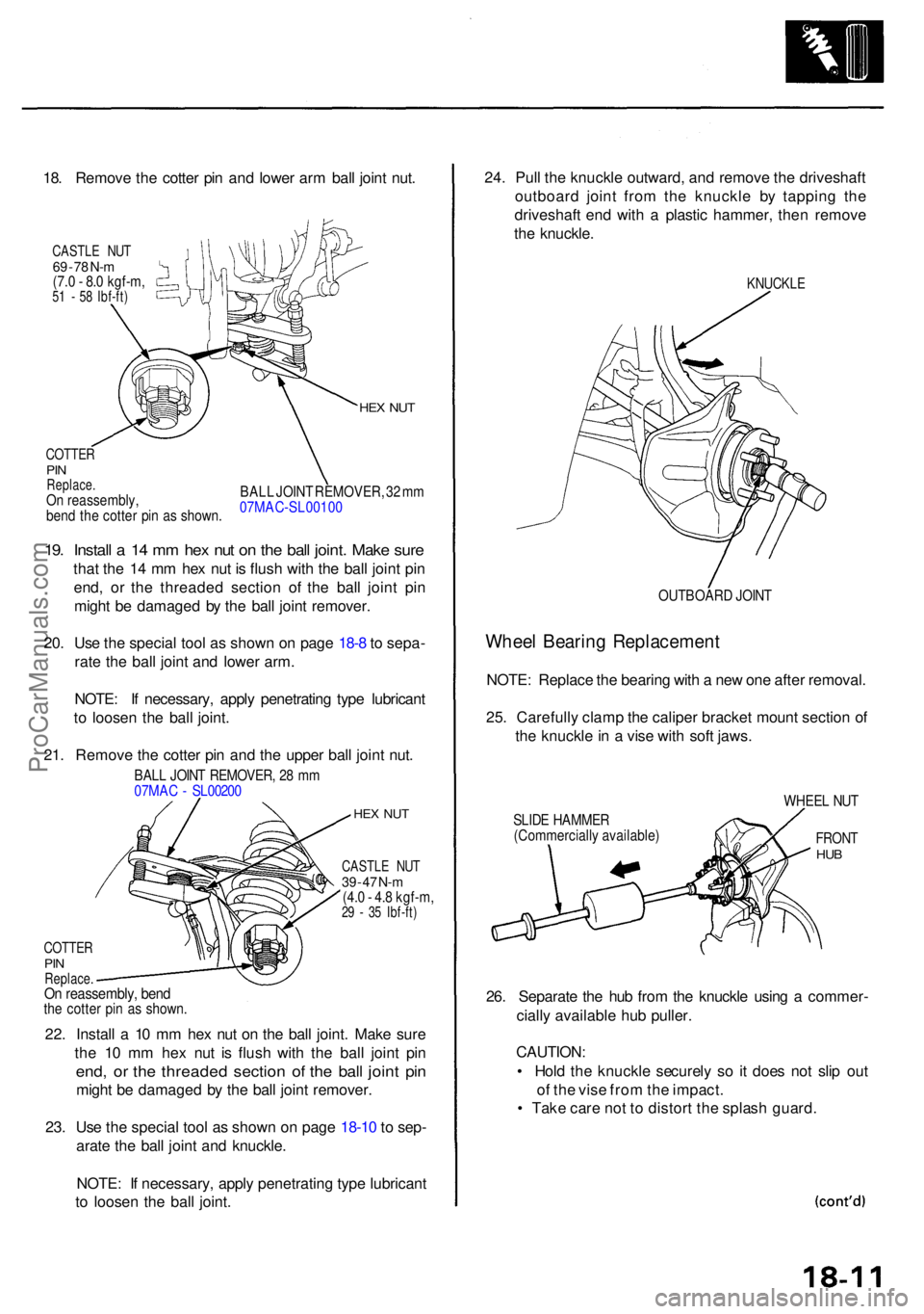
18. Remov e th e cotte r pi n an d lowe r ar m bal l join t nut .
CASTL E NU T69 - 7 8 N- m(7. 0 - 8. 0 kgf-m ,51 - 5 8 Ibf-ft )
COTTE RPINReplace .On reassembly ,
ben d th e cotte r pi n a s shown .
HEX NU T
BAL L JOIN T REMOVER , 3 2 m m
07MAC-SL0010 0
19. Instal l a 14 m m he x nu t o n th e bal l joint . Mak e sur e
that th e 1 4 m m he x nu t i s flus h wit h th e bal l join t pi n
end , o r th e threade d sectio n of the bal l join t pi n
migh t b e damage d b y th e bal l join t remover .
20 . Us e th e specia l too l a s show n o n pag e 18- 8 to sepa -
rat e th e bal l join t an d lowe r arm .
NOTE : I f necessary , appl y penetratin g typ e lubrican t
t o loose n th e bal l joint .
21 . Remov e th e cotte r pi n an d th e uppe r bal l join t nut .
BAL L JOIN T REMOVER , 2 8 m m
07MA C - SL0020 0
HEX NU T
24. Pul l th e knuckl e outward , an d remov e th e driveshaf t
outboar d join t fro m th e knuckl e b y tappin g th e
driveshaf t en d wit h a plasti c hammer , the n remov e
th e knuckle .
KNUCKL E
OUTBOAR D JOIN T
Whee l Bearin g Replacemen t
NOTE: Replac e th e bearin g wit h a ne w on e afte r removal .
25 . Carefull y clam p th e calipe r bracke t moun t sectio n o f
th e knuckl e in a vis e wit h sof t jaws .
SLIDE HAMME R
(Commerciall y available ) WHEE
L NU T
FRON THUB
26. Separat e th e hu b fro m th e knuckl e usin g a commer -
ciall y availabl e hu b puller .
CAUTION :
• Hol d th e knuckl e securel y s o it doe s no t sli p ou t
o f th e vis e fro m th e impact .
• Tak e car e no t t o distor t th e splas h guard .
22
. Instal l a 10 m m he x nu t o n th e bal l joint . Mak e sur e
th e 1 0 m m he x nu t i s flus h wit h th e bal l join t pi n
end , o r th e threade d sectio n o f th e bal l join t pi n
migh t b e damage d b y th e bal l join t remover .
23 . Us e th e specia l too l a s show n o n pag e 18-1 0 to sep -
arat e th e bal l join t an d knuckle .
NOTE : I f necessary , appl y penetratin g typ e lubrican t
t o loose n th e bal l joint .
COTTE RPINReplace .On reassembly , ben dthe cotte r pi n a s shown .
CASTL E NU T39 - 4 7 N- m(4. 0 - 4. 8 kgf-m ,29 - 3 5 Ibf-ft )
ProCarManuals.com
Page 1035 of 1954
NOTE: Was h th e knuckl e an d hu b thoroughl y i n
hig h flas h poin t solven t befor e reassembly .
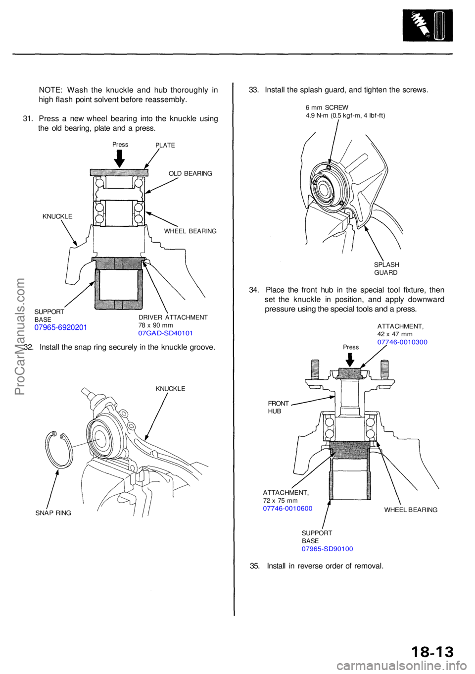
31 . Pres s a ne w whee l bearin g int o th e knuckl e usin g
th e ol d bearing , plat e an d a press .
PressPLAT E
OLD BEARIN G
KNUCKL E
SUPPOR TBASE07965-6920201
WHEE L BEARIN G
DRIVER ATTACHMEN T78 x 90 m m07GAD-SD4010 1
32. Instal l th e sna p rin g securel y in th e knuckl e groove .
KNUCKL E
SNAP RIN G
33. Instal l th e splas h guard , an d tighte n th e screws .
6 m m SCRE W
4. 9 N- m (0. 5 kgf-m , 4 Ibf-ft )
SPLAS H
GUARD
34. Plac e th e fron t hu b i n th e specia l too l fixture , the n
se t th e knuckl e i n position , an d appl y downwar d
pressure usin g th e specia l tool s an d a press .
Press
ATTACHMENT ,42 x 47 m m07746-001030 0
FRONTHUB
ATTACHMENT ,72 x 7 5 m m07746-001060 0WHEEL BEARIN G
SUPPOR TBASE07965-SD9010 0
35. Instal l i n revers e orde r o f removal .
ProCarManuals.com
Page 1036 of 1954
Front Suspensio n
Ball Join t Boo t Replacemen t
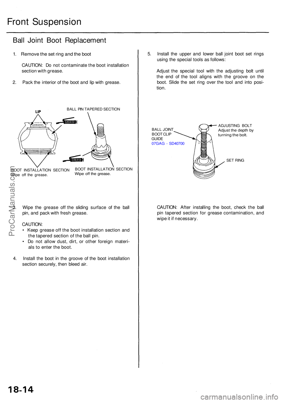
1. Remov e th e se t rin g an d th e boo t
CAUTION : D o no t contaminat e th e boo t installatio n
sectio n wit h grease .
2 . Pac k th e interio r o f th e boo t an d li p wit h grease .
BALL PI N TAPERE D SECTIO N
3. Wip e th e greas e of f th e slidin g surfac e o f th e bal l
pin , an d pac k wit h fres h grease .
CAUTION :
• Kee p greas e of f th e boo t installatio n sectio n an d
th e tapere d sectio n o f th e bal l pin .
• D o no t allo w dust , dirt , o r othe r foreig n materi -
al s to ente r th e boot .
4 . Instal l th e boo t i n th e groov e o f th e boo t installatio n
sectio n securely , the n blee d air . 5
. Instal l th e uppe r an d lowe r bal l join t boo t se t ring s
usin g th e specia l tool s a s follows :
Adjus t th e specia l too l wit h th e adjustin g bol t unti l
th e en d o f th e too l align s wit h th e groov e o n th e
boot . Slid e th e se t rin g ove r th e too l an d int o posi -
tion.
BAL L JOIN T
BOO T CLI P
GUID E
07GA G - SD4070 0 ADJUSTIN
G BOL TAdjust th e dept h b yturnin g th e bolt .
SET RIN G
CAUTION : Afte r installin g th e boot , chec k th e bal l
pi n tapere d sectio n fo r greas e contamination , an d
wip e it i f necessary .
BOOT INSTALLATIO N SECTIO N
Wip e of f th e grease . BOO
T INSTALLATIO N SECTIO NWipe of f th e grease .
ProCarManuals.com
Page 1040 of 1954
Front Dampe r
Reassembl y
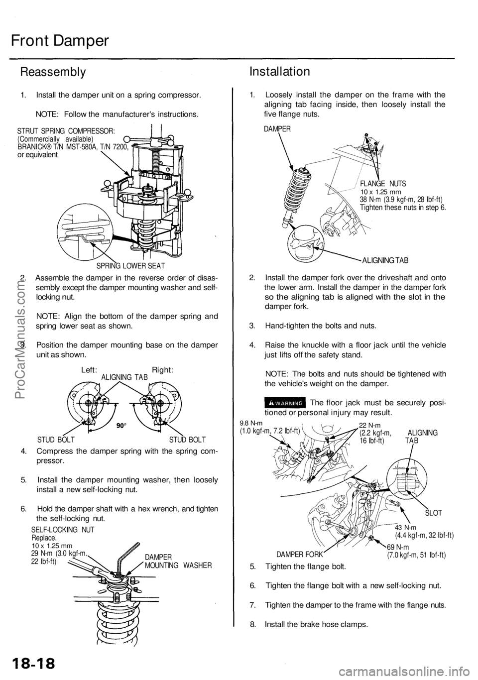
1. Instal l th e dampe r uni t o n a sprin g compressor .
NOTE : Follo w th e manufacturer' s instructions .
STRUT SPRIN G COMPRESSOR :
(Commerciall y available )
BRANICK ® T/ N MST-580A , T/ N 7200 ,
or equivalen t
SPRING LOWE R SEA T
2. Assembl e th e dampe r i n th e revers e orde r o f disas -
sembl y excep t th e dampe r mountin g washe r an d self -
lockin g nut .
NOTE : Alig n th e botto m o f th e damper spring an d
sprin g lowe r sea t a s shown .
3 . Positio n th e dampe r mountin g bas e o n th e dampe r
unit a s shown .
Left: Right :ALIGNING TA B
STU D BOL T STU D BOL T
4. Compres s th e dampe r sprin g wit h th e sprin g com -
pressor .
5. Instal l th e dampe r mountin g washer , the n loosel y
instal l a ne w self-lockin g nut .
6 . Hol d th e dampe r shaf t wit h a he x wrench , an d tighte n
th e self-lockin g nut .
SELF-LOCKIN G NU T
Replace .
10 x 1.2 5 mm29 N- m (3. 0 kgf-m .
2 2 Ibf-ft ) DAMPE
R
MOUNTIN G WASHE R
Installation
1. Loosel y instal l th e dampe r o n th e fram e wit h th e
alignin g ta b facin g inside , the n loosel y instal l th e
fiv e flang e nuts .
DAMPE R
FLANGE NUT S
10 x 1.2 5 mm38 N- m (3. 9 kgf-m , 2 8 Ibf-ft )Tighte n thes e nut s in ste p 6 .
ALIGNIN G TAB
2. Instal l th e dampe r for k ove r th e driveshaf t an d ont o
th e lowe r arm . Instal l th e dampe r i n th e dampe r for k
so th e alignin g ta b is aligne d wit h th e slo t i n th e
dampe r fork .
3 . Hand-tighte n th e bolt s an d nuts .
4 . Rais e th e knuckl e wit h a floo r jac k unti l th e vehicl e
jus t lift s of f th e safet y stand .
NOTE : Th e bolt s an d nut s shoul d b e tightene d wit h
th e vehicle' s weigh t o n th e damper .
Th e floo r jac k mus t b e securel y posi -
tione d o r persona l injur y ma y result .
22 N- m(2.2 kgf-m , ALIGNIN G
1 6 Ibf-ft ) TA B
9.8 N- m(1.0 kgf-m , 7. 2 Ibf-ft )
DAMPE R FOR K
5. Tighte n th e flang e bolt .
SLO T
43 N- m(4.4 kgf-m , 3 2 Ibf-ft )
69 N- m(7.0 kgf-m , 5 1 Ibf-ft )
6. Tighte n th e flang e bol t wit h a ne w self-lockin g nut .
7 . Tighte n th e dampe r t o th e fram e wit h th e flang e nuts .
8 . Instal l th e brak e hos e clamps .
ProCarManuals.com
Page 1045 of 1954
Rear Dampe r
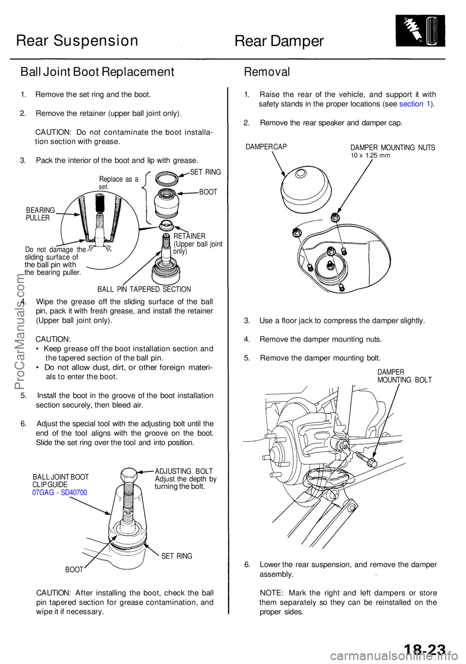
Do no t damag e th eslidin g surfac e o fthe bal l pi n wit hthe bearin g puller .
RETAINE R(Upper bal l join tonly)
BAL L PI N TAPERE D SECTIO N
4. Wip e th e greas e of f th e slidin g surfac e o f th e bal l
pin , pac k i t wit h fres h grease , an d instal l th e retaine r
(Uppe r bal l join t only) .
CAUTION :
• Kee p greas e of f th e boo t installatio n sectio n an d
th e tapere d sectio n o f th e bal l pin .
• D o no t allo w dust , dirt , o r othe r foreig n materi -
als to ente r th e boot .
5 . Instal l th e boo t i n th e groov e o f th e boo t installatio n
sectio n securely , the n blee d air .
6 . Adjus t th e specia l too l wit h th e adjustin g bol t unti l th e
en d o f th e too l align s wit h th e groov e o n th e boot .
Slid e th e se t rin g ove r th e too l an d int o position .
BALL JOIN T BOO T
CLI P GUID E
07GA G - SD4070 0 ADJUSTIN
G BOL TAdjust th e dept h b yturnin g th e bolt .
SET RIN G
BOO T
CAUTION : Afte r installin g th e boot , chec k th e bal l
pi n tapere d sectio n fo r greas e contamination , an d
wip e it i f necessary .
Removal
1. Rais e th e rea r o f th e vehicle , an d suppor t i t wit h
safet y stand s in th e prope r location s (se e sectio n 1 ).
2 . Remov e th e rea r speake r an d dampe r cap .
DAMPE R CA P
DAMPER MOUNTIN G NUT S10 x 1.2 5 mm
3. Us e a floo r jac k t o compres s th e dampe r slightly .
4 . Remov e th e dampe r mountin g nuts .
5 . Remov e th e dampe r mountin g bolt .
DAMPE RMOUNTIN G BOL T
6. Lowe r th e rea r suspension , an d remov e th e dampe r
assembly .
NOTE : Mar k th e righ t an d lef t damper s o r stor e
the m separatel y s o the y can be reinstalle d o n th e
prope r sides .
SET RIN G
BOO T
Ball Join t Boo t Replacemen t
1. Remov e th e se t rin g an d th e boot .
2 . Remov e th e retaine r (uppe r bal l join t only) .
CAUTION : D o no t contaminat e th e boo t installa -
tio n sectio n wit h grease .
3 . Pac k th e interio r o f th e boo t an d li p wit h grease .
Replace a s aset .
BEARIN GPULLER
Rear Suspension
ProCarManuals.com
Page 1054 of 1954
Inspection and Adjustment
Bleeding
CAUTION:
• Always use Genuine Honda DOT 3 Brake Fluid. Using
a non-Honda brake fluid can cause corrosion and
decrease the life of the system.
• Make sure no dirt or other foreign matter is allowed
to contaminate the brake fluid.
• Do not spill brake fluid on the vehicle, it may damage
the paint; if brake fluid does contact the paint, wash
it off immediately with water.
NOTE: The reservoir on the master cylinder must be at
the MAX (upper) level mark at the start of the bleeding
procedure and checked after bleeding each brake
caliper. Add fluid as required.
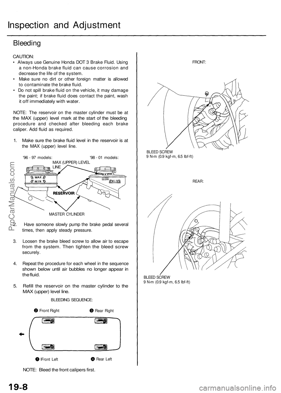
1. Make sure the brake fluid level in the reservoir is at
the MAX (upper) level line.
'96 - 97 models: '98 - 01 models:
MAX (UPPER) LEVEL
LINE
MASTER CYLINDER
2. Have someone slowly pump the brake pedal several
times, then apply steady pressure.
3. Loosen the brake bleed screw to allow air to escape
from the system. Then tighten the bleed screw
securely.
4. Repeat the procedure for each wheel in the sequence
shown below until air bubbles no longer appear in
the fluid.
5. Refill the reservoir on the master cylinder to the
MAX (upper) level line.
BLEEDING SEQUENCE:
NOTE: Bleed the front calipers first.
FRONT:
BLEED SCREW
9 N-m (0.9 kgf-m, 6.5 Ibf-ft)
REAR:
BLEED SCREW
9 N-m (0.9 kgf-m, 6.5 Ibf-ft)
Front Right
Rear Right
Rear Left
Front LeftProCarManuals.com
Page 1058 of 1954
Front Brak e Dis c
Disc Runou t Inspectio n
1. Loose n th e fron t whee l nut s slightly , the n rais e th e
vehicle , an d mak e sur e i t i s securel y supported .
Remov e th e fron t wheels .
2 . Remov e th e brak e pad s (se e pag e 19-10 ).
3 .
4 .
5 .
Inspec t th e dis c surfac e fo r damag e an d cracks .
Clean th e dis c thoroughly , an d remov e al l rust .
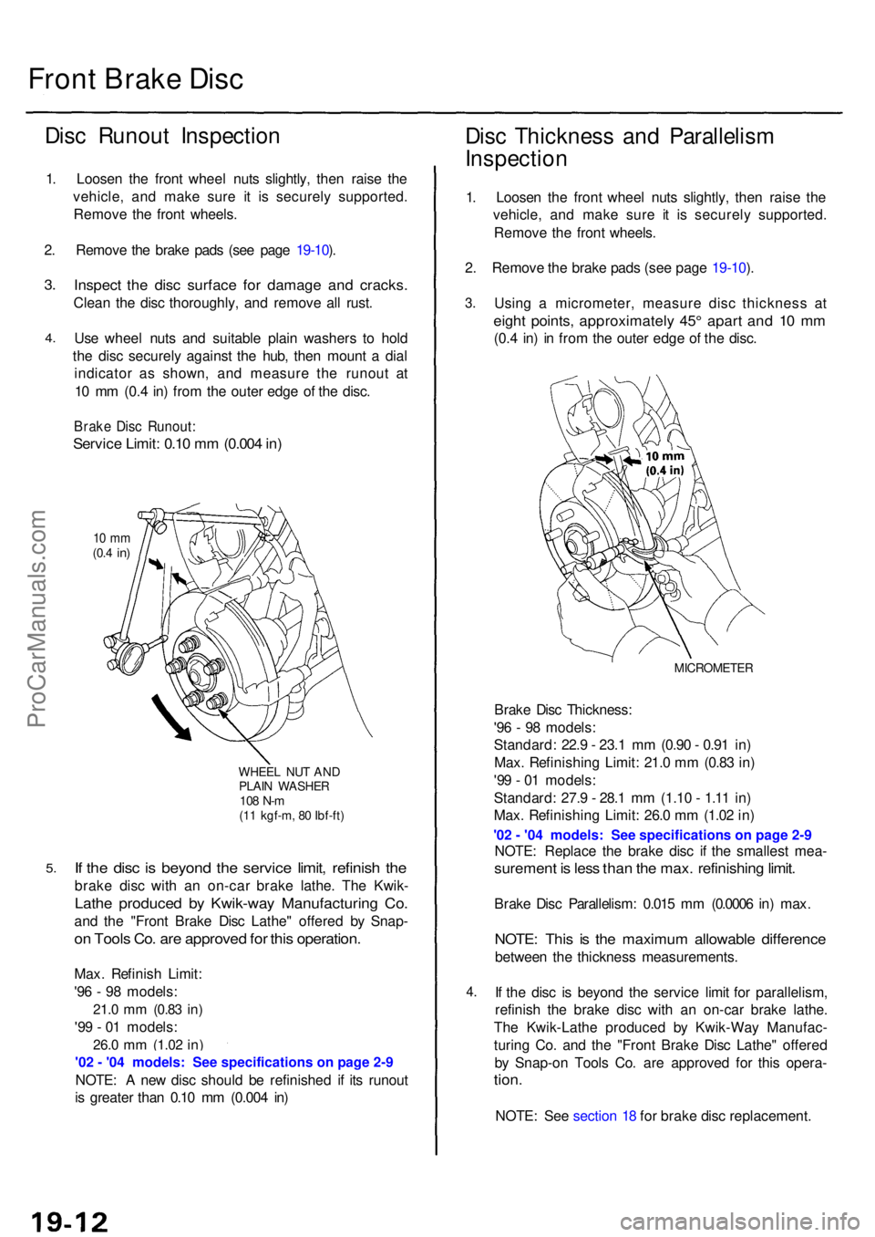
Us e whee l nut s an d suitabl e plai n washer s t o hol d
th e dis c securel y agains t th e hub , the n moun t a dia l
indicato r a s shown , an d measur e th e runou t a t
1 0 m m (0. 4 in ) fro m th e oute r edg e o f th e disc .
Brak e Dis c Runout :
Service Limit : 0.1 0 m m (0.00 4 in )
10 m m(0.4 in )
WHEE L NU T AN DPLAI N WASHE R108 N- m(11 kgf-m , 8 0 Ibf-ft )
If th e dis c i s beyon d th e servic e limit , refinis h th e
brak e dis c wit h a n on-ca r brak e lathe . Th e Kwik -
Lathe produce d b y Kwik-wa y Manufacturin g Co .
and th e "Fron t Brak e Dis c Lathe " offere d b y Snap -
on Tool s Co . ar e approve d fo r thi s operation .
Max. Refinis h Limit :
'9 6 - 9 8 models :
21.0 mm (0.8 3 in)
'99 - 0 1 models :
26.0 mm (1.0 2 in)
NOTE : A ne w dis c shoul d b e refinishe d i f it s runou t
i s greate r tha n 0.1 0 m m (0.00 4 in )
Dis c Thicknes s an d Parallelis m
Inspectio n
1. Loose n th e fron t whee l nut s slightly , the n rais e th e
vehicle , an d mak e sur e i t i s securel y supported .
Remov e th e fron t wheels .
2 . Remov e th e brak e pad s (se e pag e 19-10 ).
3 .
4.
Usin g a micrometer , measur e dis c thicknes s a t
eigh t points , approximatel y 45 ° apar t an d 1 0 m m
(0.4 in ) i n fro m th e oute r edg e o f th e disc .
MICROMETE R
Brake Dis c Thickness :
'9 6 - 9 8 models :
Standard : 22. 9 - 23. 1 m m (0.9 0 - 0.9 1 in )
Max . Refinishin g Limit : 21. 0 m m (0.8 3 in )
'9 9 - 0 1 models :
Standard : 27. 9 - 28. 1 m m (1.1 0 - 1.1 1 in )
Max . Refinishin g Limit : 26. 0 m m (1.0 2 in )
NOTE : Replac e th e brak e dis c i f th e smalles t mea -
suremen t i s les s tha n th e max . refinishin g limit .
Brak e Dis c Parallelism : 0.01 5 m m (0.000 6 in ) max .
NOTE : Thi s i s th e maximu m allowabl e differenc e
between th e thicknes s measurements .
I f th e dis c i s beyon d th e servic e limi t fo r parallelism ,
refinis h th e brak e dis c wit h a n on-ca r brak e lathe .
Th e Kwik-Lath e produce d b y Kwik-Wa y Manufac -
turin g Co . an d th e "Fron t Brak e Dis c Lathe " offere d
b y Snap-o n Tool s Co . ar e approve d fo r thi s opera -
tion.
NOTE : Se e sectio n 1 8 fo r brak e dis c replacement .
ProCarManuals.com
Page 1064 of 1954
Master Cylinder/Brak e Booste r
Brake Booste r Inspectio n
Functiona l Tes t
1 . Wit h th e engin e stopped , pres s th e brak e peda l sev -
eral time s t o deplet e th e vacuu m reservoir , the n
pres s th e peda l har d an d hol d i t fo r 1 5 seconds . I f
th e peda l sinks , eithe r th e maste r cylinde r i s
bypassin g internally , o r th e brak e syste m (maste r
cylinder , lines , modulator , o r caliper ) i s leaking .
2 . Star t th e engin e wit h th e peda l pressed . I f th e peda l
sinks slightly , th e vacuu m booste r i s operatin g nor -
mally . I f th e peda l heigh t doe s no t vary , th e booste r
o r chec k valv e is faulty .
3. Wit h th e engin e running , pres s th e brak e peda l light -
ly. Appl y jus t enoug h pressur e t o hol d bac k auto -
mati c transmissio n creep . I f th e brak e peda l sink s
mor e tha n 2 5 m m (1. 0 in. ) i n 3 minutes , th e maste r
cylinde r i s faulty . A sligh t chang e i n peda l heigh t
whe n th e A/ C compresso r cycle s o n an d of f i s nor -
mal . (Th e A/ C compresso r loa d change s th e vacuu m
availabl e to th e booster. )
Leak Tes t
1 . Pres s th e brak e peda l wit h th e engin e running , the n
sto p th e engine . I f th e peda l heigh t doe s no t var y
whil e presse d fo r 3 0 seconds , th e vacuu m booste r i s
OK . I f th e peda l rises , th e booste r i s faulty .
2 . Wit h th e engin e stopped , pres s th e brak e peda l sev -
era l time s usin g norma l pressure . Whe n th e peda l i s
firs t pressed , i t shoul d b e low . O n consecutiv e appli -
cations , th e peda l heigh t shoul d graduall y rise . I f th e
peda l positio n doe s no t vary , chec k th e booste r
chec k valve .
Booste r Chec k Valv e Tes t
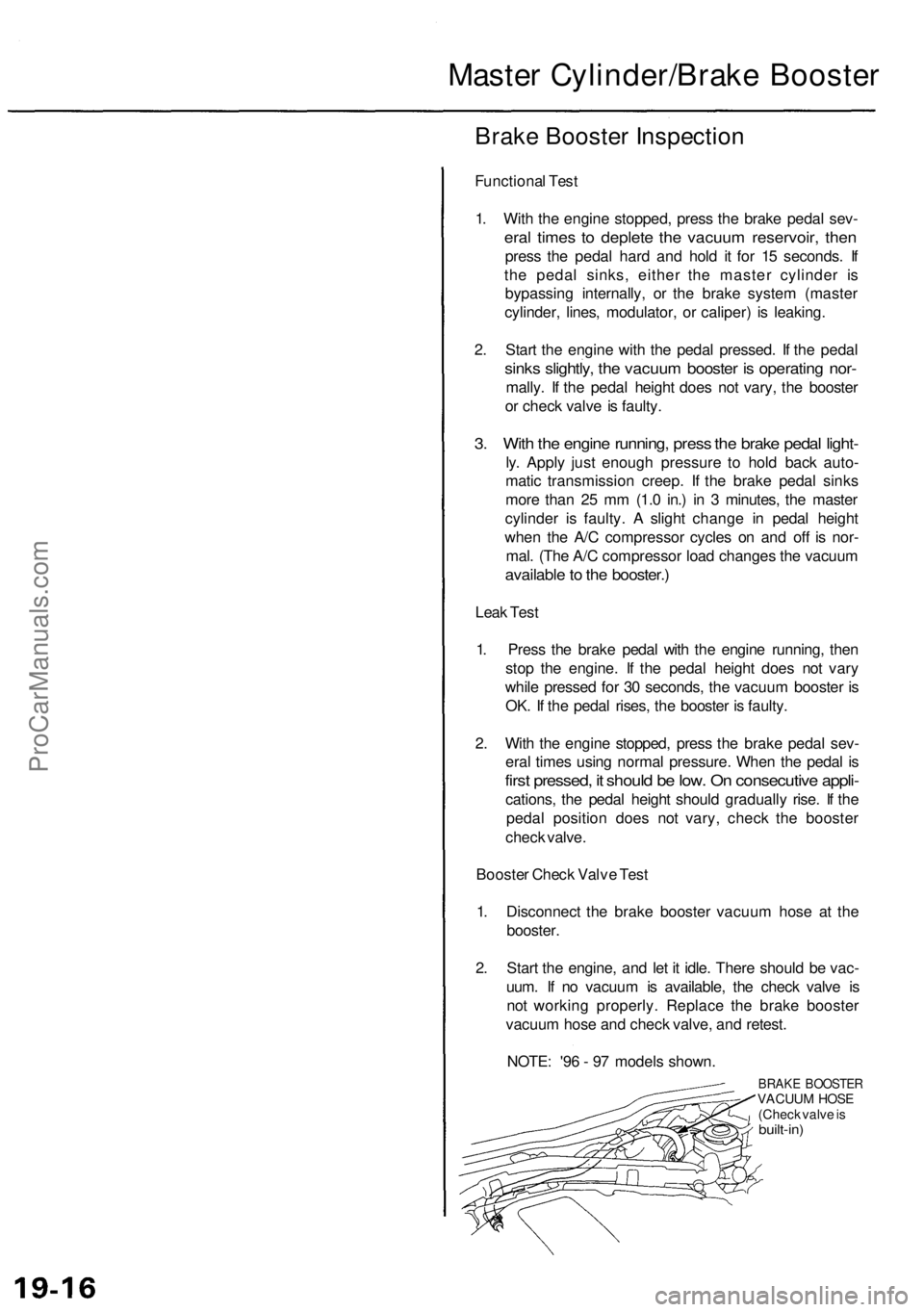
1 . Disconnec t th e brak e booste r vacuu m hos e a t th e
booster .
2 . Star t th e engine , an d le t i t idle . Ther e shoul d b e vac -
uum . I f n o vacuu m is available , th e chec k valv e i s
no t workin g properly . Replac e th e brak e booste r
vacuu m hos e an d chec k valve , an d retest .
NOTE : '9 6 - 9 7 model s shown .
BRAKE BOOSTE RVACUUM HOS E
(Chec k valv e is
built-in )
ProCarManuals.com