Page 1553 of 2543
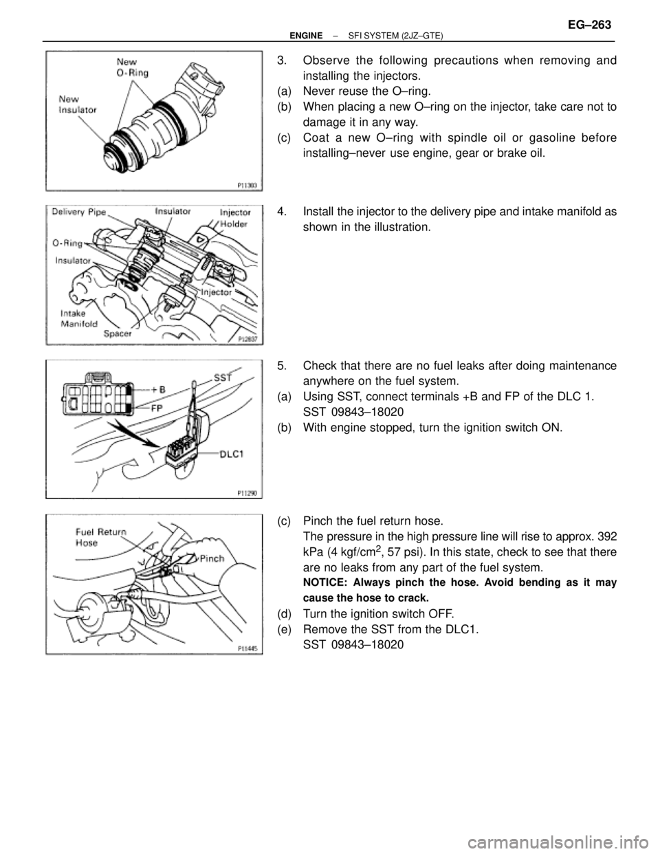
3. Observe the following precautions when removing and
installing the injectors.
(a) Never reuse the O±ring.
(b) When placing a new O±ring on the injector, take care not to
damage it in any way.
(c) Coat a new O±ring with spindle oil or gasoline before
installing±never use engine, gear or brake oil.
4. Install the injector to the delivery pipe and intake manifold as
shown in the illustration.
5. Check that there are no fuel leaks after doing maintenance
anywhere on the fuel system.
(a) Using SST, connect terminals +B and FP of the DLC 1.
SST 09843±18020
(b) With engine stopped, turn the ignition switch ON.
(c) Pinch the fuel return hose.
The pressure in the high pressure line will rise to approx. 392
kPa (4 kgf/cm
2, 57 psi). In this state, check to see that there
are no leaks from any part of the fuel system.
NOTICE: Always pinch the hose. Avoid bending as it may
cause the hose to crack.
(d) Turn the ignition switch OFF.
(e) Remove the SST from the DLC1.
SST 09843±18020
± ENGINESFI SYSTEM (2JZ±GTE)EG±263
Page 1554 of 2543
FUEL PUMP
ON±VEHICLE INSPECTION
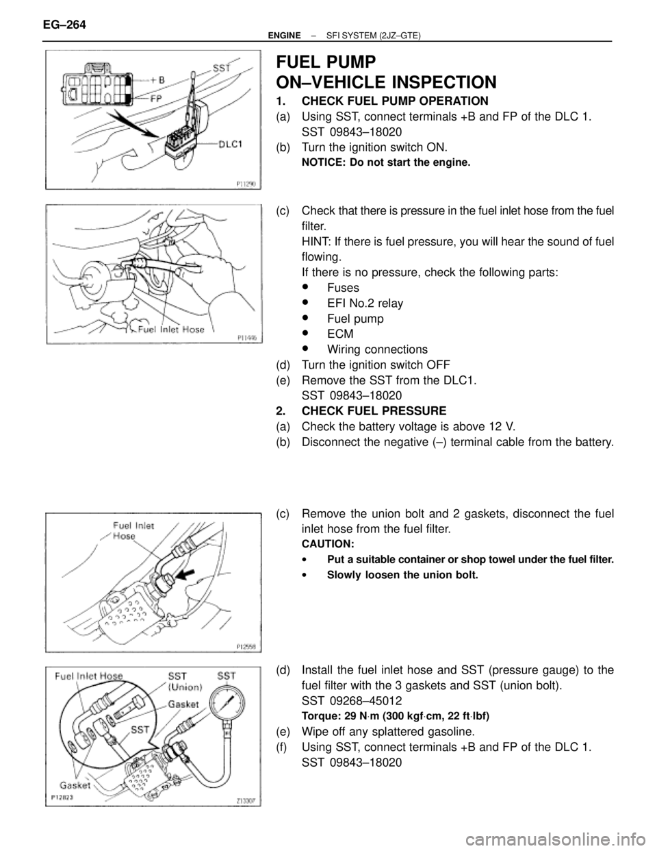
1. CHECK FUEL PUMP OPERATION
(a) Using SST, connect terminals +B and FP of the DLC 1.
SST 09843±18020
(b) Turn the ignition switch ON.
NOTICE: Do not start the engine.
(c) Check that there is pressure in the fuel inlet hose from the fuel
filter.
HINT: If there is fuel pressure, you will hear the sound of fuel
flowing.
If there is no pressure, check the following parts:
wFuses
wEFI No.2 relay
wFuel pump
wECM
wWiring connections
(d) Turn the ignition switch OFF
(e) Remove the SST from the DLC1.
SST 09843±18020
2. CHECK FUEL PRESSURE
(a) Check the battery voltage is above 12 V.
(b) Disconnect the negative (±) terminal cable from the battery.
(c) Remove the union bolt and 2 gaskets, disconnect the fuel
inlet hose from the fuel filter.
CAUTION:
wPut a suitable container or shop towel under the fuel filter.
wSlowly loosen the union bolt.
(d) Install the fuel inlet hose and SST (pressure gauge) to the
fuel filter with the 3 gaskets and SST (union bolt).
SST 09268±45012
Torque: 29 NVm (300 kgfVcm, 22 ftVlbf)
(e) Wipe off any splattered gasoline.
(f) Using SST, connect terminals +B and FP of the DLC 1.
SST 09843±18020 EG±264
± ENGINESFI SYSTEM (2JZ±GTE)
Page 1555 of 2543
(g) Reconnect the negative (±) terminal cable to the battery.
(h) Turn the ignition switch ON.
(i) Measure the fuel pressure.
Fuel pressure:
226±275 kPa (2.3±2.8 kgf/cm
2, 33±40 psi)
If pressure is high, replace the fuel pressure regulator.
If pressure is low, check the following parts:
wFuel hoses and connections
wFuel pump
wFuel filter
wFuel pressure regulator
(j) Remove the SST from the DLC1.
SST 09843±18020
(k) Start the engine.
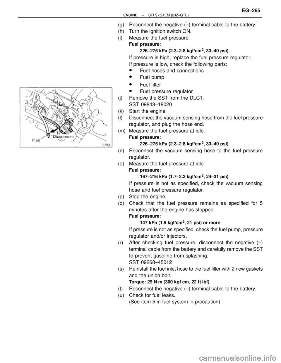
(l) Disconnect the vacuum sensing hose from the fuel pressure
regulator, and plug the hose end.
(m) Measure the fuel pressure at idle.
Fuel pressure:
226±275 kPa (2.3±2.8 kgf/cm
2, 33±40 psi)
(n) Reconnect the vacuum sensing hose to the fuel pressure
regulator.
(o) Measure the fuel pressure at idle.
Fuel pressure:
167±216 kPa (1.7±2.2 kgf/cm
2, 24±31 psi)
If pressure is not as specified, check the vacuum sensing
hose and fuel pressure regulator.
(p) Stop the engine.
(q) Check that the fuel pressure remains as specified for 5
minutes after the engine has stopped.
Fuel pressure:
147 kPa (1.5 kgf/cm
2, 21 psi) or more
If pressure is not as specified, check the fuel pump, pressure
regulator and/or injectors.
(r) After checking fuel pressure, disconnect the negative (±)
terminal cable from the battery and carefully remove the SST
to prevent gasoline from splashing.
SST 09268±45012
(s) Reinstall the fuel inlet hose to the fuel filter with 2 new gaskets
and the union bolt.
Torque: 29 NVm (300 kgfVcm, 22 ftVlbf)
(t) Reconnect the negative (±) terminal cable to the battery.
(u) Check for fuel leaks.
(See item 5 in fuel system in precaution)
± ENGINESFI SYSTEM (2JZ±GTE)EG±265
Page 1571 of 2543
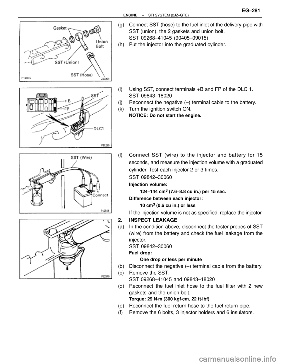
(g) Connect SST (hose) to the fuel inlet of the delivery pipe with
SST (union), the 2 gaskets and union bolt.
SST 09268±41045 (90405±09015)
(h) Put the injector into the graduated cylinder.
(i) Using SST, connect terminals +B and FP of the DLC 1.
SST 09843±18020
(j) Reconnect the negative (±) terminal cable to the battery.
(k) Turn the ignition switch ON.
NOTICE: Do not start the engine.
(l) Connect SST (wire) to the injector and battery for 15
seconds, and measure the injection volume with a graduated
cylinder. Test each injector 2 or 3 times.
SST 09842±30060
Injection volume:
124±144 cm
3 (7.6±8.8 cu in.) per 15 sec.
Difference between each injector:
10 cm
3 (0.6 cu in.) or less
If the injection volume is not as specified, replace the injector.
2. INSPECT LEAKAGE
(a) In the condition above, disconnect the tester probes of SST
(wire) from the battery and check the fuel leakage from the
injector.
SST 09842±30060
Fuel drop:
One drop or less per minute
(b) Disconnect the negative (±) terminal cable from the battery.
(c) Remove the SST.
SST 09268±41045 and 09843±18020
(d) Reconnect the fuel inlet hose to the fuel filter with 2 new
gaskets and the union bolt.
Torque: 29 NVm (300 kgfVcm, 22 ftVlbf)
(e) Reconnect the fuel return hose to the fuel return pipe.
(f) Remove the 6 bolts, 3 injector holders and 6 insulators.
± ENGINESFI SYSTEM (2JZ±GTE)EG±281
Page 1578 of 2543
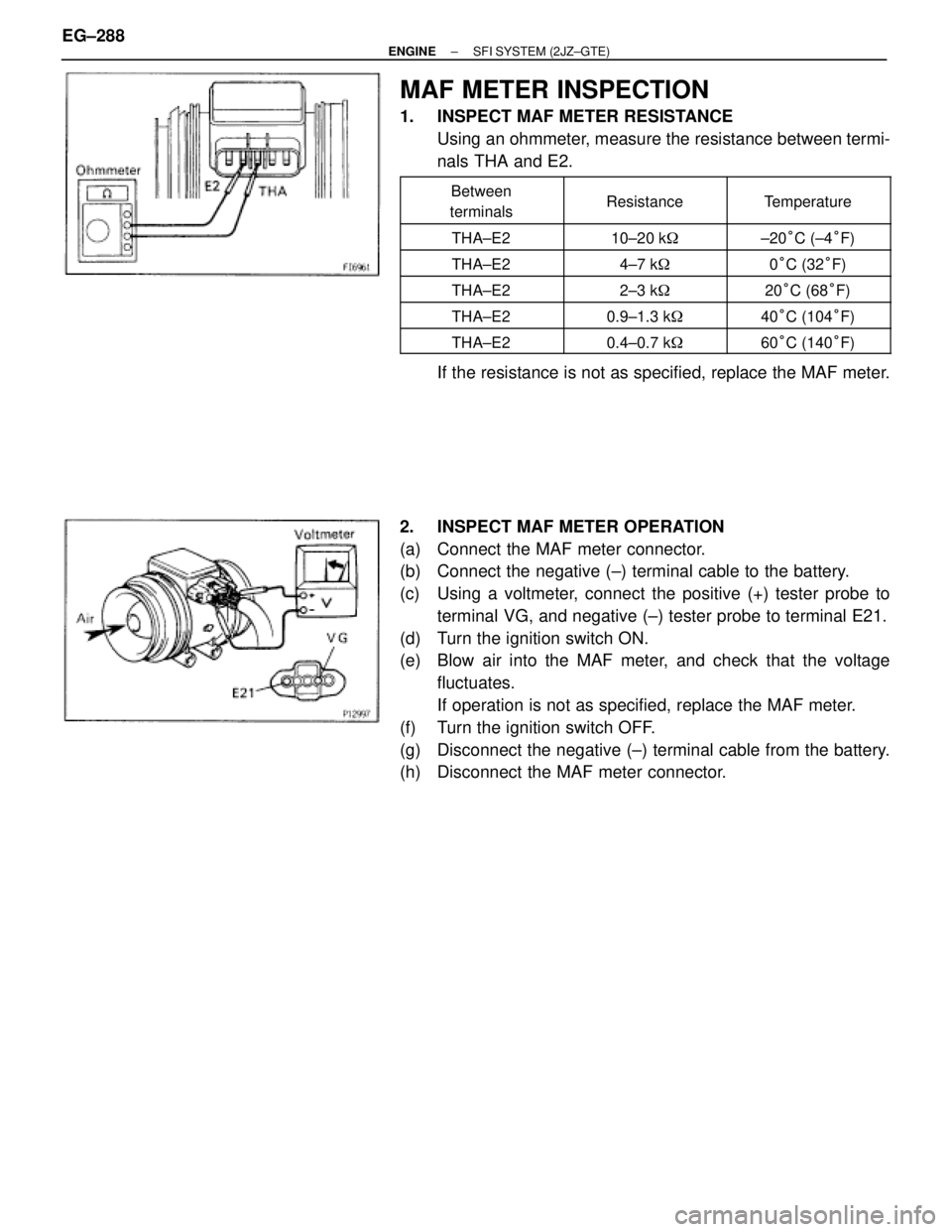
MAF METER INSPECTION
1. INSPECT MAF METER RESISTANCE
Using an ohmmeter, measure the resistance between termi-
nals THA and E2.
�������� �
������� ��������
Between
terminals�������� �
������� ��������Resistance
�������� �
������� ��������Temperature
�������� ��������THA±E2�������� ��������10±20 k��������� ��������±20°C (±4°F)
�������� ��������THA±E2�������� ��������4±7 k��������� ��������0°C (32°F)
�������� ��������THA±E2�������� ��������2±3 k��������� ��������20°C (68°F)�������� ��������THA±E2�������� ��������0.9±1.3 k��������� ��������40°C (104°F)�������� ��������THA±E2�������� ��������0.4±0.7 k��������� ��������60°C (140°F)
If the resistance is not as specified, replace the MAF meter.
2. INSPECT MAF METER OPERATION
(a) Connect the MAF meter connector.
(b) Connect the negative (±) terminal cable to the battery.
(c) Using a voltmeter, connect the positive (+) tester probe to
terminal VG, and negative (±) tester probe to terminal E21.
(d) Turn the ignition switch ON.
(e) Blow air into the MAF meter, and check that the voltage
fluctuates.
If operation is not as specified, replace the MAF meter.
(f) Turn the ignition switch OFF.
(g) Disconnect the negative (±) terminal cable from the battery.
(h) Disconnect the MAF meter connector. EG±288
± ENGINESFI SYSTEM (2JZ±GTE)
Page 1604 of 2543
TURBO PRESSURE SENSOR
COMPONENTS FOR REMOVAL AND
INSTALLATION
TURBO PRESSURE SENSOR
INSPECTION
1. INSPECT POWER SOURCE VOLTAGE OF TURBO
PRESSURE SENSOR
(a) Disconnect the turbo pressure sensor connector.
(b) Turn the ignition switch ON.
(c) Using a voltmeter, measure the voltage between connector
terminals VC and E2 of the wiring harness side.
Voltage:
4.5±5.5 V
(d) Turn the ignition switch OFF.
(e) Reconnect the turbo pressure sensor connector. EG±314
± ENGINESFI SYSTEM (2JZ±GTE)
Page 1605 of 2543
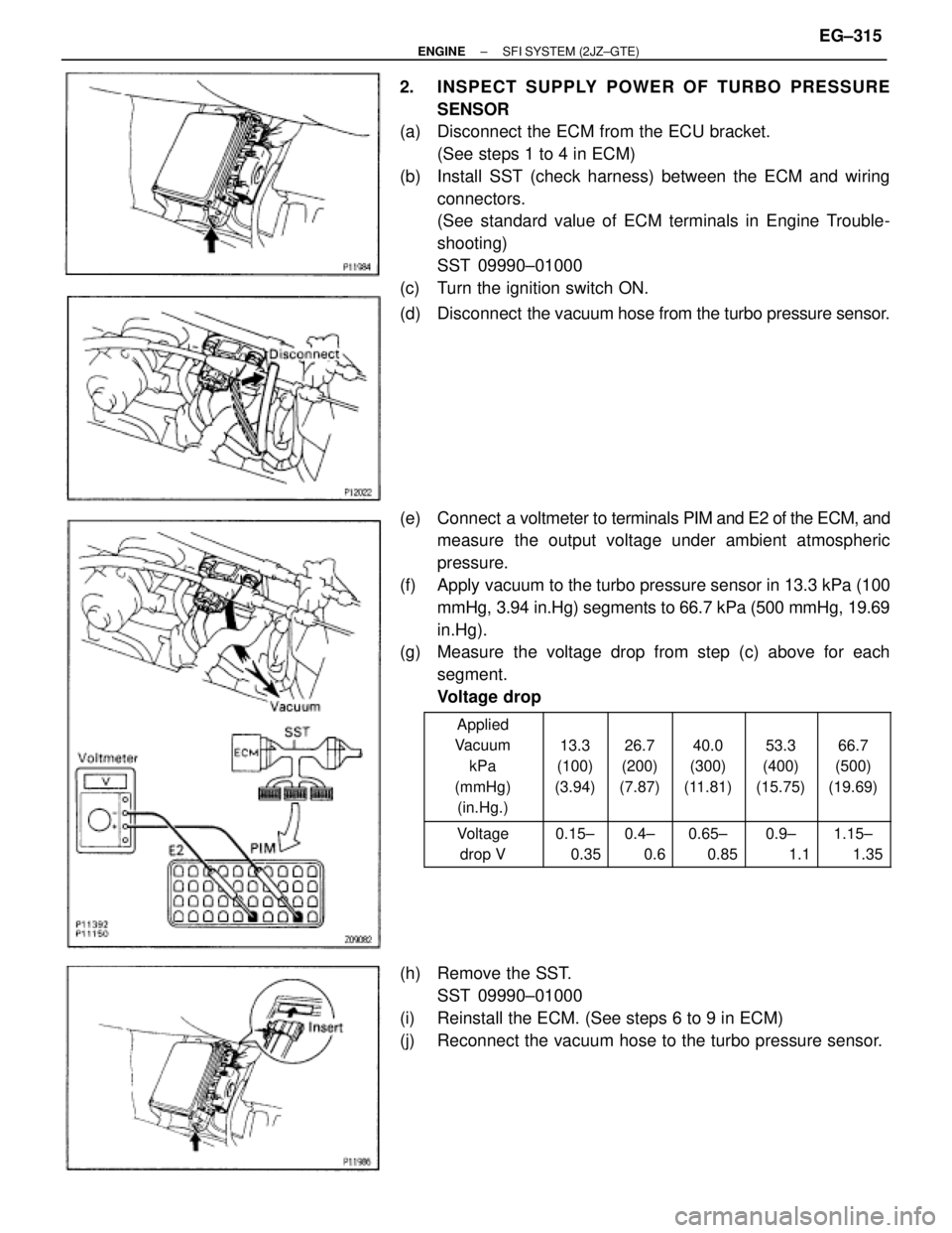
2. INSPECT SUPPLY POWER OF TURBO PRESSURE
SENSOR
(a) Disconnect the ECM from the ECU bracket.
(See steps 1 to 4 in ECM)
(b) Install SST (check harness) between the ECM and wiring
connectors.
(See standard value of ECM terminals in Engine Trouble-
shooting)
SST 09990±01000
(c) Turn the ignition switch ON.
(d) Disconnect the vacuum hose from the turbo pressure sensor.
(e) Connect a voltmeter to terminals PIM and E2 of the ECM, and
measure the output voltage under ambient atmospheric
pressure.
(f) Apply vacuum to the turbo pressure sensor in 13.3 kPa (100
mmHg, 3.94 in.Hg) segments to 66.7 kPa (500 mmHg, 19.69
in.Hg).
(g) Measure the voltage drop from step (c) above for each
segment.
Voltage drop
������ �
����� �
����� �
����� �
����� ������
Applied
Vacuum
kPa
(mmHg)
(in.Hg.)���� �
��� �
��� �
��� �
��� ����
13.3
(100)
(3.94)
���� �
��� �
��� �
��� �
��� ����
26.7
(200)
(7.87)
���� �
��� �
��� �
��� �
��� ����
40.0
(300)
(11.81)
���� �
��� �
��� �
��� �
��� ����
53.3
(400)
(15.75)
���� �
��� �
��� �
��� �
��� ����
66.7
(500)
(19.69)
������ �
����� ������
Voltage
drop V���� �
��� ����
0.15±
0.35���� �
��� ����
0.4±
0.6���� �
��� ����
0.65±
0.85���� �
��� ����
0.9±
1.1���� �
��� ����
1.15±
1.35
(h) Remove the SST.
SST 09990±01000
(i) Reinstall the ECM. (See steps 6 to 9 in ECM)
(j) Reconnect the vacuum hose to the turbo pressure sensor.
± ENGINESFI SYSTEM (2JZ±GTE)EG±315
Page 1616 of 2543
FUEL CUT RPM
FUEL CUT RPM INSPECTION
1. WARM UP ENGINE
Allow the engine to warm up to normal operating tempera-
ture.
2. CONNECT TACHOMETER TO ENGINE
Connect the tester probe of a tachometer to terminal IG� of
the DLC1.
NOTICE:
wNever allow the tachometer terminal to touch ground as
it could result in damage to the igniter and/or ignition
coil.
wAs some tachometers are not compatible with this igni-
tion system, we recommend that you confirm the compat-
ibility of your unit before use.
3. INSPECT FUEL CUTOFF OPERATION
(a) Increase the engine speed to at least 3,000 rpm.
(b) Check for injector operating noise.
(c) Check that when the throttle lever is released, injector
operation noise stops momentarily and then resumes.
HINT: Measure with the A/C OFF.
Fuel return speed:
1,400 rpm
(Vehicle speed less than 25 km/h (16mph), with
brake OFF)
4. DISCONNECT TACHOMETER EG±326
± ENGINESFI SYSTEM (2JZ±GTE)