Page 1332 of 2543
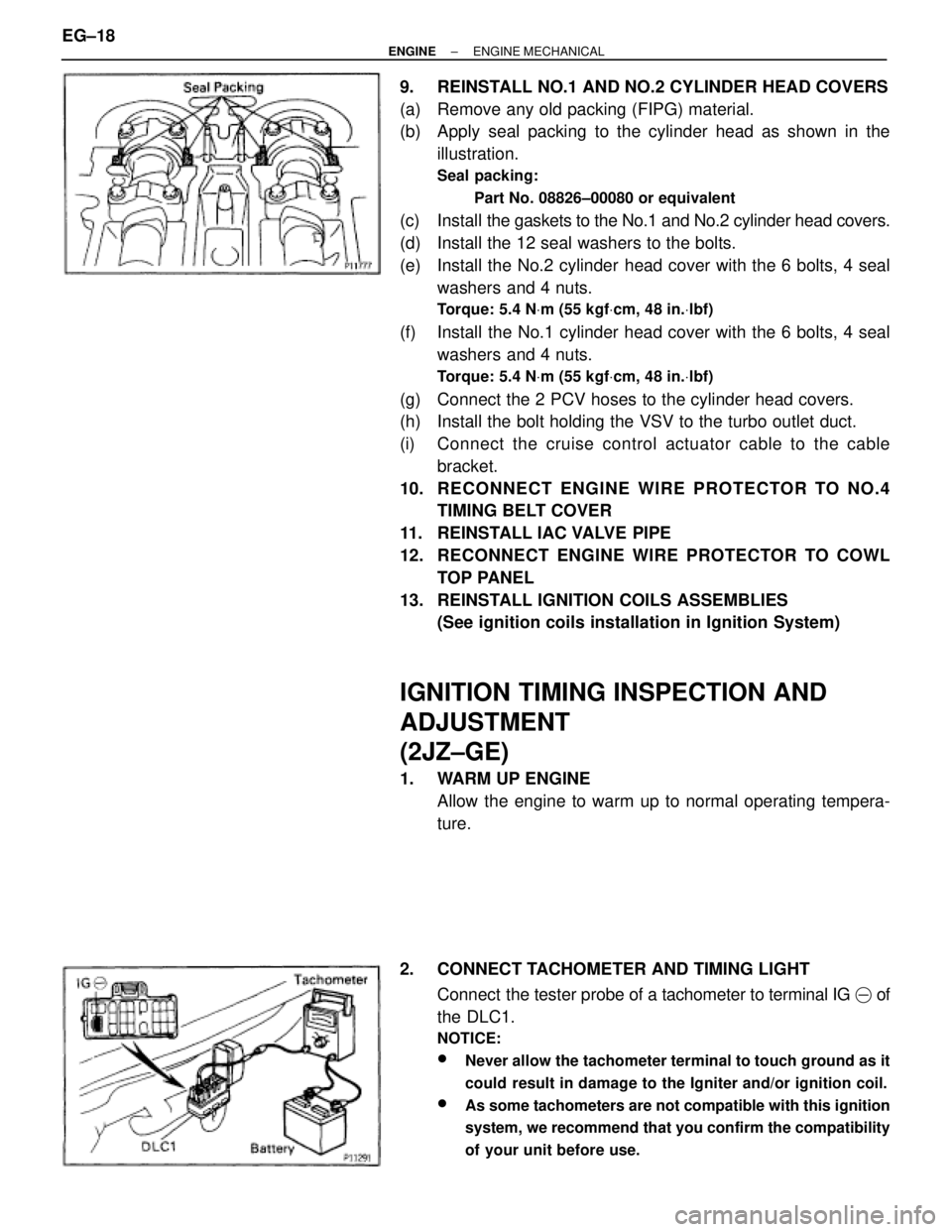
9. REINSTALL NO.1 AND NO.2 CYLINDER HEAD COVERS
(a) Remove any old packing (FIPG) material.
(b) Apply seal packing to the cylinder head as shown in the
illustration.
Seal packing:
Part No. 08826±00080 or equivalent
(c) Install the gaskets to the No.1 and No.2 cylinder head covers.
(d) Install the 12 seal washers to the bolts.
(e) Install the No.2 cylinder head cover with the 6 bolts, 4 seal
washers and 4 nuts.
Torque: 5.4 NVm (55 kgfVcm, 48 in.Vlbf)
(f) Install the No.1 cylinder head cover with the 6 bolts, 4 seal
washers and 4 nuts.
Torque: 5.4 NVm (55 kgfVcm, 48 in.Vlbf)
(g) Connect the 2 PCV hoses to the cylinder head covers.
(h) Install the bolt holding the VSV to the turbo outlet duct.
(i) Connect the cruise control actuator cable to the cable
bracket.
10. RECONNECT ENGINE WIRE PROTECTOR TO NO.4
TIMING BELT COVER
11. REINSTALL IAC VALVE PIPE
12. RECONNECT ENGINE WIRE PROTECTOR TO COWL
TOP PANEL
13. REINSTALL IGNITION COILS ASSEMBLIES
(See ignition coils installation in Ignition System)
IGNITION TIMING INSPECTION AND
ADJUSTMENT
(2JZ±GE)
1. WARM UP ENGINE
Allow the engine to warm up to normal operating tempera-
ture.
2. CONNECT TACHOMETER AND TIMING LIGHT
Connect the tester probe of a tachometer to terminal IG � of
the DLC1.
NOTICE:
wNever allow the tachometer terminal to touch ground as it
could result in damage to the Igniter and/or ignition coil.
wAs some tachometers are not compatible with this ignition
system, we recommend that you confirm the compatibility
of your unit before use.
EG±18± ENGINEENGINE MECHANICAL
Page 1333 of 2543
3. CHECK IDLE SPEED
(a) Race the engine speed at 2,500 rpm for approx. 90 seconds.
(b) Check the idle speed.
Idle speed:
700 + 50 rpm
4. ADJUST IGNITION TIMING
(a) Using SST, connect terminals TE1 and E1 of the DLC 1.
SST 09843±18020
(b) Using a timing light, check the ignition timing.
Ignition timing:
10 + 2° BTDC @ idle
(Transmission in neutral position)
(c) Loosen the nut, and adjust by turning the distributor.
Ignition timing:
10° BTDC @ idle
(Transmission in neutral position)
(d) Tighten the nut, and recheck the ignition timing.
Torque: 19 NVm (195 kgfVcm, 14 ftVlbf)
(e) Remove the SST from the DLC1.
SST 09843±18020
5. FURTHER CHECK IGNITION TIMING
Ignition timing:
7±19° BTDC @ idle
(Transmission in neutral position)
HINT: The timing mark moves in a range between 75 and 195.
6. DISCONNECT TACHOMETER AND TIMING LIGHT
± ENGINEENGINE MECHANICALEG±19
Page 1334 of 2543
IGNITION TIMING INSPECTION
(2JZ±GTE)
1. WARM UP ENGINE
Allow the engine to warm up to normal operating tempera-
ture.
2. CONNECT TACHOMETER AND TIMING LIGHT
(See step 2 in ignition timing inspection and adjustment
(2JZ±GE))
3. CHECK IDLE SPEED
(a) Race the engine speed at 2,500 rpm for approx. 90 seconds.
(b) Check the idle speed.
Idle speed:
650 + 50 rpm
4. CHECK IGNITION TIMING
(a) Using SST, connect terminals TE1 and E1 of the DLC 1.
SST 09843±18020
(b) Open the igniter connector cover and remove the green lead
wire.
(c) Connect the timing light clip to the green lead wire.
NOTICE:
wUse a timing light that can detect the primary signal.
wAfter finishing the inspection, make sure the lead wire is
stored inside the connector cover.
EG±20± ENGINEENGINE MECHANICAL
Page 1335 of 2543
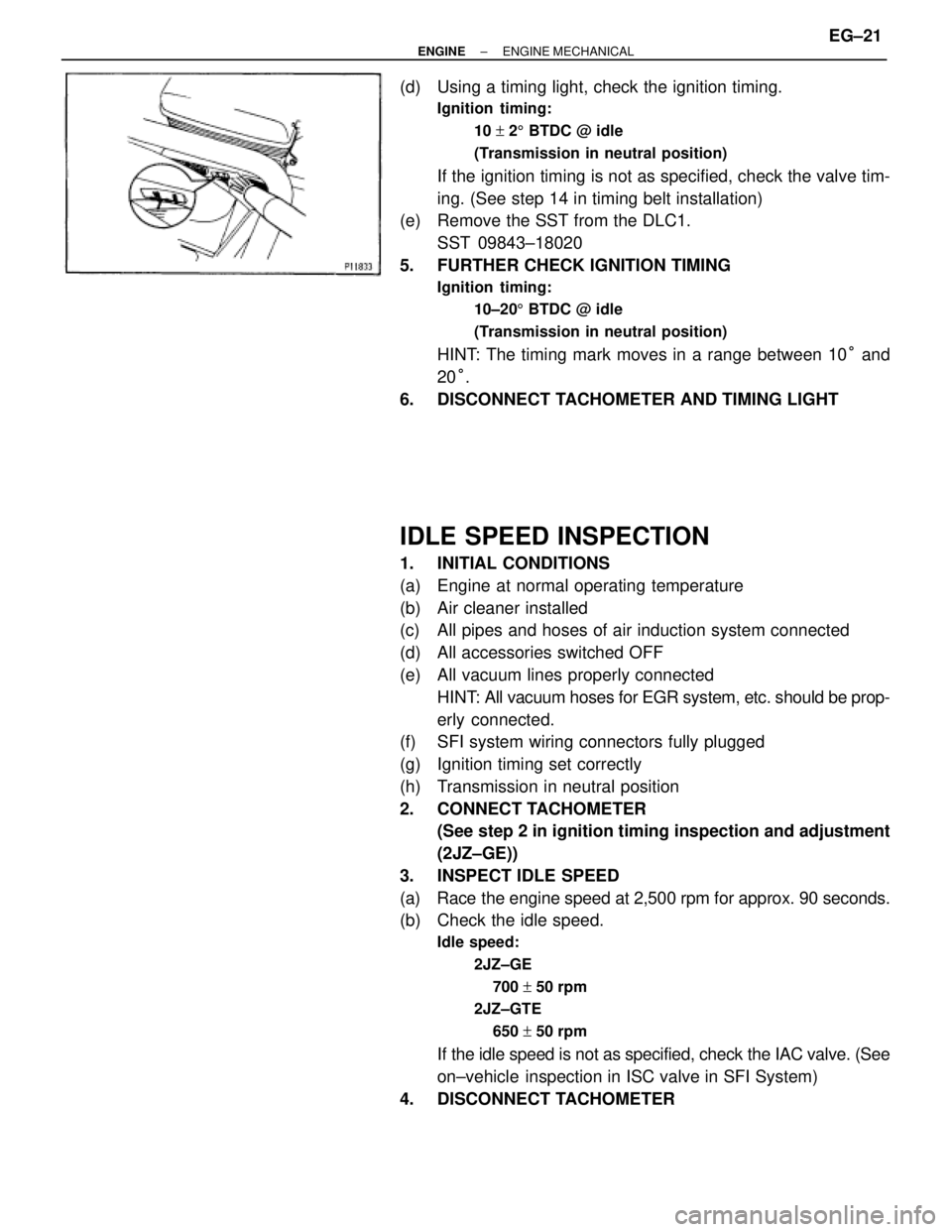
(d) Using a timing light, check the ignition timing.
Ignition timing:
10 + 25 BTDC @ idle
(Transmission in neutral position)
If the ignition timing is not as specified, check the valve tim-
ing. (See step 14 in timing belt installation)
(e) Remove the SST from the DLC1.
SST 09843±18020
5. FURTHER CHECK IGNITION TIMING
Ignition timing:
10±205 BTDC @ idle
(Transmission in neutral position)
HINT: The timing mark moves in a range between 10° and
20°.
6. DISCONNECT TACHOMETER AND TIMING LIGHT
IDLE SPEED INSPECTION
1. INITIAL CONDITIONS
(a) Engine at normal operating temperature
(b) Air cleaner installed
(c) All pipes and hoses of air induction system connected
(d) All accessories switched OFF
(e) All vacuum lines properly connected
HINT: All vacuum hoses for EGR system, etc. should be prop-
erly connected.
(f) SFI system wiring connectors fully plugged
(g) Ignition timing set correctly
(h) Transmission in neutral position
2. CONNECT TACHOMETER
(See step 2 in ignition timing inspection and adjustment
(2JZ±GE))
3. INSPECT IDLE SPEED
(a) Race the engine speed at 2,500 rpm for approx. 90 seconds.
(b) Check the idle speed.
Idle speed:
2JZ±GE
700 + 50 rpm
2JZ±GTE
650 + 50 rpm
If the idle speed is not as specified, check the IAC valve. (See
on±vehicle inspection in ISC valve in SFI System)
4. DISCONNECT TACHOMETER
± ENGINEENGINE MECHANICALEG±21
Page 1356 of 2543
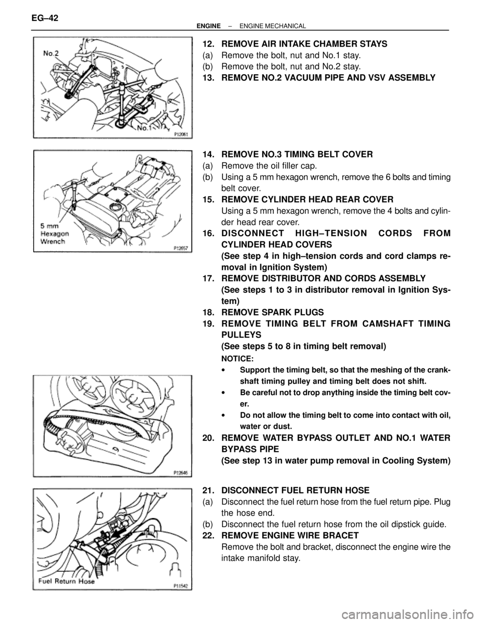
12. REMOVE AIR INTAKE CHAMBER STAYS
(a) Remove the bolt, nut and No.1 stay.
(b) Remove the bolt, nut and No.2 stay.
13. REMOVE NO.2 VACUUM PIPE AND VSV ASSEMBLY
14. REMOVE NO.3 TIMING BELT COVER
(a) Remove the oil filler cap.
(b) Using a 5 mm hexagon wrench, remove the 6 bolts and timing
belt cover.
15. REMOVE CYLINDER HEAD REAR COVER
Using a 5 mm hexagon wrench, remove the 4 bolts and cylin-
der head rear cover.
16. D I S C O N N E C T H I G H ± T E N S I O N C O R D S F R O M
CYLINDER HEAD COVERS
(See step 4 in high±tension cords and cord clamps re-
moval in Ignition System)
17. REMOVE DISTRIBUTOR AND CORDS ASSEMBLY
(See steps 1 to 3 in distributor removal in Ignition Sys-
tem)
18. REMOVE SPARK PLUGS
19. RE MO V E TIMING BE LT FRO M CAMS HAFT TIMING
PULLEYS
(See steps 5 to 8 in timing belt removal)
NOTICE:
wSupport the timing belt, so that the meshing of the crank-
shaft timing pulley and timing belt does not shift.
wBe careful not to drop anything inside the timing belt cov-
er.
wDo not allow the timing belt to come into contact with oil,
water or dust.
20. REMOVE WATER BYPASS OUTLET AND NO.1 WATER
BYPASS PIPE
(See step 13 in water pump removal in Cooling System)
21. DISCONNECT FUEL RETURN HOSE
(a) Disconnect the fuel return hose from the fuel return pipe. Plug
the hose end.
(b) Disconnect the fuel return hose from the oil dipstick guide.
22. REMOVE ENGINE WIRE BRACET
Remove the bolt and bracket, disconnect the engine wire the
intake manifold stay. EG±42
± ENGINEENGINE MECHANICAL
Page 1363 of 2543
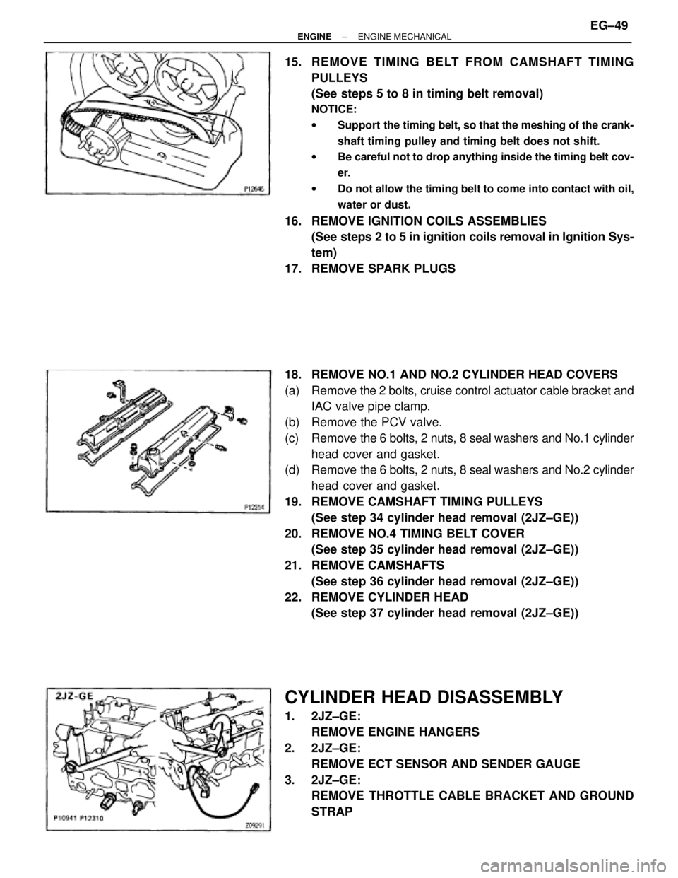
15. REMOVE TIMING BELT FROM CAMSHAFT TIMING
PULLEYS
(See steps 5 to 8 in timing belt removal)
NOTICE:
wSupport the timing belt, so that the meshing of the crank-
shaft timing pulley and timing belt does not shift.
wBe careful not to drop anything inside the timing belt cov-
er.
wDo not allow the timing belt to come into contact with oil,
water or dust.
16. REMOVE IGNITION COILS ASSEMBLIES
(See steps 2 to 5 in ignition coils removal in Ignition Sys-
tem)
17. REMOVE SPARK PLUGS
18. REMOVE NO.1 AND NO.2 CYLINDER HEAD COVERS
(a) Remove the 2 bolts, cruise control actuator cable bracket and
IAC valve pipe clamp.
(b) Remove the PCV valve.
(c) Remove the 6 bolts, 2 nuts, 8 seal washers and No.1 cylinder
head cover and gasket.
(d) Remove the 6 bolts, 2 nuts, 8 seal washers and No.2 cylinder
head cover and gasket.
19. REMOVE CAMSHAFT TIMING PULLEYS
(See step 34 cylinder head removal (2JZ±GE))
20. REMOVE NO.4 TIMING BELT COVER
(See step 35 cylinder head removal (2JZ±GE))
21. REMOVE CAMSHAFTS
(See step 36 cylinder head removal (2JZ±GE))
22. REMOVE CYLINDER HEAD
(See step 37 cylinder head removal (2JZ±GE))
CYLINDER HEAD DISASSEMBLY
1. 2JZ±GE:
REMOVE ENGINE HANGERS
2. 2JZ±GE:
REMOVE ECT SENSOR AND SENDER GAUGE
3. 2JZ±GE:
REMOVE THROTTLE CABLE BRACKET AND GROUND
STRAP
± ENGINEENGINE MECHANICALEG±49
Page 1382 of 2543
19. INSTALL WATER BYPASS OUTLET AND NO.1 WATER
BYPASS PIPE
(See step 3 in water pump installation in Cooling System)
20. INSTALL TIMING BELT
(See steps 11 to 17 in timing belt removal)
21. INSTALL SPARK PLUGS
22. INSTALL DISTRIBUTOR AND CORDS ASSEMBLY
(See steps 2, 3 and 5 in distributor installation in Ignition
System)
23. CONNECT HIGH±TENSION CORDS TO CYLINDER HEAD
COVERS
(See step 1 in high±tension cords and cord clamps
installation in Ignition System)
24. INSTALL NO.3 TIMING BELT COVER
25. INSTALL CYLINDER HEAD REAR COVER
26. INSTALL NO.2 VACUUM PIPE AND VSV ASSEMBLY
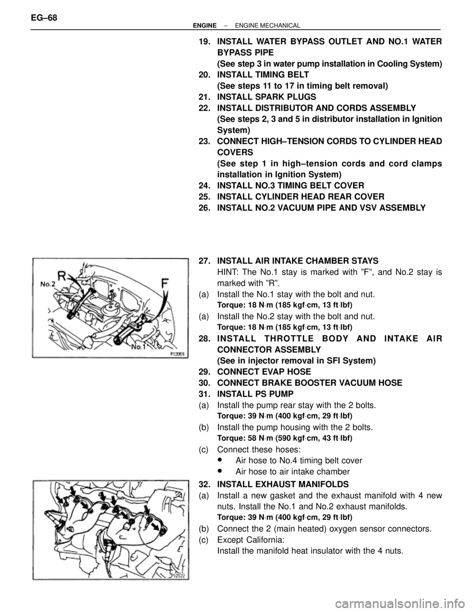
27. INSTALL AIR INTAKE CHAMBER STAYS
HINT: The No.1 stay is marked with ºFº, and No.2 stay is
marked with ºRº.
(a) Install the No.1 stay with the bolt and nut.
Torque: 18 NVm (185 kgfVcm, 13 ftVlbf)
(a) Install the No.2 stay with the bolt and nut.
Torque: 18 NVm (185 kgfVcm, 13 ftVlbf)
28. I N S TA L L T H R OTTLE BODY AND INTAKE AIR
CONNECTOR ASSEMBLY
(See in injector removal in SFI System)
29. CONNECT EVAP HOSE
30. CONNECT BRAKE BOOSTER VACUUM HOSE
31. INSTALL PS PUMP
(a) Install the pump rear stay with the 2 bolts.
Torque: 39 NVm (400 kgfVcm, 29 ftVlbf)
(b) Install the pump housing with the 2 bolts.
Torque: 58 NVm (590 kgfVcm, 43 ftVlbf)
(c) Connect these hoses:
wAir hose to No.4 timing belt cover
wAir hose to air intake chamber
32. INSTALL EXHAUST MANIFOLDS
(a) Install a new gasket and the exhaust manifold with 4 new
nuts. Install the No.1 and No.2 exhaust manifolds.
Torque: 39 NVm (400 kgfVcm, 29 ftVlbf)
(b) Connect the 2 (main heated) oxygen sensor connectors.
(c) Except California:
Install the manifold heat insulator with the 4 nuts. EG±68
± ENGINEENGINE MECHANICAL
Page 1383 of 2543
33. INSTALL NO.2 FRONT EXHAUST PIPE
(See step 6 in engine installation in Engine Mechanical)
34. INSTALL DRIVE BELT
35. INSTALL AIR CLEANER, VAF METER AND INTAKE AIR
CONNECTOR PIPE ASSEMBLY
(See step 22 in engine installation in Engine Mechanical)
36. INSTALL AIR CLEANER DUCT
37. FILL WITH ENGINE COOLANT
38. START ENGINE AND CHECK FOR LEAKS
39. CHECK IGNITION TIMING
(See steps 8 to 12 in distributor installation in Ignition
System)
40. INSTALL ENGINE UNDER COVER
41. PERFORM ROAD TEST
Check for abnormal noise, shock, slippage, correct shift
points and smooth operation.
42. RECHECK ENGINE COOLANT LEVEL
CYLINDER HEAD INSTALLATION
(2JZ±GTE)
1. INSTALL CYLINDER HEAD
(See step 1 in cylinder head installation (2JZ±GE))
2. INSTALL CAMSHAFTS
(See step 2 ((a) to (m)) in cylinder head installation (2JZ±
GE))
3. CHECK AND ADJUST VALVE CLEARANCE
(See steps 5 to 6 in valve clearance inspection and ad-
justment)
Turn the camshaft, and position the cam lobe upward, check
and adjust the valve clearance.
4. INSTALL NO.4 TIMING BELT COVER
(See step 4 in cylinder head installation (2JZ±GE))
5. INSTALL CAMSHAFT TIMING PULLEYS
(See step 5 in cylinder head installation (2JZ±GE))
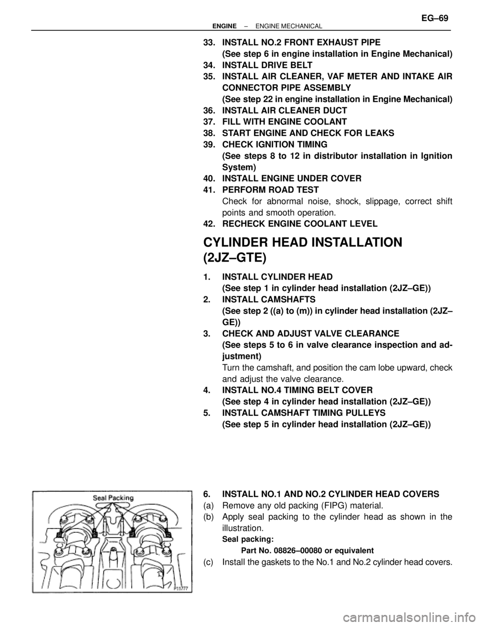
6. INSTALL NO.1 AND NO.2 CYLINDER HEAD COVERS
(a) Remove any old packing (FIPG) material.
(b) Apply seal packing to the cylinder head as shown in the
illustration.
Seal packing:
Part No. 08826±00080 or equivalent
(c) Install the gaskets to the No.1 and No.2 cylinder head covers.
± ENGINEENGINE MECHANICALEG±69