Page 1149 of 2543
DISTRIBUTOR
COMPONENTS FOR REMOVAL AND
INSTALLATION
DISTRIBUTOR REMOVAL
1. DISCONNECT DISTRIBUTOR CONNECTOR
2. DISCONNECT HIGH±TENSION CORDS FROM
DISTRIBUTOR
Disconnect the 7 high±tension cords from the distributor.
NOTICE: Pulling on or bending the cords may damage the con-
ductor inside.
3. REMOVE DISTRIBUTOR
(a) Remove the nut.
(b) Pull out the distributor.
(c) Remove the O±ring from the distributor housing. IG±14
± IGNITION SYSTEM2JZ±GE
Page 1150 of 2543
COMPONENTS FOR DISASSEMBLY AND
ASSEMBLY
DISTRIBUTOR DISASSEMBLY
Assembly is in the reverse order of disassembly.
1. REMOVE HEAT INSULATOR
Remove the 3 screws and heat insulator.
2. REMOVE DISTRIBUTOR CAP
Loosen the 3 bolts, and remove the distributor cap and O±
ring.
ASSEMBLY HINT: Use a new O±ring.
± IGNITION SYSTEM(2JZ±GE)IG±15
Page 1151 of 2543
3. REMOVE ROTOR
Remove the 2 screws and rotor.
ASSEMBLY HINT: Align the hollow of the signal rotor with the
protrusion of the rotor.
DISTRIBUTOR INSPECTION
INSPECT SHAFT
Turn the shaft and check that it is not rough or worn.
If it feels rough or worn, replace the distributor housing as-
sembly.
DISTRIBUTOR INSTALLATION
1. REMOVE NO.3 TIMING BELT COVER
(a) Remove the oil filler cap.
(b) Using a 5 mm hexagon wrench, remove the 6 bolts and timing
belt cover.
2. SET NO.1 CYLINDER TO TDC/COMPRESSION
(a) Turn the crankshaft pulley, and align its groove with timing
mark ºOº of the No.1 timing belt cover. IG±16
± IGNITION SYSTEM(2JZ±GE)
Page 1152 of 2543
(b) Check that the timing marks of the camshaft timing pulleys
and No.4 timing belt cover are aligned.
If not, turn the crankshaft 1 revolution (360°) and align the
mark as above.
3. INSTALL DISTRIBUTOR
(a) Install a new O±ring to the distributor housing.
(b) Apply a light coat of engine oil on the O±ring.
(c) Align the marks of the drive gear and distributor housing.
(d) Insert the distributor, aligning the protrusion of the flange with
that of the stud bolt on the cylinder head.
(e) Install the distributor with the nut. Lightly tighten the nut.
4. REINSTALL NO.3 TIMING BELT COVER
5. CONNECT HIGH±TENSION CORDS TO DISTRIBUTOR
Connect the 7 high±tension cords to the distributor.
Firing order:
1 ± 5 ± 3 ± 6 ± 2 ± 4
6. CONNECT DISTRIBUTOR CONNECTOR
7. ADJST IGNITION TIMING
(See ignition timing inspection and adjustment)
± IGNITION SYSTEM(2JZ±GE)IG±17
Page 1153 of 2543

SERVICE SPECIFICATIONS
SERVICE DATA
������� �������Firing order��������������� ���������������±���������������� ����������������1 ± 5 ± 3 ± 6 ± 2 ± 4������� �
������ �������High±tension
cord��������������� �
�������������� ���������������Resistance Limit���������������� �
��������������� ����������������25 k� per cord
������� �
������ �
������ �
������ �������
Spark plug��������������� �
�������������� �
�������������� �
�������������� ���������������
Recommended spark plug ND
NGK
Correct electrode gap for new plug
Maximum electrode gap for used plug���������������� �
��������������� �
��������������� �
��������������� ����������������
PK16R11
BKR5EP11
1.1 mm (0.043 in.)
1.3 mm (0.051 in.)
������� �
������ �
������ �
������ �������
Ignition coil��������������� �
�������������� �
�������������� �
�������������� ���������������
Primary coil resistance at cold
at hot
Secondary coil resistance at cold
at hot���������������� �
��������������� �
��������������� �
��������������� ����������������
0.36±0.55 �
0.45±0.65 �
9.0±15.4 k�
11.4±18.1 k�
������� �
������ �
������ �
������ �
������ �
������ �������
Distributor��������������� �
�������������� �
�������������� �
�������������� �
�������������� �
�������������� ���������������
Air gap
Pickup coil resistance at cold G1±G�
G2±G�
NE±G�
at hot G1±G�
G2±G�
NE±G����������������� �
��������������� �
��������������� �
��������������� �
��������������� �
��������������� ����������������
0.2±0.5 mm (0.008±0.020 in.)
125±200 �
125±200 �
155±250 �
160±235 �
160±235 �
190±290 �
TORQUE SPECIFICATIONS
����������������� �����������������Part tightened������� �������NVm������� �������kgfVcm������� �������ftVlbf
����������������� �����������������Spark plug x Cylinder head������� �������18������� �������180������� �������13
IG±18± IGNITION SYSTEM2JZ±GE
Page 1154 of 2543
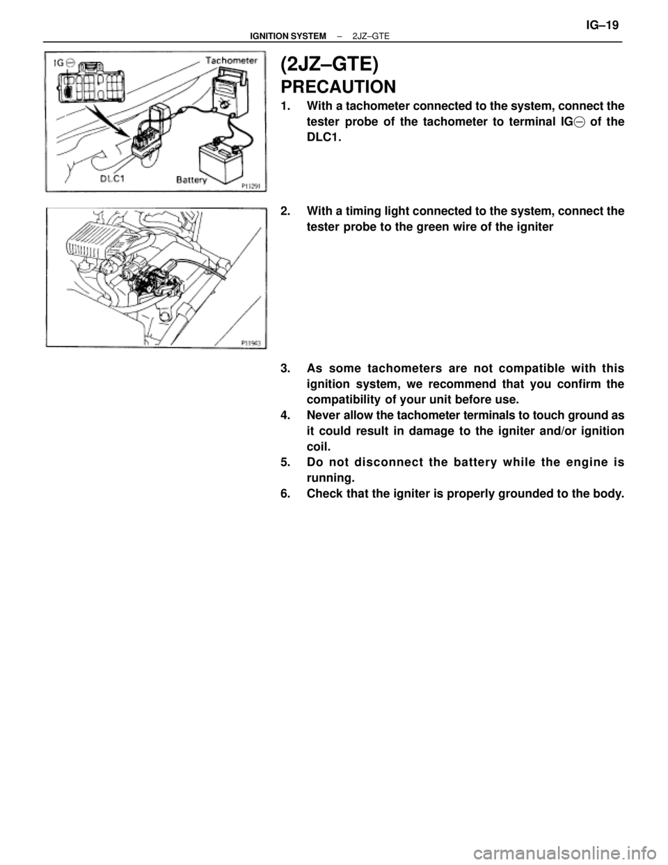
(2JZ±GTE)
PRECAUTION
1. With a tachometer connected to the system, connect the
tester probe of the tachometer to terminal IG� of the
DLC1.
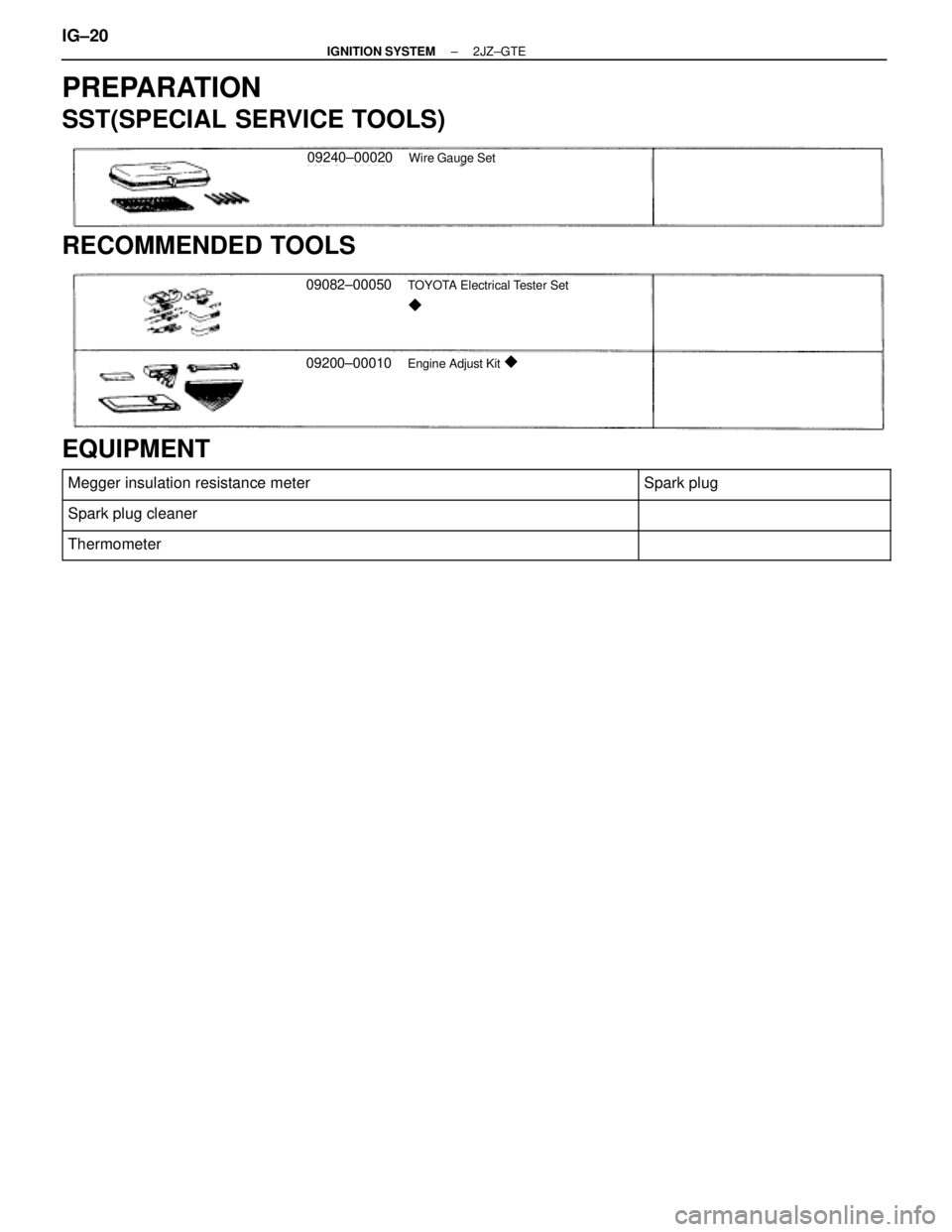
2. With a timing light connected to the system, connect the
tester probe to the green wire of the igniter
3. As some tachometers are not compatible with this
ignition system, we recommend that you confirm the
compatibility of your unit before use.
4. Never allow the tachometer terminals to touch ground as
it could result in damage to the igniter and/or ignition
coil.
5. Do not disconnect the battery while the engine is
running.
6. Check that the igniter is properly grounded to the body.
± IGNITION SYSTEM2JZ±GTEIG±19
Page 1155 of 2543
PREPARATION
SST(SPECIAL SERVICE TOOLS)
09240±00020Wire Gauge Set
RECOMMENDED TOOLS
09082±00050TOYOTA Electrical Tester Set
�
09200±00010Engine Adjust Kit �
EQUIPMENT
������������������������� �������������������������Megger insulation resistance meter������������ ������������Spark plug������������������������� �
������������������������ �������������������������Spark plug cleaner
������������ �
����������� ������������
������������������������� �������������������������Thermometer������������ ������������
IG±20± IGNITION SYSTEM2JZ±GTE
Page 1156 of 2543
 Remove the ignition coil. (See ignition coil removal)
(b) Remove the spark plug.
(c) Install the spark plug to the ignition coil, and c")
ON±VEHICLE INSPECTION
SPARK TEST
CHECK THAT SPARK OCCURS
(a) Remove the ignition coil. (See ignition coil removal)
(b) Remove the spark plug.
(c) Install the spark plug to the ignition coil, and connect the
ignition coil connecter.
(d) Ground the spark plug.
(e) Check if spark occurs while engine is being cranked.
HINT: To prevent gasoline from being injected from injectors
during this test, crank the engine for no more than 1±2 se-
conds at time.
If the spark does not occur, do the test as follows:
SPARK TEST
CHECK CONNECTION OF IGNITION COIL, IGNITER
CHECK POWER SUPPLY TO IGNITION COIL AND
IGNITER
1. Turn ignition switch to ON.
2. Check that there is battery voltage at
ignition coil positive (+) terminal.
CHECK RESISTANCE OF IGNITION COIL(See page IG±23)Resistance: Cold Hot
Primary 0.54 ± 0.84 �0.68 ± 0.98 �
CHECK RESISTANCE OF CAMSHAFT AND
CRANKSHAFT POSITION SENSOR
(See page IG±24)Resistance: Cold Hot
NIPPONDENSO 835 ± 1,400 �1,060 ± 1,645 �
AISAN 985 ± 1,600 �1,265 ± 1,890 �
CHECK IGT SIGNAL FROM ECM(See page EG±519)
TRY ANOTHER IGNITER
Connect securely.
Check wiring between ignition switch
to ignition coil and igniter.
Replace the ignition coil.
Replace the camshaft and crankshaft position
sensor.
Check wiring between ECM,and igniter, and
then try another ECM.
ADJUST IGNITION TIMING
(See ignition timing inspection and adjustment)
± IGNITION SYSTEM2JZ±GTEIG±21


 Check that the timing marks of the camshaft timing pulleys
and No.4 timing belt cover are aligned.
If not, turn the crankshaft 1 revolution (360°) and align the
mark as above.
3. INSTALL DISTRIB")