Page 1040 of 2543

EQUIPMENT
������������������ ������������������Battery specific gravity gauge������������������� �������������������Except maintenance±free battery
������������������ ������������������Torque wrench������������������� �������������������
������������������ ������������������Vernier calipers������������������� �������������������Rotor (Slip ring)
ON±VEHICLE INSPECTION
1. CHECK BATTERY ELECTROYTE LEVEL AND VOLTAGE
(a) Check the electrolyte quantity of each cell.
Maintenance±Free Battery:
If under the lower level, replace the battery (or add distilled
water if possible.). Need to check the charging system.
Except Maintenance±Free Battery:
If under the lower level, add distilled water.
(b) Except Maintenance±Free Battery:
Check the specific gravity of each cell.
Standard specific gravity:
1.27±1.29 at 205C (685F)
If the specific gravity is less than specification, charge the
battery.
(c) Maintenance±Free Battery:
Measure the battery voltage between the negative (±) and
positive (+) terminals of the battery.
Standard voltage:
12.7±12.9 V at 205C (685F)
HINT:
wBefore measuring the voltage, turn the ignition switch
OFF and turn off the electrical systems (headlight,
blower motor, rear defogger etc.) for 60 seconds to
remove the surface charge.
wIf the vehicle has been running, wait 5 minutes or more
after the vehicle stops before measuring the battery
voltage.
If the voltage is less than specification, charge the battery.
HINT: Check the indicator as shown in the illustration.
± CHARGING SYSTEMON±VEHICLE INSPECTIONCH±3
Page 1042 of 2543

wCheck that the arrow mark on the belt tensioner falls
within area A of the scale.
If it is outside area A, replace the drive belt.
HINT:
wWhen a new belt is installed, it should lie within area B.
If not, the drive belt is not correct.
wAfter installing a drive belt, check that it fits properly in
the ribbed grooves.
wCheck by hand to confirm that the belt has not slipped
out of the groove on the bottom of the pulley.
4. REMOVE ENGINE UNDER COVER
5. VISUALLY CHECK GENERATOR WIRING AND LISTEN
FOR ABNORMAL NOISES
(a) Check that the wiring is in good condition.
(b) Check that there is no abnormal noise from the generator
while the engine is running.
6. CHECK CHARGE WARNING LIGHT CIRCUIT
(a) Warm up the engine and then turn it off.
(b) Turn off all accessories.
(c) Turn the ignition switch ºONº. Check that the charge warning
light is lit.
(d) Start the engine. Check that the light goes off. If the light does
not go off as specified, troubleshoot the charge light circuit.
7. INSPECT CHARGING CIRCUIT WITHOUT LOAD
HINT: If a battery/generator tester is available, connect the
tester to the charging circuit as per manufacturer's instruc-
tions.
(a) If a tester is not available, connect a voltmeter and ammeter
to the charging circuit as follows:
wDisconnect the wire from terminal B of the generator,
and connect it to the negative (±) probe of the ammeter.
± CHARGING SYSTEMON±VEHICLE INSPECTIONCH±5
Page 1104 of 2543
ELECTRIC COOLING FAN (2JZ±GTE)
On±Vehicle Inspection
1. C H E C K C O O L I N G FA N O P E R AT I O N W I T H L O W
TEMPERATURE (Below 88°C (190°F))
(a) Turn the ignition switch ON.
(b) Check that the cooling fan stops.
If not, check the cooling fan relay and ECT switch, and check
for a separated connector or severed wire between the No.1
radiator fan relay and ECT switch.
(c) Disconnect the ECT switch connector.
(d) Check that the cooling fan rotates.
If not, check the No.1 radiator relay, No.2 radiator fan relay,
cooling fan, fuses, and check for short circuit between the
No.1 radiator fan relay and ECT switch.
(e) Reconnect the ECT switch connector.
2. CHECK COOLING FAN OPERATION WITH HIGH
TEMPERATURE (Above 97°C (207°F))
(a) Start the engine, and raise coolant temperature to above
97°C (207°F).
(b) Check that the cooling fan rotates.
If not, replace the ECT switch.
± ENGINECOOLING SYSTEMEG±353
Page 1136 of 2543
Page 1137 of 2543
(2JZ±GE)
PRECAUTION
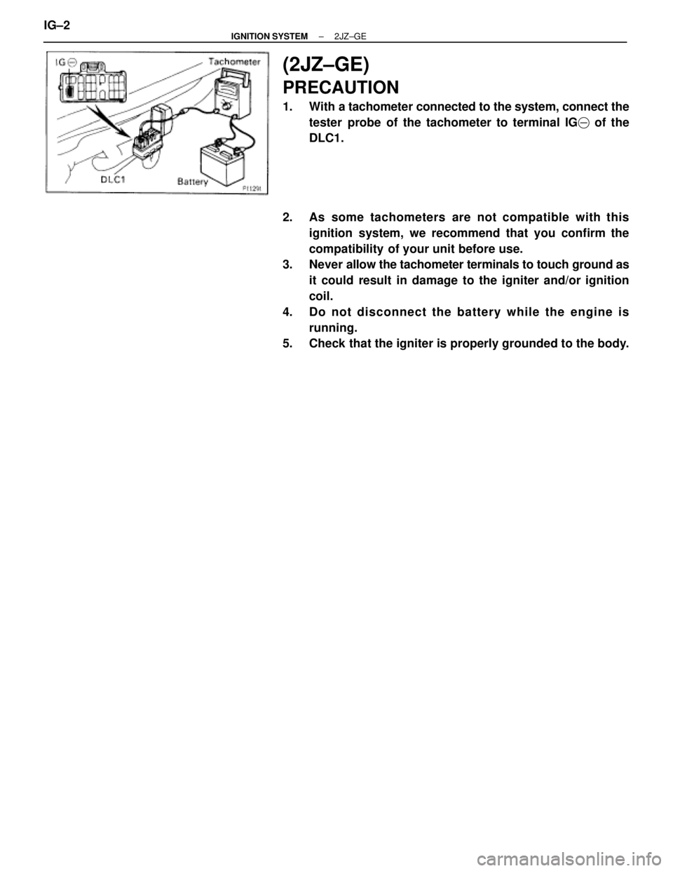
1. With a tachometer connected to the system, connect the
tester probe of the tachometer to terminal IG� of the
DLC1.
2. As some tachometers are not compatible with this
ignition system, we recommend that you confirm the
compatibility of your unit before use.
3. Never allow the tachometer terminals to touch ground as
it could result in damage to the igniter and/or ignition
coil.
4. Do not disconnect the battery while the engine is
running.
5. Check that the igniter is properly grounded to the body. IG±2
± IGNITION SYSTEM2JZ±GE
Page 1138 of 2543
PREPARATION
SST (SPECIAL SERVICE TOOLS)
09240±00020Wire Gauge SetDistributor
RECOMMENDED TOOLS
09082±00050TOYOTA Electrical Tester Set
�
09200±00010Engine Adjust Kit �
EQUIPMENT
������������������������� �������������������������Megger insulation resistance meter������������ ������������Spark plug
������������������������� �������������������������Spark plug cleaner������������ ������������
������������������������� �������������������������Thermometer������������ ������������
COOLANT
������������� �������������Item������������ ������������Capacity������������� �������������Classification
������������� �
������������ �������������Engine coolant (W/Heater) M/T
A/T������������ �
����������� ������������7.3 liters (7.7 US qts, 6.4 lmp. qts)
8.3 liters (8.8 US qts, 7.3 lmp. qts)������������� �
������������ �������������Ethylene±glycol base
± IGNITION SYSTEM2JZ±GEIG±3
Page 1139 of 2543
 Disconnect the high±tension cord (from the ignition coil) from
the distributor cap.
(b) Hold the end approx. 12.5 mm (0.50 in.) from t")
ON±VEHICLE INSPECTION
SPARK TEST
CHECK THAT SPARK OCCURS
(a) Disconnect the high±tension cord (from the ignition coil) from
the distributor cap.
(b) Hold the end approx. 12.5 mm (0.50 in.) from the body
ground.
(c) See if spark occurs while engine is being cranked.
HINT: To prevent gasoline from being injected from injectors
during this test, crank the engine for no more than 1±2 se-
conds at time.
If the spark does not occur, do the test as follows:
SPARK TEST
Connect securely.CHECK CONNECTION OF IGNITION COIL,
IGNITER AND DISTRIBUTOR CONNECTOR
CHECK RESISTANCE OF HIGH±TENSION CORD(See page IG±5)
Maximum resistance: 25 k� per cord
CHECK POWER SUPPLY TO IGNITION COIL AND
IGNITER
1. Turn ignition switch to ON.
2. Check that there is battery voltage at
ignition coil positive (+) terminal.
CHECK RESISTANCE OF IGNITION COIL(See page IG±7)Resistance: Cold Hot
Primary 0.21 ± 0.33 �0.27 ± 0.39 �
Secondary 6.4 ± 11.1 k�8.2 ± 13.0 k�
CHECK RESISTANCE OF SIGNAL GENERATOR
(PICKUP COIL)(See page IG±8)Resistance: Cold Hot
G1 and G �125 ± 200 �160 ± 235 �
G2 and G �125 ± 200 �160 ± 235 �
NE and G �155 ± 250 �190 ± 290 �
CHECK AIR GAP OF DISTRIBUTOR(See page IG±8)Air gap: 0.2 ± 0.5 mm (0.008 ± 0.020 in.)
(See page EG±413)
CHECK IGT SIGNAL FROM ECM
TRY ANOTHER IGNITER
Replace the cord(s).
Check wiring between ignition switch to ignition
coil and igniter.
Replace the ignition coil.
Replace the distributor housing assembly.
Replace the distributor housing assembly.
Check wiring between ECM, distributor and
igniter, and then try another ECM.
IG±4± IGNITION SYSTEM2JZ±GE
Page 1140 of 2543

2. REMOVE NO.3 TIMING BELT COVER
3. REMOVE CYLINDER HEAD REAR COVER
4. DISCONNECT HIGH±TENSION COR")
HIGH±TENSION CORDS INSPECTION
1. REMOVE THROTTLE BODY
(See throttle body removal in SFI System)
2. REMOVE NO.3 TIMING BELT COVER
3. REMOVE CYLINDER HEAD REAR COVER
4. DISCONNECT HIGH±TENSION CORDS FROM SPARK
PLUGS AND IGNITION COIL
Disconnect the high±tension cords at the rubber boot. Do not
pull on the high±tension cords.
NOTICE: Pulling on or bending the cords may damage the con-
ductor inside.
5. REMOVE DISTRIBUTOR CAP WITHOUT
DISCONNECTING HIGH±TENSION CORDS
6. INSPECT HIGH±TENSION CORD RESISTANCE
Using an ohmmeter, measure the resistance without discon-
necting the distributor cap.
Maximum resistance:
25 k� per cord
If the resistance is greater than maximum, check the termi-
nals. If necessary, replace the high±tension cord and/or dis-
tributor cap.
7. REINSTALL DISTRIBUTOR CAP
8. RECONNECT HIGH±TENSION CORDS TO SPARK
PLUGS AND IGNITION COIL
9. REINSTALL CYLINDER HEAD REAR COVER
10. REINSTALL NO.3 TIMING BELT COVER
11. REINSTALL THROTTLE BODY
(See throttle body installation in SFI System)
SPARK PLUGS INSPECTION
NOTICE:
wNever use a wire brush for cleaning.
wNever attempt to adjust the electrode gap on used a spark
plug.
wSpark plugs should be replaced every 100,000 km (60,000
miles).
1. DISCONNECT HIGH±TENSION CORDS FROM SPARK
PLUGS
2. INSPECT ELECTRODE
Using a megger (insulation resistance meter), measure the
insulation resistance.
Standard correct insulation resistance:
10 M� or more
If the resistance is less than specified, proceed to step 7.
HINT: If a megger is not available, the following simple meth-
od of inspection provides fairly accurate results.
± IGNITION SYSTEM(2JZ±GE)IG±5

On±Vehicle Inspection
1. C H E C K C O O L I N G FA N O P E R AT I O N W I T H L O W
TEMPERATURE (Below 88°C (190°F))
(a) Turn the ignition switch ON.
(b) Check th")