Page 2 of 2543

GENERAL DESCRIPTION
NEW AIR CONDITIONING SYSTEM WITH
HFC134a
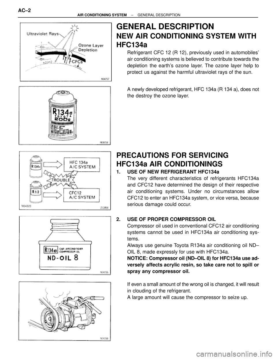
Refrigerant CFC 12 (R 12), previously used in automobiles'
air conditioning systems is believed to contribute towards the
depletion the earth's ozone layer. The ozone layer help to
protect us against the harmful ultraviolet rays of the sun.
A newly developed refrigerant, HFC 134a (R 134 a), does not
the destroy the ozone layer.
PRECAUTIONS FOR SERVICING
HFC134a AIR CONDITIONINGS
1. USE OF NEW REFRIGERANT HFC134a
The very different characteristics of refrigerants HFC134a
and CFC12 have determined the design of their respective
air conditioning systems. Under no circumstances allow
CFC12 to enter an HFC134a system, or vice versa, because
serious damage could occur.
2. USE OF PROPER COMPRESSOR OIL
Compressor oil used in conventional CFC12 air conditioning
systems cannot be used in HFC134a air conditioning sys-
tems.
Always use genuine Toyota R134a air conditioning oil ND±
OIL 8, made expressly for use with HFC134a.
NOTICE: Compressor oil (ND±OIL 8) for HFC134a use ad-
versely affects acrylic resin, so take care not to spill or
spray any compressor oil.
If even a small amount of the wrong oil is changed, it will result
in clouding of the refrigerant.
A large amount will cause the compressor to seize up. AC±2
± AIR CONDITIONING SYSTEMGENERAL DESCRIPTION
Page 171 of 2543
A340E (2JZ-GTE) AUTOMATIC TRANSMISSIONCOMPONENT PARTS REMOVAL -
AT-23
(c) Remove the race from the front planetary gear.
(d) With wooden blocks under the output shaft, stand the
transmission on the output shaft.
33. REMOVE OUTPUT SHAFT
(a) Using SST, remove the snap ring.
SST 09350-30020 (09350-07070)
HINT: Pushing the output shaft towards the front makes
it easier to remove.
(b) Remove the output shaft from the case.
34. REMOVE FRONT PLANETARY GEAR
(a) Remove the front planetary gear from the case.
(b) Remove the bearing and race from the front planetary
gear.
Page 238 of 2543
A340E (2JZ-GTE) AUTOMATIC TRANSMISSIONCOMPONENT PARTS INSTALLATION -
AT-90
(d) Face the snap ring upward (front side) and install the se-
cond brake drum to the planetary gear.
NOTICE: Face the oil hole in the drum towards the lower
side of the transmission case (the side the valve body is
installed).
(e) Align the splines of the transmission case and the as-
sembled rear planetary gear, first and reverse brake pack
and output shaft, indicated by A.
(f) Install the assembled rear planetary gear, first and re-
verse brake pack and output shaft.
(g) Rest the output shaft on wooden blocks.
(h) Using SST, install the snap ring.
SST 09350-30020 (09350-07060)
Page 245 of 2543
A340E (2JZ-GTE) AUTOMATIC TRANSMISSIONCOMPONENT PARTS INSTALLATION -
AT-97
20. INSTALL OVERDRIVE SUPPORT ASSEMBLY
(a) Coat the assembled bearing and races with petroleum jel-
ly and install them onto the overdrive support assembly.
Assembled bearing and race diameter
mm (in.)
InsideOutside
Assembled bearing
and race33.6 (1.323)50.3 (1.980)
Race37.0 (1.457)51.0 (2.008)
(b) Confirm the thrust washer is installed correctly.
HINT: Make sure that the lug shape matches the hole on
the O/D support.
(c) Using 2 bolts of SST, aim the bolt and oil holes of the over-
drive support toward the valve body side, align them with
the bolt holes of the transmission case.
SST 09350-30020 (09350-07020)
(d) Temporarily install the 2 bolts.
(e) Using SST, install the snap ring.
SST 09350-30020 (09350-07060)
(f) Install and torque the 2 bolts.
Torque: 25 N´m (260 kgf´cm, 19 ft´lbf)
Page 292 of 2543
A340E(Others) AUTOMATIC TRANSMISSIONCOMPONENT PARTS REMOVAL -
AT-35
36. REMOVE FRONT PLANETARY GEAR
(a) Using SST, remove the snap ring.
SST 09350-30029 (09350-07070)
HINT: Pushing the output shaft towards the front makes
it easier to remove.
37. REMOVE PLANETARY SUN GEAR WITH NO.1 ONE-
WAY CLUTCH
(a) Remove the planetary sun gear with No.1 one-way clutch
from the case.
(b) Remove the thrust washer.
38. CHECK PACK CLEARANCE OF SECOND BRAKE
Using a feeler gauge, measure the clearance between
the snap ring and flange.
Clearance:
0.62-1.98 mm (0.0244-0.0780 in.)
If the values are non-standard, inspect the discs.
39. REMOVE FLANGE, PLATES AND DISCS OF SECOND
BRAKE
(a) Remove the snap ring.
(b) Remove the flange, plates and discs.
Page 364 of 2543
A340E(Others) AUTOMATIC TRANSMISSIONCOMPONENT PARTS INSTALLATION -
AT-107
(d) face the snap ring upward (front side) and install the se-
cond brake drum to the planetary gear.
NOTICE: Face the oil hole in the drum towards the lower
side of the transmission case (the side the valve body is
installed).
(e) Align the splines of the transmission case and the as-
sembled rear planetary gear, first and reverse brake and
output shaft, indicated by A.
(f) Install the assembled output shaft.
(g) Rest the output shaft on wooden blocks.
(h) Using SST, install the snap ring.
SST 09350-30020 (09350-07060)
Page 372 of 2543
A340E(Others) AUTOMATIC TRANSMISSIONCOMPONENT PARTS INSTALLATION -
AT-1 15
18. INSTALL OVERDRIVE SUPPORT ASSEMBLY
(a) Coat the bearing and race with petroleum jelly and install
it onto the overdrive support assembly.
Bearing and race diameter
mm (in.)
InsideOutside
Race36.8 (1.449)50.9 (2.004)
Bearing33.6 (1.323)50.3 (1.980)
(b) Confirm the thrust washer is installed correctly.
HINT: Make sure that the lug shape matches the hole on
the O/D support.
(c) Using 2 bolts of SST, aim the bolt and oil holes of the over-
drive support toward the valve body side, and align them
with the bolt holes of the transmission case and insert.
SST 09350-30020 (09350-07020)
(d) Temporarily tighten the 2 bolts.
(e) Using SST, install the snap ring.
SST 09350-30020 (09350-07060)
HINT: Install the snap ring open end toward the valve
body.
(f) Torque the 2 bolts.
Torque: 25 N´m (260 kgf´cm, 19 ft´lbf)
Page 429 of 2543

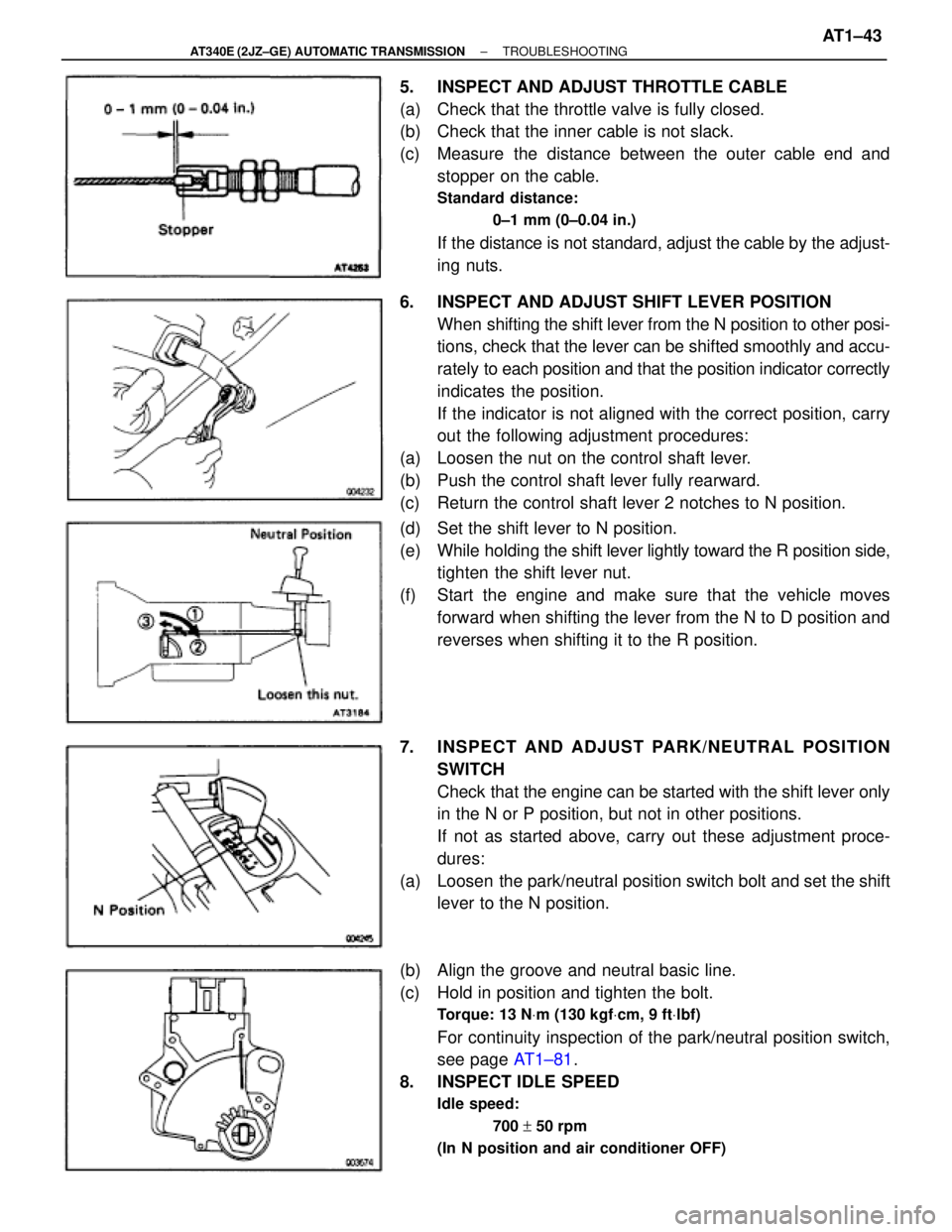
5. INSPECT AND ADJUST THROTTLE CABLE
(a) Check that the throttle valve is fully closed.
(b) Check that the inner cable is not slack.
(c) Measure the distance between the outer cable end and
stopper on the cable.
Standard distance:
0±1 mm (0±0.04 in.)
If the distance is not standard, adjust the cable by the adjust-
ing nuts.
6. INSPECT AND ADJUST SHIFT LEVER POSITION
When shifting the shift lever from the N position to other posi-
tions, check that the lever can be shifted smoothly and accu-
rately to each position and that the position indicator correctly
indicates the position.
If the indicator is not aligned with the correct position, carry
out the following adjustment procedures:
(a) Loosen the nut on the control shaft lever.
(b) Push the control shaft lever fully rearward.
(c) Return the control shaft lever 2 notches to N position.
(d) Set the shift lever to N position.
(e) While holding the shift lever lightly toward the R position side,
tighten the shift lever nut.
(f) Start the engine and make sure that the vehicle moves
forward when shifting the lever from the N to D position and
reverses when shifting it to the R position.
7. INSPECT AND ADJUST PARK/NEUTRAL POSITION
SWITCH
Check that the engine can be started with the shift lever only
in the N or P position, but not in other positions.
If not as started above, carry out these adjustment proce-
dures:
(a) Loosen the park/neutral position switch bolt and set the shift
lever to the N position.
(b) Align the groove and neutral basic line.
(c) Hold in position and tighten the bolt.
Torque: 13 NVm (130 kgfVcm, 9 ftVlbf)
For continuity inspection of the park/neutral position switch,
see page AT1±81.
8. INSPECT IDLE SPEED
Idle speed:
700 + 50 rpm
(In N position and air conditioner OFF)
± AT340E (2JZ±GE) AUTOMATIC TRANSMISSIONTROUBLESHOOTINGAT1±43