Page 1587 of 2543
IAC VALVE REMOVAL
1. DRAIN ENGINE COOLANT
2. DISCONNECT IAC VAVE CONNECTOR
3. REMOVE IAC VALVE
(a) Remove the 2 bolts, and disconnect the IAC valve from the
air intake chamber.
(b) Remove the gasket.
(c) Disconnect these hoses from the IAC valve, and remove the
IAC valve:
(1) Air hose
(2) Water bypass hose (from No.2 water bypass pipe)
(3) Water bypass hose (from No.4 water bypass pipe)
(d) Remove the seal washer and check valve.
IAC VALVE INSPECTION
INSPECT IAC VALVE OPERATION
(a) Apply battery voltage to terminals B1 and B2, and while
repeatedly grounding S1±S2±S3±S4±S 1 in sequence, and
check that the valve moves toward the closed position.
(b) Apply battery voltage to terminals B1 and B2, and while
repeatedly grounding S4±S3±S2±S1±S 4 in sequence,
check that the valve moves toward the open position.
If operation is not as specified, replace the IAC valve.
± ENGINESFI SYSTEM (2JZ±GTE)EG±297
Page 1676 of 2543
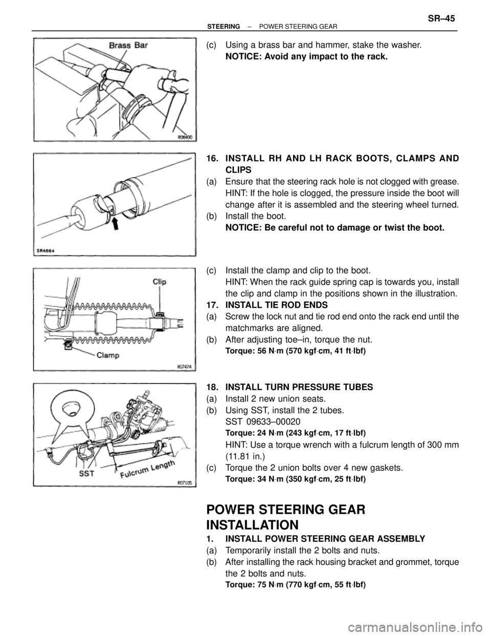
(c) Using a brass bar and hammer, stake the washer.
NOTICE: Avoid any impact to the rack.
16. INS TALL RH AND LH RACK BO O TS , CLAMP S AND
CLIPS
(a) Ensure that the steering rack hole is not clogged with grease.
HINT: If the hole is clogged, the pressure inside the boot will
change after it is assembled and the steering wheel turned.
(b) Install the boot.
NOTICE: Be careful not to damage or twist the boot.
(c) Install the clamp and clip to the boot.
HINT: When the rack guide spring cap is towards you, install
the clip and clamp in the positions shown in the illustration.
17. INSTALL TIE ROD ENDS
(a) Screw the lock nut and tie rod end onto the rack end until the
matchmarks are aligned.
(b) After adjusting toe±in, torque the nut.
Torque: 56 NVm (570 kgfVcm, 41 ftVlbf)
18. INSTALL TURN PRESSURE TUBES
(a) Install 2 new union seats.
(b) Using SST, install the 2 tubes.
SST 09633±00020
Torque: 24 NVm (243 kgfVcm, 17 ftVlbf)
HINT: Use a torque wrench with a fulcrum length of 300 mm
(11.81 in.)
(c) Torque the 2 union bolts over 4 new gaskets.
Torque: 34 NVm (350 kgfVcm, 25 ftVlbf)
POWER STEERING GEAR
INSTALLATION
1. INSTALL POWER STEERING GEAR ASSEMBLY
(a) Temporarily install the 2 bolts and nuts.
(b) After installing the rack housing bracket and grommet, torque
the 2 bolts and nuts.
Torque: 75 NVm (770 kgfVcm, 55 ftVlbf)
± STEERINGPOWER STEERING GEARSR±45
Page 1715 of 2543
1. REMOVE FRONT FENDER LINER AND HEADLIGHT
2. REMOVE FRONT AIRBAG SENSOR
(a) Disconnect the connector.
(b) Remove the bolt, the nut and the sensor.
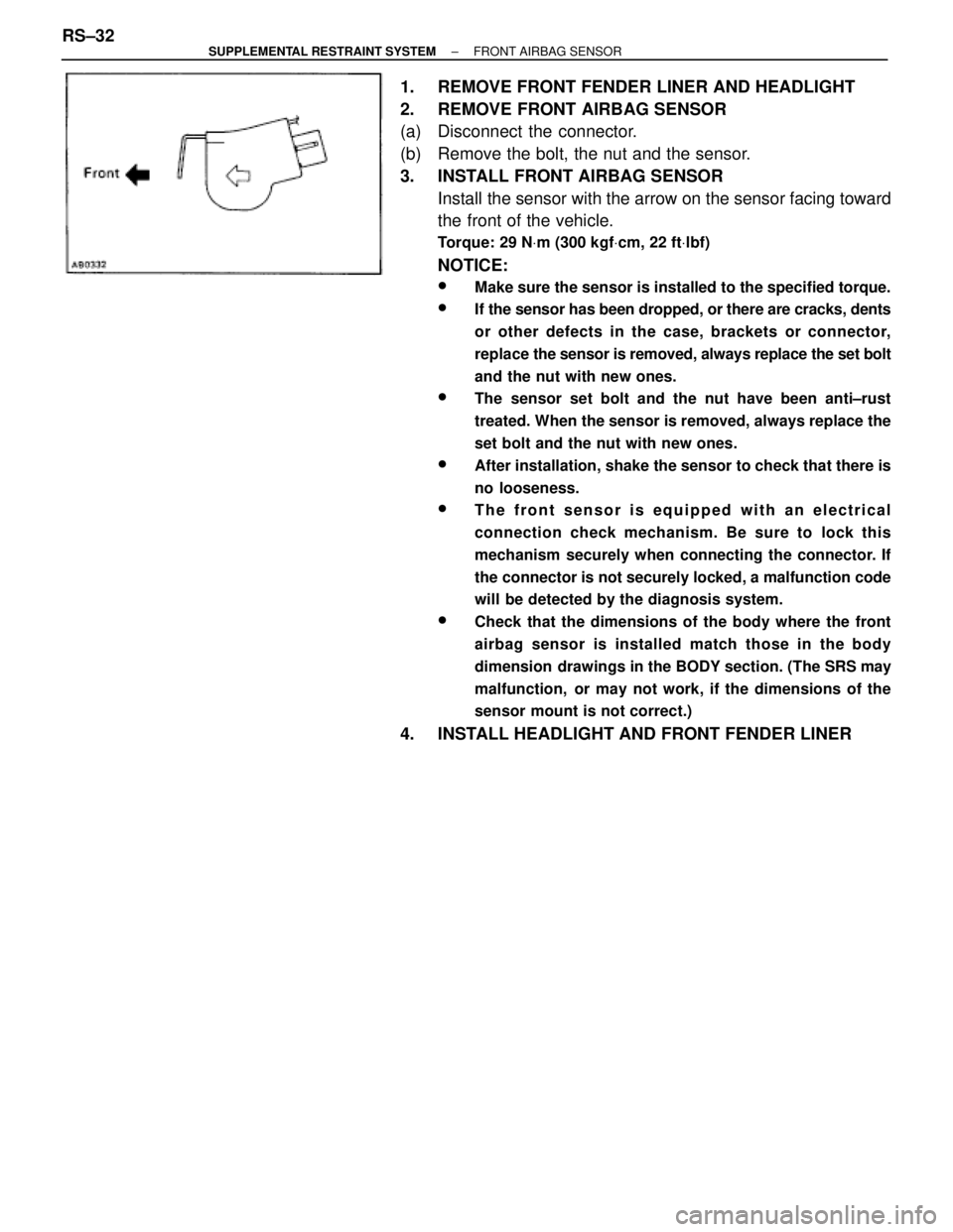
3. INSTALL FRONT AIRBAG SENSOR
Install the sensor with the arrow on the sensor facing toward
the front of the vehicle.
Torque: 29 NVm (300 kgfVcm, 22 ftVlbf)
NOTICE:
wMake sure the sensor is installed to the specified torque.
wIf the sensor has been dropped, or there are cracks, dents
or other defects in the case, brackets or connector,
replace the sensor is removed, always replace the set bolt
and the nut with new ones.
wThe sensor set bolt and the nut have been anti±rust
treated. When the sensor is removed, always replace the
set bolt and the nut with new ones.
wAfter installation, shake the sensor to check that there is
no looseness.
wThe front sensor is equipped with an electrical
connection check mechanism. Be sure to lock this
mechanism securely when connecting the connector. If
the connector is not securely locked, a malfunction code
will be detected by the diagnosis system.
wCheck that the dimensions of the body where the front
airbag sensor is installed match those in the body
dimension drawings in the BODY section. (The SRS may
malfunction, or may not work, if the dimensions of the
sensor mount is not correct.)
4. INSTALL HEADLIGHT AND FRONT FENDER LINER RS±32
± SUPPLEMENTAL RESTRAINT SYSTEMFRONT AIRBAG SENSOR
Page 1722 of 2543
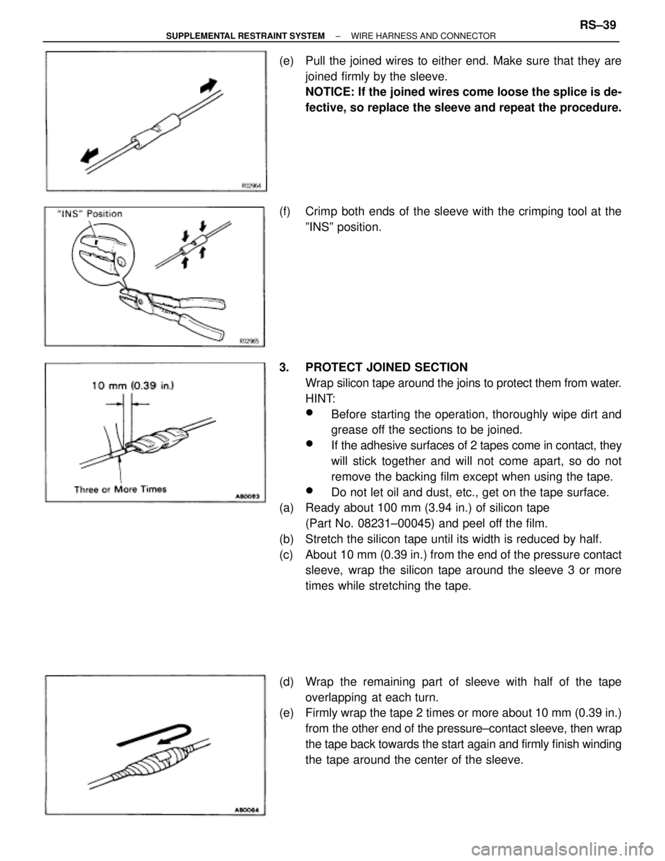
(e) Pull the joined wires to either end. Make sure that they are
joined firmly by the sleeve.
NOTICE: If the joined wires come loose the splice is de-
fective, so replace the sleeve and repeat the procedure.
(f) Crimp both ends of the sleeve with the crimping tool at the
ºINSº position.
3. PROTECT JOINED SECTION
Wrap silicon tape around the joins to protect them from water.
HINT:
wBefore starting the operation, thoroughly wipe dirt and
grease off the sections to be joined.
wIf the adhesive surfaces of 2 tapes come in contact, they
will stick together and will not come apart, so do not
remove the backing film except when using the tape.
wDo not let oil and dust, etc., get on the tape surface.
(a) Ready about 100 mm (3.94 in.) of silicon tape
(Part No. 08231±00045) and peel off the film.
(b) Stretch the silicon tape until its width is reduced by half.
(c) About 10 mm (0.39 in.) from the end of the pressure contact
sleeve, wrap the silicon tape around the sleeve 3 or more
times while stretching the tape.
(d) Wrap the remaining part of sleeve with half of the tape
overlapping at each turn.
(e) Firmly wrap the tape 2 times or more about 10 mm (0.39 in.)
from the other end of the pressure±contact sleeve, then wrap
the tape back towards the start again and firmly finish winding
the tape around the center of the sleeve.
± SUPPLEMENTAL RESTRAINT SYSTEMWIRE HARNESS AND CONNECTORRS±39
Page 1802 of 2543
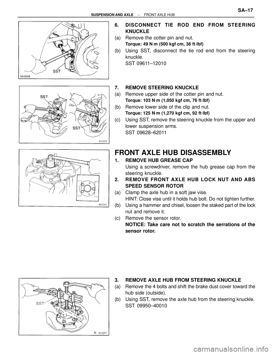
6. DISCONNECT TIE ROD END FROM STEERING
KNUCKLE
(a) Remove the cotter pin and nut.
Torque: 49 NVm (500 kgfVcm, 36 ftVlbf)
(b) Using SST, disconnect the tie rod end from the steering
knuckle.
SST 09611±12010
7. REMOVE STEERING KNUCKLE
(a) Remove upper side of the cotter pin and nut.
Torque: 103 NVm (1,050 kgfVcm, 76 ftVlbf)
(b) Remove lower side of the clip and nut.
Torque: 125 NVm (1,270 kgfVcm, 92 ftVlbf)
(c) Using SST, remove the steering knuckle from the upper and
lower suspension arms.
SST 09628±62011
FRONT AXLE HUB DISASSEMBLY
1. REMOVE HUB GREASE CAP
Using a screwdriver, remove the hub grease cap from the
steering knuckle.
2. REMOVE FRONT AXLE HUB LOCK NUT AND ABS
SPEED SENSOR ROTOR
(a) Clamp the axle hub in a soft jaw vise.
HINT: Close vise until it holds hub bolt. Do not tighten further.
(b) Using a hammer and chisel, loosen the staked part of the lock
nut and remove it.
(c) Remove the sensor rotor.
NOTICE: Take care not to scratch the serrations of the
sensor rotor.
3. REMOVE AXLE HUB FROM STEERING KNUCKLE
(a) Remove the 4 bolts and shift the brake dust cover toward the
hub side (outside).
(b) Using SST, remove the axle hub from the steering knuckle.
SST 09950±40010
± SUSPENSION AND AXLEFRONT AXLE HUBSA±17
Page 1837 of 2543
7. INSTALL NEW END COVER
(a) Pack grease into the end cover.
Grease capacity:
50±55 g (0.11±0.12 lb, 1.8±1.9 oz.)
(b) Remove grease from the surface of the inboard joint facing
the cover.
(c) Glue on a new gasket, with the side with adhesive on it facing
toward the outer race side of the inboard joint.
(d) Align the bolt holes of the cover with those of the inboard joint.
(e) Install the 6 hexagon bolts and washer from the end cover
side.
(f) Install the 6 nuts to the boot side.
(g) Using a 10 mm hexagon wrench, tighten the bolts. Do this in
the order shown, and repeat several times.
(h) Check that the claw of the end cover touches the inboard
joint.
8. CHECK DRIVE SHAFT
Check that operation of the joint is smooth within the sliding
region in the axial direction.
HINT: If a large angle is used for the cross±groove type joint,
the joint will feel like it is catching, but this does not indicate
an abnormality. SA±52
± SUSPENSION AND AXLEREAR DRIVE SHAFT
Page 1850 of 2543
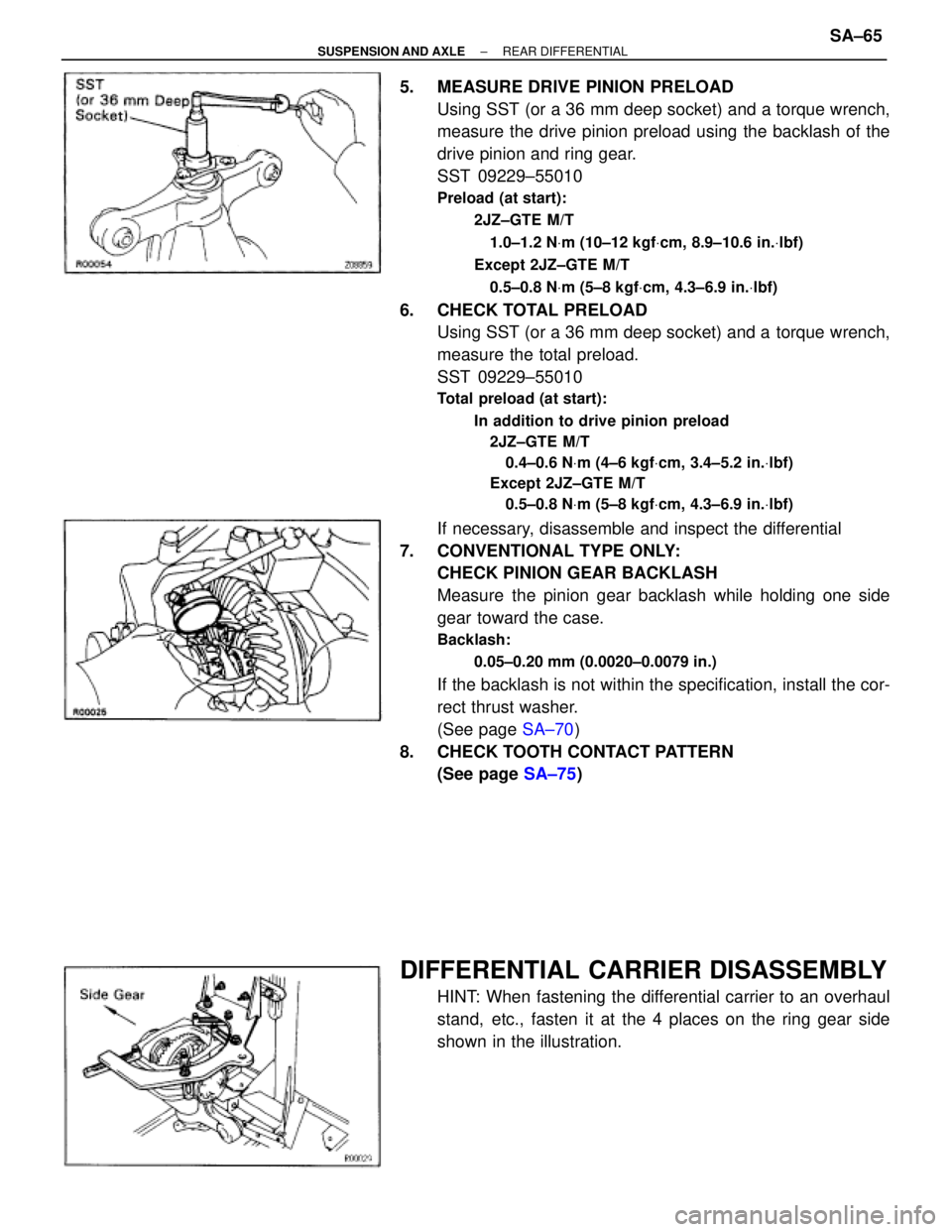
5. MEASURE DRIVE PINION PRELOAD
Using SST (or a 36 mm deep socket) and a torque wrench,
measure the drive pinion preload using the backlash of the
drive pinion and ring gear.
SST 09229±55010
Preload (at start):
2JZ±GTE M/T
1.0±1.2 NVm (10±12 kgfVcm, 8.9±10.6 in.Vlbf)
Except 2JZ±GTE M/T
0.5±0.8 NVm (5±8 kgfVcm, 4.3±6.9 in.Vlbf)
6. CHECK TOTAL PRELOAD
Using SST (or a 36 mm deep socket) and a torque wrench,
measure the total preload.
SST 09229±55010
Total preload (at start):
In addition to drive pinion preload
2JZ±GTE M/T
0.4±0.6 NVm (4±6 kgfVcm, 3.4±5.2 in.Vlbf)
Except 2JZ±GTE M/T
0.5±0.8 NVm (5±8 kgfVcm, 4.3±6.9 in.Vlbf)
If necessary, disassemble and inspect the differential
7. CONVENTIONAL TYPE ONLY:
CHECK PINION GEAR BACKLASH
Measure the pinion gear backlash while holding one side
gear toward the case.
Backlash:
0.05±0.20 mm (0.0020±0.0079 in.)
If the backlash is not within the specification, install the cor-
rect thrust washer.
(See page SA±70)
8. CHECK TOOTH CONTACT PATTERN
(See page SA±75)
DIFFERENTIAL CARRIER DISASSEMBLY
HINT: When fastening the differential carrier to an overhaul
stand, etc., fasten it at the 4 places on the ring gear side
shown in the illustration.
± SUSPENSION AND AXLEREAR DIFFERENTIALSA±65
Page 1855 of 2543
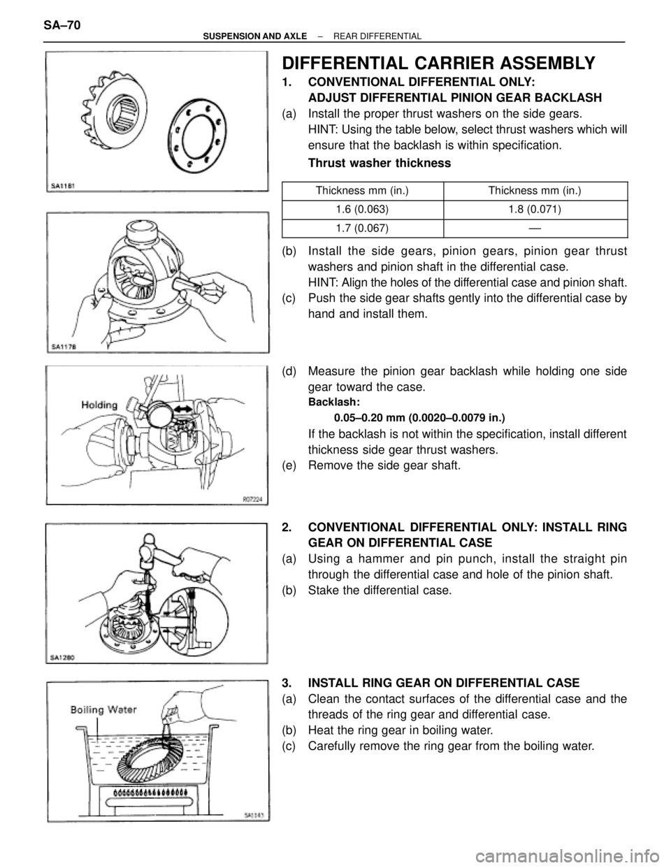
DIFFERENTIAL CARRIER ASSEMBLY
1. CONVENTIONAL DIFFERENTIAL ONLY:
ADJUST DIFFERENTIAL PINION GEAR BACKLASH
(a) Install the proper thrust washers on the side gears.
HINT: Using the table below, select thrust washers which will
ensure that the backlash is within specification.
Thrust washer thickness
����������� �����������Thickness mm (in.)������������ ������������Thickness mm (in.)����������� �
����������1.6 (0.063)������������ �
�����������1.8 (0.071)
����������� �����������1.7 (0.067)������������ ������������±±
(b) Install the side gears, pinion gears, pinion gear thrust
washers and pinion shaft in the differential case.
HINT: Align the holes of the differential case and pinion shaft.
(c) Push the side gear shafts gently into the differential case by
hand and install them.
(d) Measure the pinion gear backlash while holding one side
gear toward the case.
Backlash:
0.05±0.20 mm (0.0020±0.0079 in.)
If the backlash is not within the specification, install different
thickness side gear thrust washers.
(e) Remove the side gear shaft.
2. CONVENTIONAL DIFFERENTIAL ONLY: INSTALL RING
GEAR ON DIFFERENTIAL CASE
(a) Using a hammer and pin punch, install the straight pin
through the differential case and hole of the pinion shaft.
(b) Stake the differential case.
3. INSTALL RING GEAR ON DIFFERENTIAL CASE
(a) Clean the contact surfaces of the differential case and the
threads of the ring gear and differential case.
(b) Heat the ring gear in boiling water.
(c) Carefully remove the ring gear from the boiling water. SA±70
± SUSPENSION AND AXLEREAR DIFFERENTIAL