Page 962 of 2543
Check battery positive voltage.
Remove ABS (& TRAC) ECU with connectors still
connected.
1. Turn ignition switch ON.
2. Measure voltage between terminals IG1 and
GND of ABS (& TRAC) ECU connector.
Voltage: 10 Ð 14 V
Check and repair the charging system.
Voltage: 10 Ð 14 V
Check voltage between terminals IG1 and GND of ABS (& TRAC) ECU
connector.
Check and replace ABS (& TRAC) ECU.
INSPECTION PROCEDURE.
± BRAKE SYSTEMANTI±LOCK BRAKE SYSTEM (ABS)BR±93
Page 964 of 2543

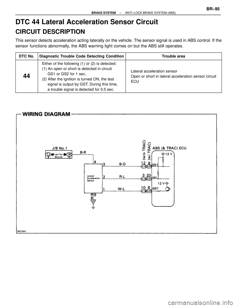
DTC 44 Lateral Acceleration Sensor Circuit
CIRCUIT DESCRIPTION
This sensor detects acceleration acting laterally on the vehicle. The sensor signal is used in ABS control. If the
sensor functions abnormally, the ABS warning light comes on but the ABS still operates.
����� �
���� �����DTC No.
���������������� �
��������������� ����������������Diagnostic Trouble Code Detecting Condition
����������������� �
���������������� �����������������Trouble area
����� �
���� �
���� �
���� �
���� �����
44
���������������� �
��������������� �
��������������� �
��������������� �
��������������� ����������������
Either of the following (1) or (2) is detected:
(1) An open or short is detected in circuit
GS1 or GS2 for 1 sec.
(2) After the ignition is turned ON, the test
signal is output by GST. During this time,
a trouble signal is detected for 0.5 sec.����������������� �
���������������� �
���������������� �
���������������� �
���������������� �����������������
� Lateral acceleration sensor
� Open or short in lateral acceleration sensor circuit
� ECU
± BRAKE SYSTEMANTI±LOCK BRAKE SYSTEM (ABS)BR±95
Page 965 of 2543
Check for open and short in harness and connector between sensor and
ECU (See page IN±30).
1. Remove ABS (& TRAC) ECU with connec±
tors still connected.
1. Disconnect sensor connector.
3. Turn ignition switch ON.
Measure voltage between terminals GS1, GS2,
GST of ECU and body ground.
Voltage:
GS1, GS2: 10 Ð 14 V
GST: As shown below
Check voltage between terminals GS1, GS2, GST of ECU and body ground.
Repair or replace harness or connector.
Check and replace ABS (& TRAC) ECU.
Check and replace lateral acceleration sensor.
INSPECTION PROCEDURE.
BR±96± BRAKE SYSTEMANTI±LOCK BRAKE SYSTEM (ABS)
Page 972 of 2543
Check voltage between terminals THFA, TRCO of ABS & TRAC ECU and
body ground.
Check and replace ABS & TRAC ECU.
Disconnect ABS & TRAC ECU connector.
Measure voltage between terminals THFA, TRCO
of ABS & TRAC ECU connector and body ground
when ignition switch is turned ON.
Voltage: See step 1.
Check voltage between terminals THFA, TRCO of ABS & TRAC ECU and
body ground with ABS & TRAC ECU connector is disconnected.
Remove ABS & TRAC ECU with connectors still
connected.
Measure voltage between terminals THFA,
TRCO of ABS & TRAC ECU and body ground
when ignition switch is turned ON.
Voltage:
TRCO: 7 Ð 12 V
THFA: About 5 V (Pulse)
Check and replace ABS & TRAC ECU.
Check for open and short in harness and connector between ABS & TRAC
ECU and TRAC ECU (See page IN±30).
Check and replace or connector.
Check and replace TRAC ECU.
INSPECTION PROCEDURE.
± BRAKE SYSTEMANTI±LOCK BRAKE SYSTEM (ABS)BR±103
Page 982 of 2543
Check for open and short in harness and connector of systems connected
to Tc terminal (See page IN±30).
Turn ignition switch ON.
Measure voltage between terminals Tc and E1 of DLC2
or DLC1.
Voltage: 10 ± 14 V
If ABS warning light does not blink even
after Tc and E1 are connected, the ECU may
be defective.
Repair or replace harness or connector.
Check or replace ABS (& TRAC) ECU.
INSPECTION PROCEDURE.
± BRAKE SYSTEMANTI±LOCK BRAKE SYSTEM (ABS)BR±113
Page 983 of 2543
Ts Terminal Circuit
CIRCUIT DESCRIPTION
The sensor check circuit detects abnormalities in the speed sensor signal which cannot be detected with the
diagnostic trouble code check.
Connecting terminals Ts and E1 of the DLC1 in the engine compartment starts the check.
Check for open and short in harness and connector between ABS (&TRAC)
ECU and DLC1, DLC1 and body ground (See page IN±30).
Turn ignition switch ON.
Measure voltage between terminals Ts and E1 of
DLC1.
Voltage: 10 ± 14 V
If ABS warning light does not blink even
after Ts and E1 are connected, the ECU may
be defective.
Repair or replace harness or connector.
Check and replace ABS (& TRAC) ECU.
INSPECTION PROCEDURE.
BR±114± BRAKE SYSTEMANTI±LOCK BRAKE SYSTEM (ABS)
Page 995 of 2543

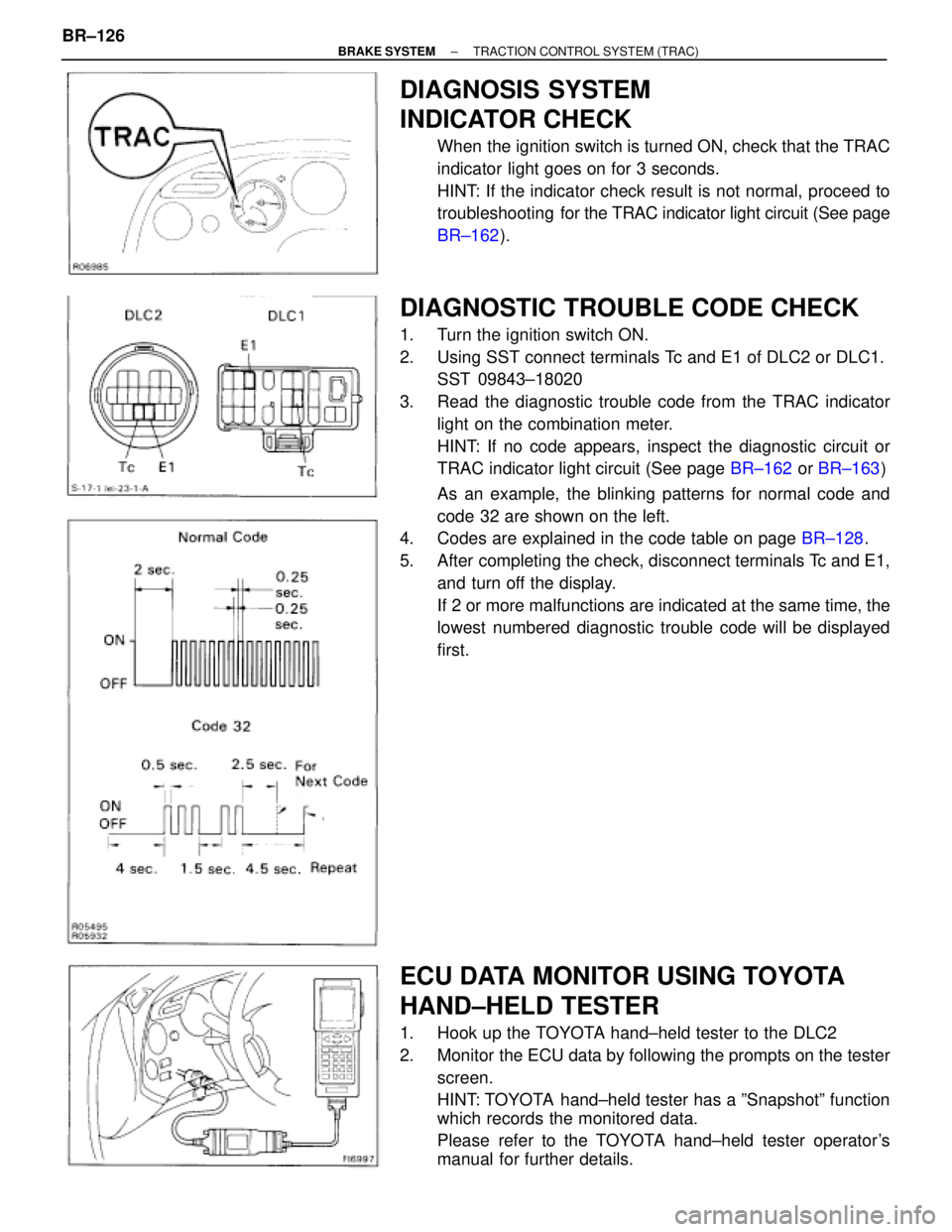
DIAGNOSIS SYSTEM
INDICATOR CHECK
When the ignition switch is turned ON, check that the TRAC
indicator light goes on for 3 seconds.
HINT: If the indicator check result is not normal, proceed to
troubleshooting for the TRAC indicator light circuit (See page
BR±162).
DIAGNOSTIC TROUBLE CODE CHECK
1. Turn the ignition switch ON.
2. Using SST connect terminals Tc and E1 of DLC2 or DLC1.
SST 09843±18020
3. Read the diagnostic trouble code from the TRAC indicator
light on the combination meter.
HINT: If no code appears, inspect the diagnostic circuit or
TRAC indicator light circuit (See page BR±162 or BR±163)
As an example, the blinking patterns for normal code and
code 32 are shown on the left.
4. Codes are explained in the code table on page BR±128.
5. After completing the check, disconnect terminals Tc and E1,
and turn off the display.
If 2 or more malfunctions are indicated at the same time, the
lowest numbered diagnostic trouble code will be displayed
first.
ECU DATA MONITOR USING TOYOTA
HAND±HELD TESTER
1. Hook up the TOYOTA hand±held tester to the DLC2
2. Monitor the ECU data by following the prompts on the tester
screen.
HINT: TOYOTA hand±held tester has a ºSnapshotº function
which records the monitored data.
Please refer to the TOYOTA hand±held tester operator's
manual for further details. BR±126
± BRAKE SYSTEMTRACTION CONTROL SYSTEM (TRAC)
Page 1007 of 2543

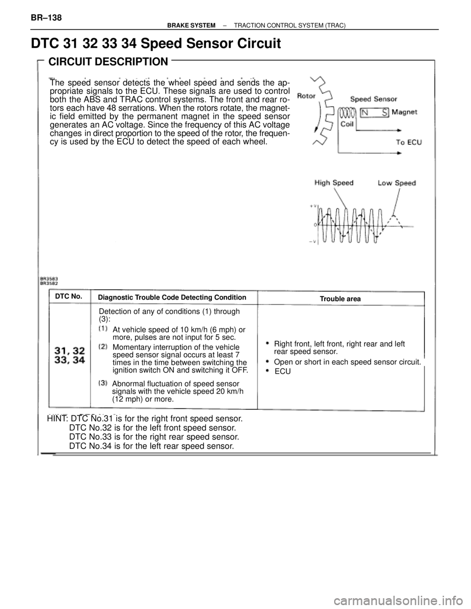
DTC 31 32 33 34 Speed Sensor Circuit
HINT: DTC No.31 is for the right front speed sensor.
DTC No.32 is for the left front speed sensor.
DTC No.33 is for the right rear speed sensor.
DTC No.34 is for the left rear speed sensor.
CIRCUIT DESCRIPTION
The speed sensor detects the wheel speed and sends the ap-
propriate signals to the ECU. These signals are used to control
both the ABS and TRAC control systems. The front and rear ro-
tors each have 48 serrations. When the rotors rotate, the magnet-
ic field emitted by the permanent magnet in the speed sensor
generates an AC voltage. Since the frequency of this AC voltage
changes in direct proportion to the speed of the rotor, the frequen-
cy is used by the ECU to detect the speed of each wheel.
Diagnostic Trouble Code Detecting ConditionTrouble areaDTC No.
Detection of any of conditions (1) through
(3):
At vehicle speed of 10 km/h (6 mph) or
more, pulses are not input for 5 sec.
Momentary interruption of the vehicle
speed sensor signal occurs at least 7
times in the time between switching the
ignition switch ON and switching it OFF.
Abnormal fluctuation of speed sensor
signals with the vehicle speed 20 km/h
(12 mph) or more.
Right front, left front, right rear and left
rear speed sensor.
Open or short in each speed sensor circuit.
ECU
BR±138± BRAKE SYSTEMTRACTION CONTROL SYSTEM (TRAC)