Page 767 of 2543
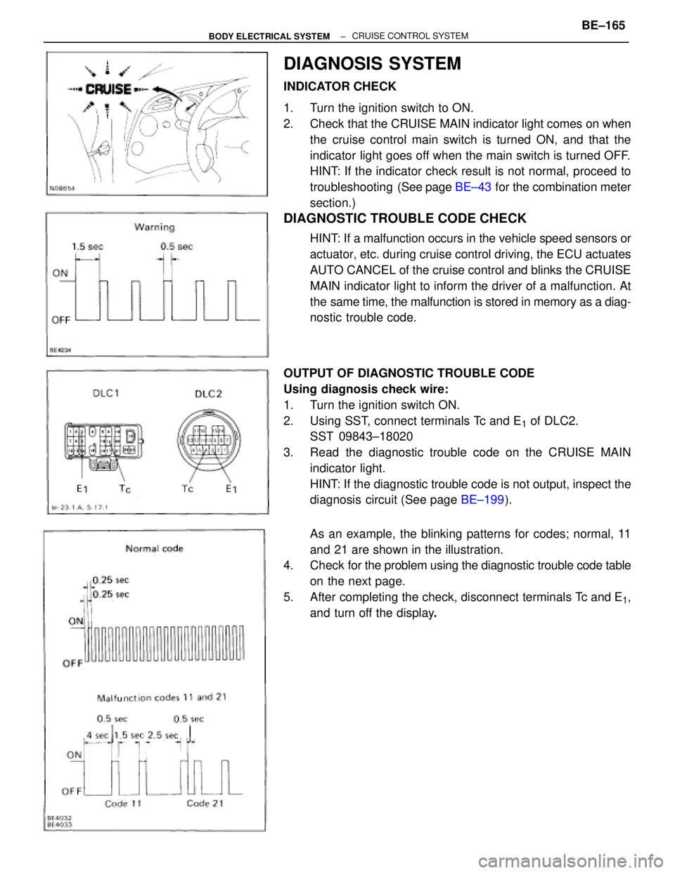
DIAGNOSIS SYSTEM
INDICATOR CHECK
1. Turn the ignition switch to ON.
2. Check that the CRUISE MAIN indicator light comes on when
the cruise control main switch is turned ON, and that the
indicator light goes off when the main switch is turned OFF.
HINT: If the indicator check result is not normal, proceed to
troubleshooting (See page BE±43 for the combination meter
section.)
DIAGNOSTIC TROUBLE CODE CHECK
HINT: If a malfunction occurs in the vehicle speed sensors or
actuator, etc. during cruise control driving, the ECU actuates
AUTO CANCEL of the cruise control and blinks the CRUISE
MAIN indicator light to inform the driver of a malfunction. At
the same time, the malfunction is stored in memory as a diag-
nostic trouble code.
OUTPUT OF DIAGNOSTIC TROUBLE CODE
Using diagnosis check wire:
1. Turn the ignition switch ON.
2. Using SST, connect terminals Tc and E
1 of DLC2.
SST 09843±18020
3. Read the diagnostic trouble code on the CRUISE MAIN
indicator light.
HINT: If the diagnostic trouble code is not output, inspect the
diagnosis circuit (See page BE±199).
As an example, the blinking patterns for codes; normal, 11
and 21 are shown in the illustration.
4. Check for the problem using the diagnostic trouble code table
on the next page.
5. After completing the check, disconnect terminals Tc and E
1,
and turn off the display.
± BODY ELECTRICAL SYSTEMBE±165CRUISE CONTROL SYSTEM
Page 770 of 2543
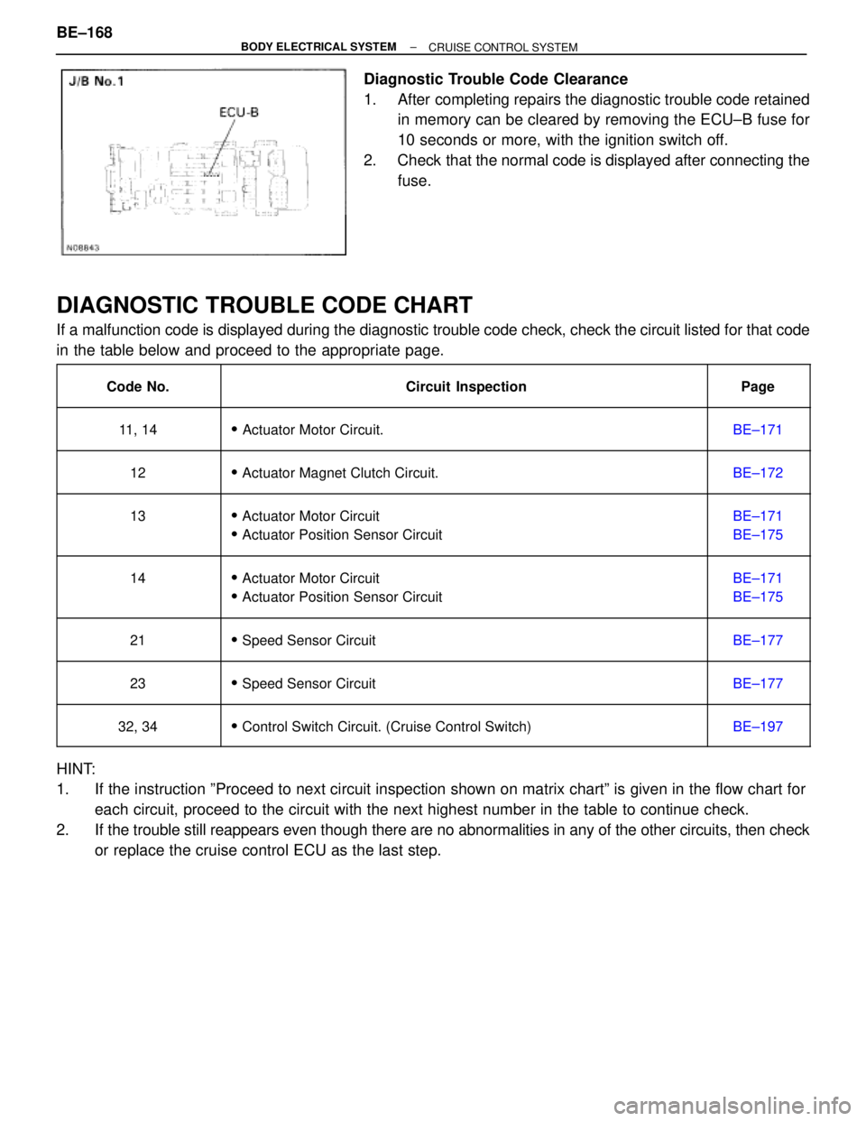
Diagnostic Trouble Code Clearance
1. After completing repairs the diagnostic trouble code retained
in memory can be cleared by removing the ECU±B fuse for
10 seconds or more, with the ignition switch off.
2. Check that the normal code is displayed after connecting the
fuse.
DIAGNOSTIC TROUBLE CODE CHART
If a malfunction code is displayed during the diagnostic trouble code check, check the circuit listed for that code
in the table below and proceed to the appropriate page.
��������� �
�������� ���������Code No.
����������������������� �
���������������������� �����������������������Circuit Inspection
������ �
����� ������Page
��������� �
�������� ���������11, 14
����������������������� �
���������������������� ������������������������ Actuator Motor Circuit.
������ �
����� ������BE±171
��������� �
�������� ���������12
����������������������� �
���������������������� ������������������������ Actuator Magnet Clutch Circuit.
������ �
����� ������BE±172
��������� �
�������� �
�������� ���������
13
����������������������� �
���������������������� �
���������������������� �����������������������
� Actuator Motor Circuit
� Actuator Position Sensor Circuit
������ �
����� �
����� ������
BE±171
BE±175
��������� �
�������� �
�������� ���������
14
����������������������� �
���������������������� �
���������������������� �����������������������
� Actuator Motor Circuit
� Actuator Position Sensor Circuit
������ �
����� �
����� ������
BE±171
BE±175
��������� �
�������� ���������21
����������������������� �
���������������������� ������������������������ Speed Sensor Circuit
������ �
����� ������BE±177
��������� �
�������� ���������23
����������������������� �
���������������������� ������������������������ Speed Sensor Circuit
������ �
����� ������BE±177
��������� �
�������� ���������32, 34����������������������� �
���������������������� ������������������������ Control Switch Circuit. (Cruise Control Switch)������ �
����� ������BE±197
HINT:
1. If the instruction ºProceed to next circuit inspection shown on matrix chartº is given in the flow chart for
each circuit, proceed to the circuit with the next highest number in the table to continue check.
2. If the trouble still reappears even though there are no abnormalities in any of the other circuits, then check
or replace the cruise control ECU as the last step. BE±168
± BODY ELECTRICAL SYSTEM
CRUISE CONTROL SYSTEM
Page 771 of 2543
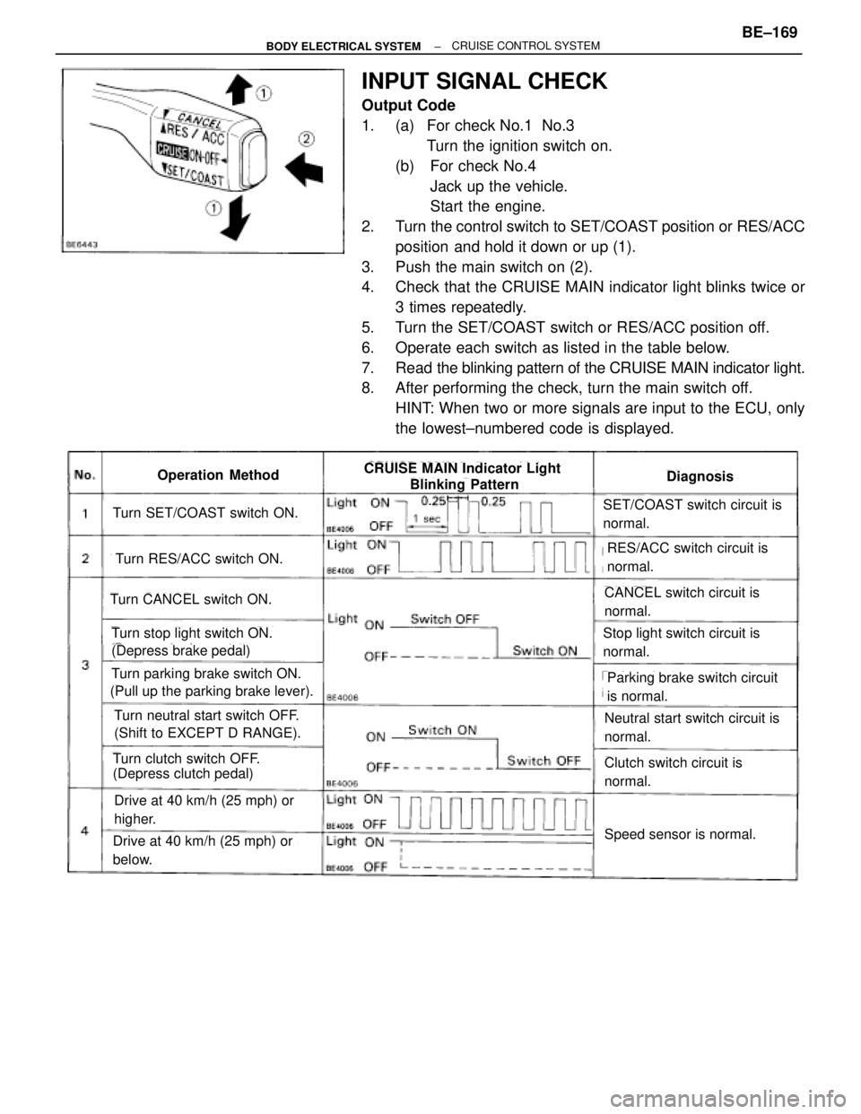
INPUT SIGNAL CHECK
Output Code
1. (a) For check No.1 No.3
Turn the ignition switch on.
(b) For check No.4
Jack up the vehicle.
Start the engine.
2. Turn the control switch to SET/COAST position or RES/ACC
position and hold it down or up (1).
3. Push the main switch on (2).
4. Check that the CRUISE MAIN indicator light blinks twice or
3 times repeatedly.
5. Turn the SET/COAST switch or RES/ACC position off.
6. Operate each switch as listed in the table below.
7. Read the blinking pattern of the CRUISE MAIN indicator light.
8. After performing the check, turn the main switch off.
HINT: When two or more signals are input to the ECU, only
the lowest±numbered code is displayed.
Turn SET/COAST switch ON.
Turn RES/ACC switch ON.
Turn CANCEL switch ON.
Turn stop light switch ON.
(Depress brake pedal)
Turn parking brake switch ON.
(Pull up the parking brake lever).
Turn neutral start switch OFF.
(Shift to EXCEPT D RANGE).
Turn clutch switch OFF.
(Depress clutch pedal)
Drive at 40 km/h (25 mph) or
higher.
Drive at 40 km/h (25 mph) or
below.
SET/COAST switch circuit is
normal.
RES/ACC switch circuit is
normal.
CANCEL switch circuit is
normal.
Stop light switch circuit is
normal.
Parking brake switch circuit
is normal.
Neutral start switch circuit is
normal.
Clutch switch circuit is
normal.
Speed sensor is normal.
DiagnosisOperation MethodCRUISE MAIN Indicator Light
Blinking Pattern
± BODY ELECTRICAL SYSTEMBE±169CRUISE CONTROL SYSTEM
Page 778 of 2543
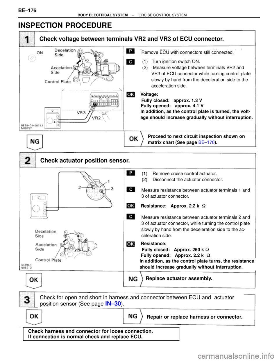
Repair or replace harness or connector.
Check for open and short in harness and connector between ECU and actuator
position sensor (See page
IN±30).
(1) Turn ignition switch ON.
(2) Measure voltage between terminals VR2 and
VR3 of ECU connector while turning control plate
slowly by hand from the deceleration side to the
acceleration side.
Voltage:
Check actuator position sensor.
Replace actuator assembly.Replace actuator assembly.
Check voltage between terminals VR2 and VR3 of ECU connector.
Fully closed: approx. 1.3 V
Fully opened: approx. 4.1 V
In addition, as the control plate is turned, the volt-
age should increase gradually without interruption.
Remove ECU with connectors still connected.
Proceed to next circuit inspection shown on
matrix chart (See page BE±170).
Resistance:
Fully closed: Approx. 260 k �
In addition, as the control plate turns, the resistance
should increase gradually without interruption.
Fully opened: Approx. 2.2 k �
Measure resistance between actuator terminals 1 and
3 of actuator connector.
Resistance: Approx. 2.2 k �
Measure resistance between actuator terminals 2 and
3 of actuator connector, while turning the control plate
slowly by hand from the deceleration side to the ac-
celeration side.
(1) Remove cruise control actuator.
(2) Disconnect the actuator connector.
INSPECTION PROCEDURE
����������������������� �
���������������������� �����������������������Check harness and connector for loose connection.
If connection is normal check and replace ECU.
BE±176± BODY ELECTRICAL SYSTEMCRUISE CONTROL SYSTEM
Page 782 of 2543
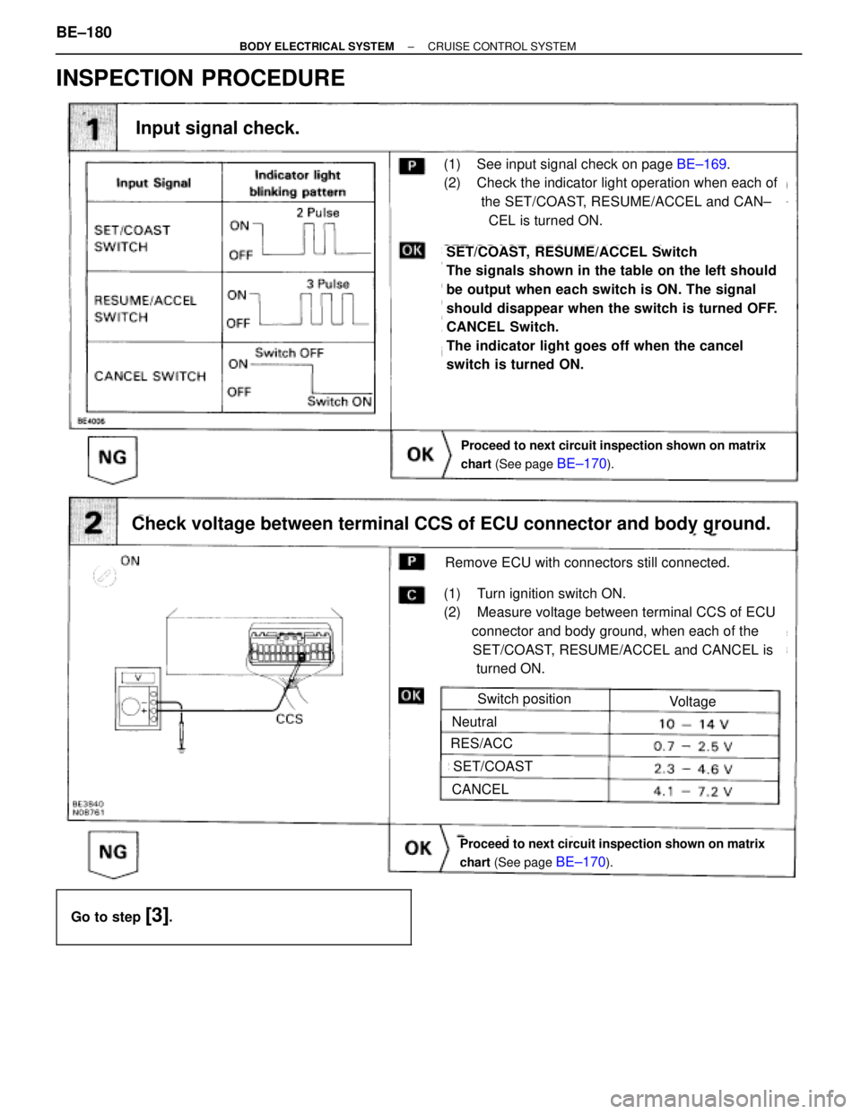
INSPECTION PROCEDURE
Proceed to next circuit inspection shown on matrix
chart (See page
BE±170).
(1) See input signal check on page BE±169.
(2) Check the indicator light operation when each of
the SET/COAST, RESUME/ACCEL and CAN±
CEL is turned ON.
Input signal check.
SET/COAST, RESUME/ACCEL Switch
The signals shown in the table on the left should
be output when each switch is ON. The signal
should disappear when the switch is turned OFF.
CANCEL Switch.
The indicator light goes off when the cancel
switch is turned ON.
Check voltage between terminal CCS of ECU connector and body ground.
Proceed to next circuit inspection shown on matrix
chart (See page
BE±170).
(1) Turn ignition switch ON.
(2) Measure voltage between terminal CCS of ECU
connector and body ground, when each of the
SET/COAST, RESUME/ACCEL and CANCEL is
turned ON.
Remove ECU with connectors still connected.
Switch position
Neutral
RES/ACC
SET/COAST
CANCEL
Voltage
����������������� �
����������������
�����������������
Go to step [3].
BE±180± BODY ELECTRICAL SYSTEMCRUISE CONTROL SYSTEM
Page 785 of 2543
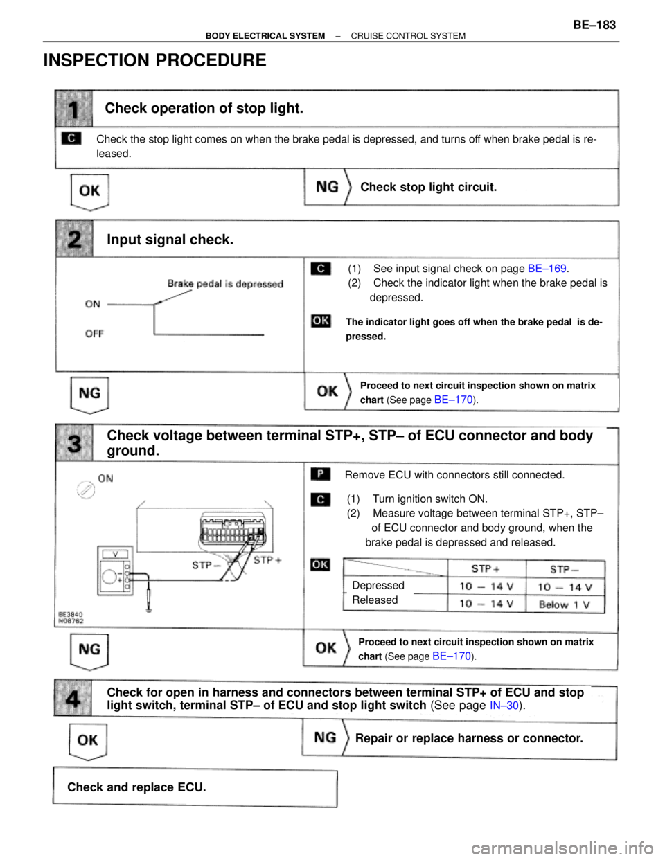
chart (See page BE±170).
Proceed to next circuit inspection shown on matrix
chart (See page
BE±170).
(1) See input signal check on page BE±169.
(2) Check the indicator light when the brake pedal is
depressed.
Check operation of stop light.
Check voltage between terminal STP+, STP± of ECU connector and body
ground.
(1) Turn ignition switch ON.
(2) Measure voltage between terminal STP+, STP±
of ECU connector and body ground, when the
brake pedal is depressed and released.
Remove ECU with connectors still connected.
Input signal check.
Proceed to next circuit inspection shown on matrix
chart (See page
BE±170).
The indicator light goes off when the brake pedal is de-
pressed.
Check the stop light comes on when the brake pedal is depressed, and turns off when brake pedal is re-
leased.
Check stop light circuit.
Repair or replace harness or connector.
Check and replace ECU.
Check for open in harness and connectors between terminal STP+ of ECU and stop
light switch, terminal STP± of ECU and stop light switch (See page
IN±30).
Depressed
Released
INSPECTION PROCEDURE
± BODY ELECTRICAL SYSTEMCRUISE CONTROL SYSTEMBE±183
Page 787 of 2543
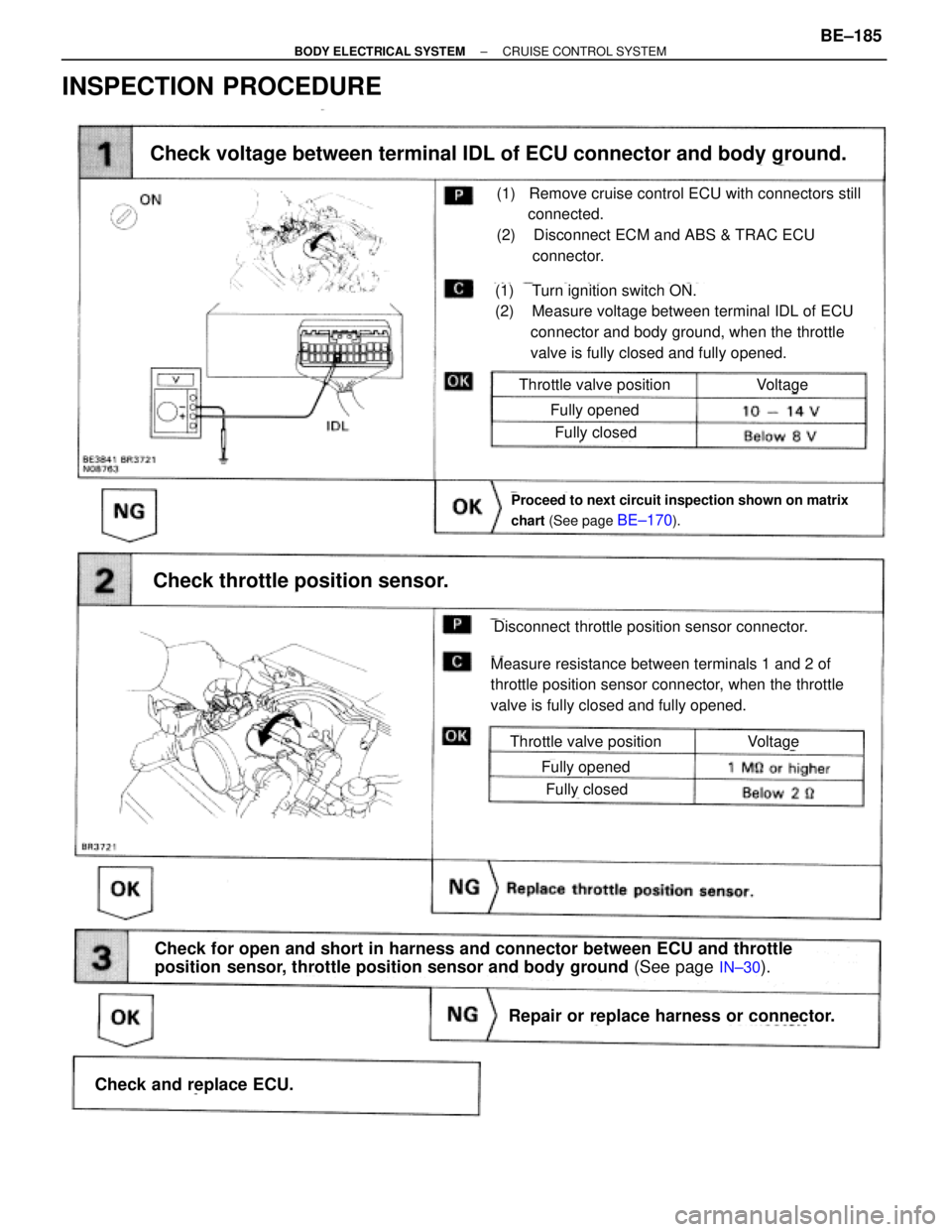
INSPECTION PROCEDURE
Proceed to next circuit inspection shown on matrix
chart (See page
BE±170).
(1) Turn ignition switch ON.
(2) Measure voltage between terminal IDL of ECU
connector and body ground, when the throttle
valve is fully closed and fully opened.
Check voltage between terminal IDL of ECU connector and body ground.
Check throttle position sensor.
Measure resistance between terminals 1 and 2 of
throttle position sensor connector, when the throttle
valve is fully closed and fully opened.
(1) Remove cruise control ECU with connectors still
connected.
(2) Disconnect ECM and ABS & TRAC ECU
connector.
Disconnect throttle position sensor connector.
Throttle valve position
Fully opened
Fully closed
Voltage
Throttle valve position
Fully opened
Fully closed
Voltage
Repair or replace harness or connector.
Check and replace ECU.
Check for open and short in harness and connector between ECU and throttle
position sensor, throttle position sensor and body ground (See page
IN±30).
± BODY ELECTRICAL SYSTEMCRUISE CONTROL SYSTEMBE±185
Page 789 of 2543
INSPECTION PROCEDURE
(1) Disconnect ECU connector.
(2) Turn ignition switch ON.
(3) Measure voltage between terminal OD of har±
ness side connector of ECU and body ground.
Check voltage between terminal OD of harness side connector ECU and
body ground.
Check operation of overdrive.
Remove ECU with connector still connected.
Check and Repair Electronically controlled transmis-
sion (See AT section).
Voltage: 10 ± 14 V
Go to step
Go to step
Test drive after engine warm up.
Check that overdrive ON e OFF occurs with operation of OD switch ON±OFF.
± BODY ELECTRICAL SYSTEMCRUISE CONTROL SYSTEMBE±187