Page 1759 of 2543
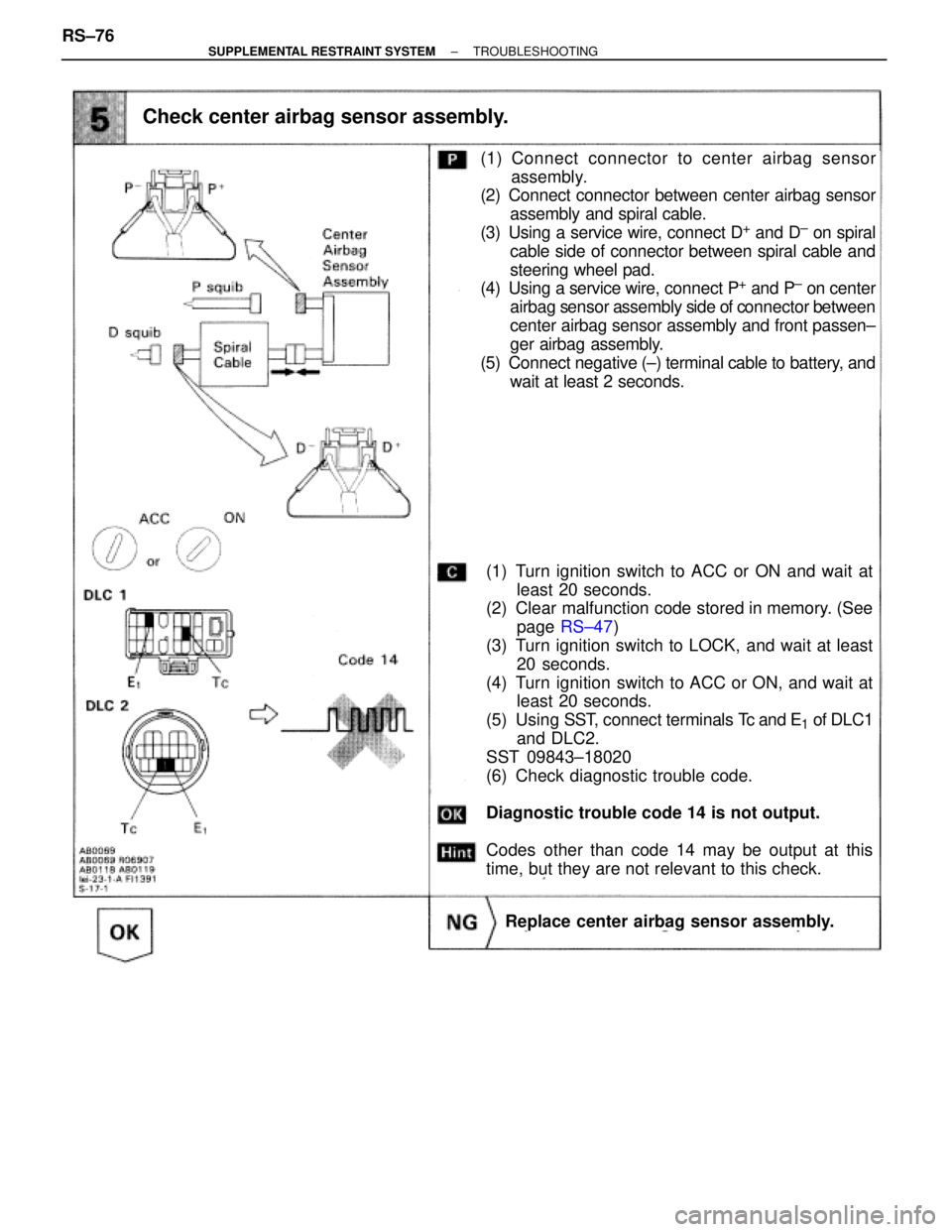
Check center airbag sensor assembly.
(1) Turn ignition switch to ACC or ON and wait at
least 20 seconds.
(2) Clear malfunction code stored in memory. (See
page RS±47)
(3) Turn ignition switch to LOCK, and wait at least
20 seconds.
(4) Turn ignition switch to ACC or ON, and wait at
least 20 seconds.
(5) Using SST, connect terminals Tc and E
1 of DLC1
and DLC2.
SST 09843±18020
(6) Check diagnostic trouble code.
Diagnostic trouble code 14 is not output.
Codes other than code 14 may be output at this
time, but they are not relevant to this check.
Replace center airbag sensor assembly.
(1) Connect connector to center airbag sensor
assembly.
(2) Connect connector between center airbag sensor
assembly and spiral cable.
(3) Using a service wire, connect D
+ and D± on spiral
cable side of connector between spiral cable and
steering wheel pad.
(4) Using a service wire, connect P
+ and P± on center
airbag sensor assembly side of connector between
center airbag sensor assembly and front passen±
ger airbag assembly.
(5) Connect negative (±) terminal cable to battery, and
wait at least 2 seconds. RS±76
± SUPPLEMENTAL RESTRAINT SYSTEMTROUBLESHOOTING
Page 1760 of 2543
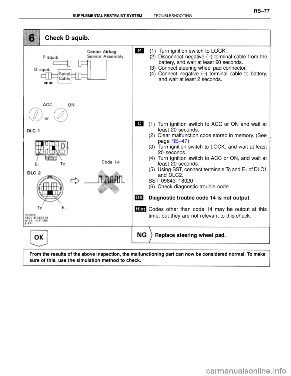
From the results of the above inspection, the malfunctioning part can now be considered normal. To make
sure of this, use the simulation method to check.
Check D squib.
(1) Turn ignition switch to ACC or ON and wait at
least 20 seconds.
(2) Clear malfunction code stored in memory. (See
page RS±47)
(3) Turn ignition switch to LOCK, and wait at least
20 seconds.
(4) Turn ignition switch to ACC or ON, and wait at
least 20 seconds.
(5) Using SST, connect terminals Tc and E
1 of DLC1
and DLC2.
SST 09843±18020
(6) Check diagnostic trouble code.
Diagnostic trouble code 14 is not output.
Codes other than code 14 may be output at this
time, but they are not relevant to this check.
(1) Turn ignition switch to LOCK.
(2) Disconnect negative (±) terminal cable from the
battery, and wait at least 90 seconds.
(3) Connect steering wheel pad connector.
(4) Connect negative (±) terminal cable to battery,
and wait at least 2 seconds.
Replace steering wheel pad.
± SUPPLEMENTAL RESTRAINT SYSTEMTROUBLESHOOTINGRS±77
Page 1763 of 2543
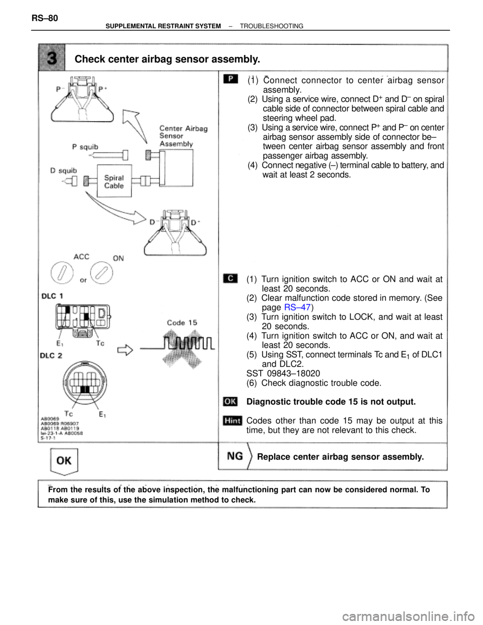
Check center airbag sensor assembly.
(1) Turn ignition switch to ACC or ON and wait at
least 20 seconds.
(2) Clear malfunction code stored in memory. (See
page RS±47)
(3) Turn ignition switch to LOCK, and wait at least
20 seconds.
(4) Turn ignition switch to ACC or ON, and wait at
least 20 seconds.
(5) Using SST, connect terminals Tc and E
1 of DLC1
and DLC2.
SST 09843±18020
(6) Check diagnostic trouble code.
Diagnostic trouble code 15 is not output.
Codes other than code 15 may be output at this
time, but they are not relevant to this check.
Replace center airbag sensor assembly.
(1) Connect connector to center airbag sensor
assembly.
(2) Using a service wire, connect D
+ and D± on spiral
cable side of connector between spiral cable and
steering wheel pad.
(3) Using a service wire, connect P
+ and P± on center
airbag sensor assembly side of connector be±
tween center airbag sensor assembly and front
passenger airbag assembly.
(4) Connect negative (±) terminal cable to battery, and
wait at least 2 seconds.
From the results of the above inspection, the malfunctioning part can now be considered normal. To
make sure of this, use the simulation method to check.
RS±80± SUPPLEMENTAL RESTRAINT SYSTEMTROUBLESHOOTING
Page 1765 of 2543
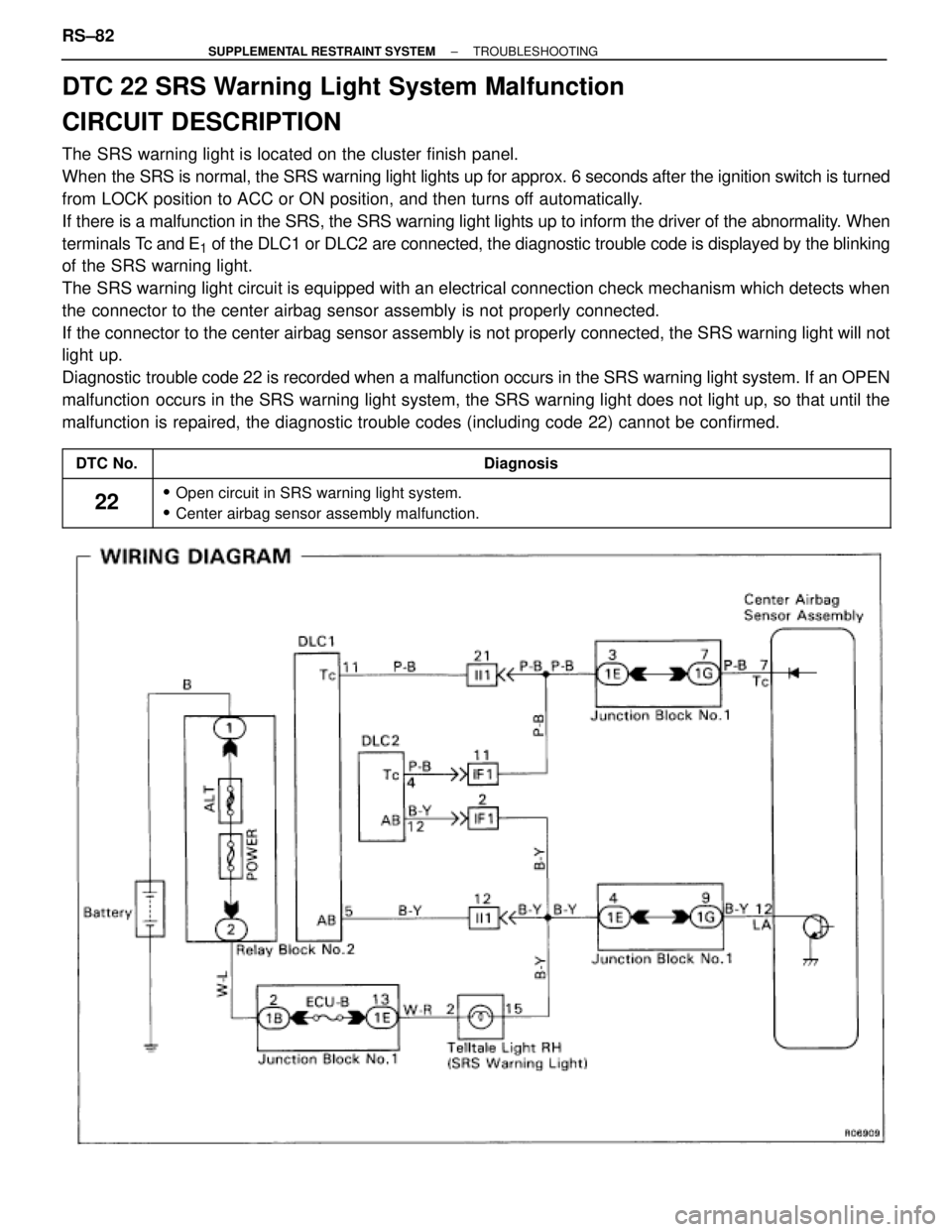
DTC 22 SRS Warning Light System Malfunction
CIRCUIT DESCRIPTION
The SRS warning light is located on the cluster finish panel.
When the SRS is normal, the SRS warning light lights up for approx. 6 seconds after the ignition switch is turned
from LOCK position to ACC or ON position, and then turns off automatically.
If there is a malfunction in the SRS, the SRS warning light lights up to inform the driver of the abnormality. When
terminals Tc and E
1 of the DLC1 or DLC2 are connected, the diagnostic trouble code is displayed by the blinking
of the SRS warning light.
The SRS warning light circuit is equipped with an electrical connection check mechanism which detects when
the connector to the center airbag sensor assembly is not properly connected.
If the connector to the center airbag sensor assembly is not properly connected, the SRS warning light will not
light up.
Diagnostic trouble code 22 is recorded when a malfunction occurs in the SRS warning light system. If an OPEN
malfunction occurs in the SRS warning light system, the SRS warning light does not light up, so that until the
malfunction is repaired, the diagnostic trouble codes (including code 22) cannot be confirmed.
����� �
����DTC No.�������������������������������� �
�������������������������������Diagnosis����� �
���� �
���� �����
22
�������������������������������� �
������������������������������� �
������������������������������� ��������������������������������
� Open circuit in SRS warning light system.
� Center airbag sensor assembly malfunction.
RS±82± SUPPLEMENTAL RESTRAINT SYSTEMTROUBLESHOOTING
Page 1767 of 2543
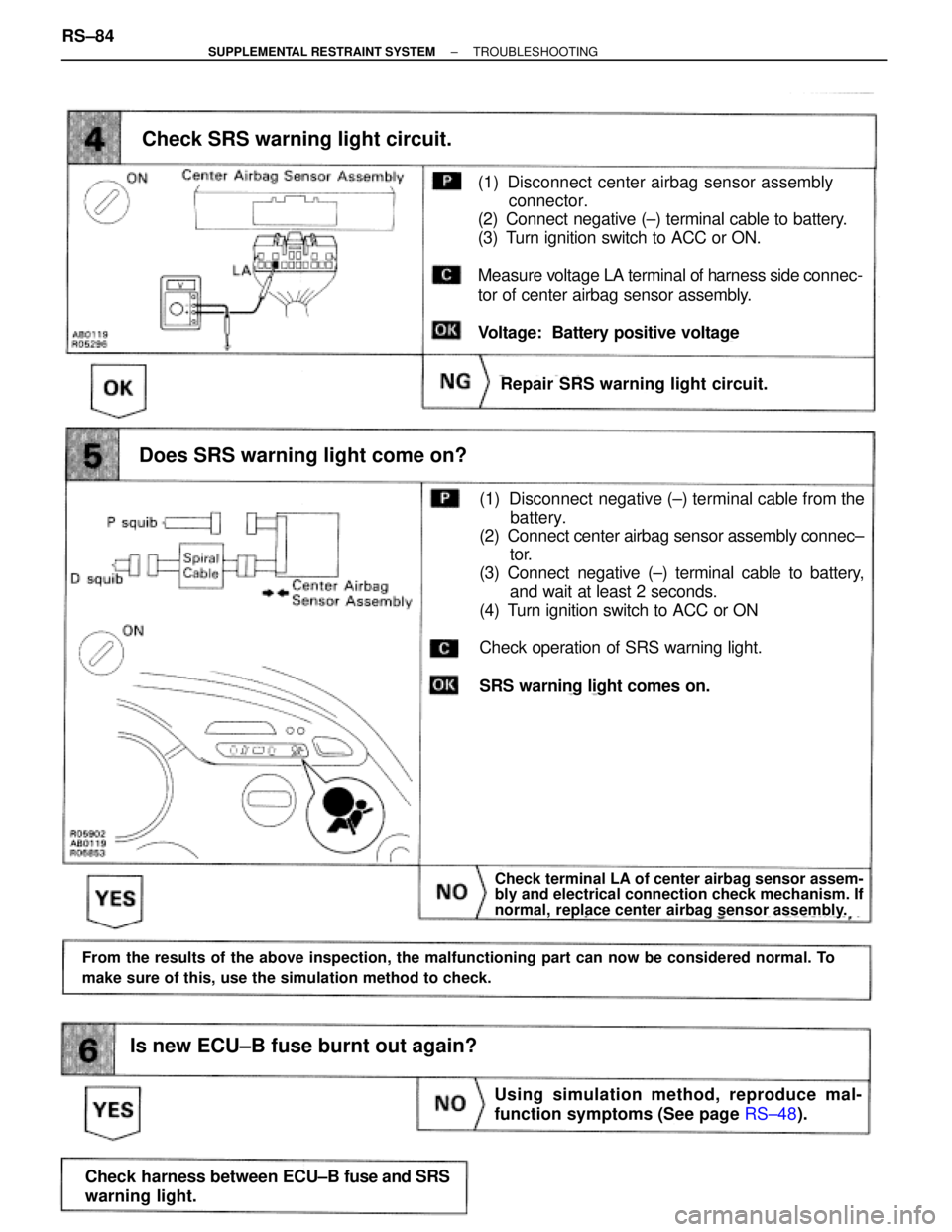
Check SRS warning light circuit.
Repair SRS warning light circuit.
Does SRS warning light come on?
Using simulation method, reproduce mal-
function symptoms (See page RS±48).
Check terminal LA of center airbag sensor assem-
bly and electrical connection check mechanism. If
normal, replace center airbag sensor assembly.
(1) Disconnect center airbag sensor assembly
connector.
(2) Connect negative (±) terminal cable to battery.
(3) Turn ignition switch to ACC or ON.
Measure voltage LA terminal of harness side connec-
tor of center airbag sensor assembly.
Voltage: Battery positive voltage
(1) Disconnect negative (±) terminal cable from the
battery.
(2) Connect center airbag sensor assembly connec±
tor.
(3) Connect negative (±) terminal cable to battery,
and wait at least 2 seconds.
(4) Turn ignition switch to ACC or ON
Check operation of SRS warning light.
SRS warning light comes on.
Check harness between ECU±B fuse and SRS
warning light.
From the results of the above inspection, the malfunctioning part can now be considered normal. To
make sure of this, use the simulation method to check.
Is new ECU±B fuse burnt out again?
RS±84± SUPPLEMENTAL RESTRAINT SYSTEMTROUBLESHOOTING
Page 1768 of 2543
HINT: If diagnostic trouble code 22 is output, do the following troubleshooting:
Is diagnostic trouble code 22 output again?
Repair SRS warning light circuit.
(1) Turn ignition switch to LOCK, and wait at least
2 seconds.
(2) Turn ignition switch to ACC or ON, and wait at
least 20 seconds.
(3) Clear malfunction code stored in memory. (See
page RS±47)
(4) Turn ignition switch to LOCK, and wait at least 20
seconds.
(5) Turn ignition switch to ACC or ON, and wait at
least 20 seconds.
(6) Using SST, connect terminals Tc and E1 of DLC1
or DLC2.
SST 09843±18020
(7) Check diagnostic trouble code.
Replace center airbag sensor assembly.
Using simulation method, reproduce mal-
function symptoms (See page RS±48).
± SUPPLEMENTAL RESTRAINT SYSTEMTROUBLESHOOTINGRS±85
Page 1769 of 2543
DTC 31 Center Airbag Sensor Assembly Malfunction
CIRCUIT DESCRIPTION
The center airbag sensor assembly consists of a center airbag sensor, safing sensor, drive circuit, diagnosis
circuit and ignition control, etc.
It receives signals from the airbag sensors, judges whether or not the SRS must be deployed, and diagnostic
system malfunction.
Diagnostic trouble code 31 is recorded when a occurrence of a malfunction in the center airbag sensor assembly
is detected.
����� �����DTC No.�������������������������������� ��������������������������������Diagnosis����� �
���� �����31
�������������������������������� �
������������������������������� �������������������������������� � Center airbag sensor assembly malfunction.
INSPECTION PROCEDURES
HINT: When a malfunction code other than code 31 is displayed at the same time, first repair the malfunction
indicated by the malfunction code other than code 31.
[P] Preparation [C] Check
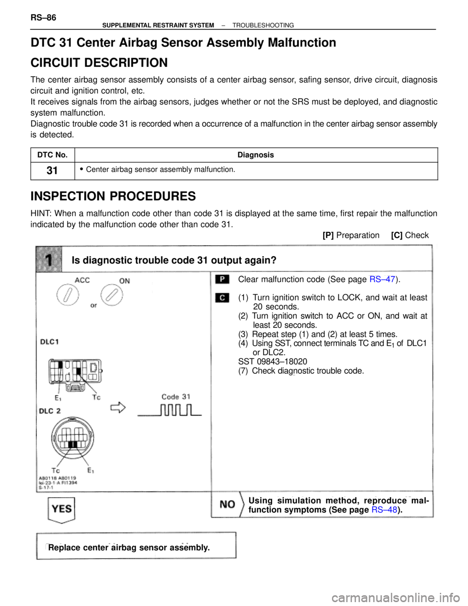
Is diagnostic trouble code 31 output again?
Clear malfunction code (See page RS±47).
(1) Turn ignition switch to LOCK, and wait at least
20 seconds.
(2) Turn ignition switch to ACC or ON, and wait at
least 20 seconds.
(3) Repeat step (1) and (2) at least 5 times.
(4) Using SST, connect terminals TC and E
1 of DL C1
or DLC2.
SST 09843±18020
(7) Check diagnostic trouble code.
Replace center airbag sensor assembly.
Using simulation method, reproduce mal-
function symptoms (See page RS±48). RS±86
± SUPPLEMENTAL RESTRAINT SYSTEMTROUBLESHOOTING
Page 1772 of 2543
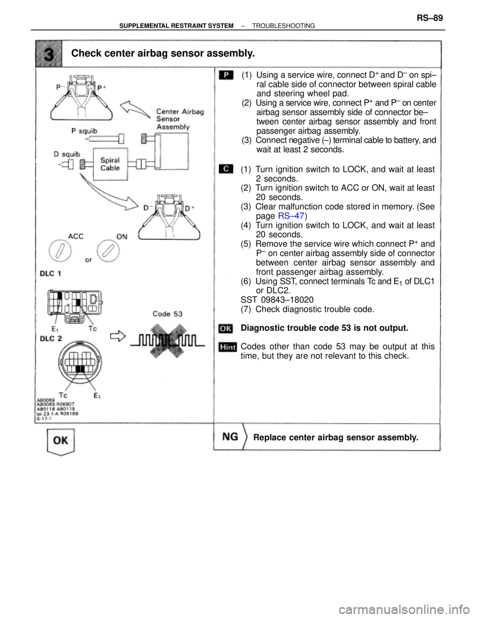
Check center airbag sensor assembly.
(1) Turn ignition switch to LOCK, and wait at least
2 seconds.
(2) Turn ignition switch to ACC or ON, wait at least
20 seconds.
(3) Clear malfunction code stored in memory. (See
page RS±47)
(4) Turn ignition switch to LOCK, and wait at least
20 seconds.
(5) Remove the service wire which connect P
+ and
P± on center airbag assembly side of connector
between center airbag sensor assembly and
front passenger airbag assembly.
(6) Using SST, connect terminals Tc and E
1 of DLC1
or DLC2.
SST 09843±18020
(7) Check diagnostic trouble code.
Diagnostic trouble code 53 is not output.
Codes other than code 53 may be output at this
time, but they are not relevant to this check.
Replace center airbag sensor assembly.
(1) Using a service wire, connect D+
and D± on spi±
ral cable side of connector between spiral cable
and steering wheel pad.
(2) Using a service wire, connect P
+ and P± on center
airbag sensor assembly side of connector be±
tween center airbag sensor assembly and front
passenger airbag assembly.
(3) Connect negative (±) terminal cable to battery, and
wait at least 2 seconds.
± SUPPLEMENTAL RESTRAINT SYSTEMTROUBLESHOOTINGRS±89