Page 870 of 2248
3. REFRIGERANT
Do not put CFC-12 refrigerant into a HFC-134a air condi-
tioning system. Also, do not put HFC-134a refrigerant into
a CFC-12 air conditioning system. If the wrong refrigerant
is used, poor lubrication will result and the compressor
itself may be destroyed.
G4M0979
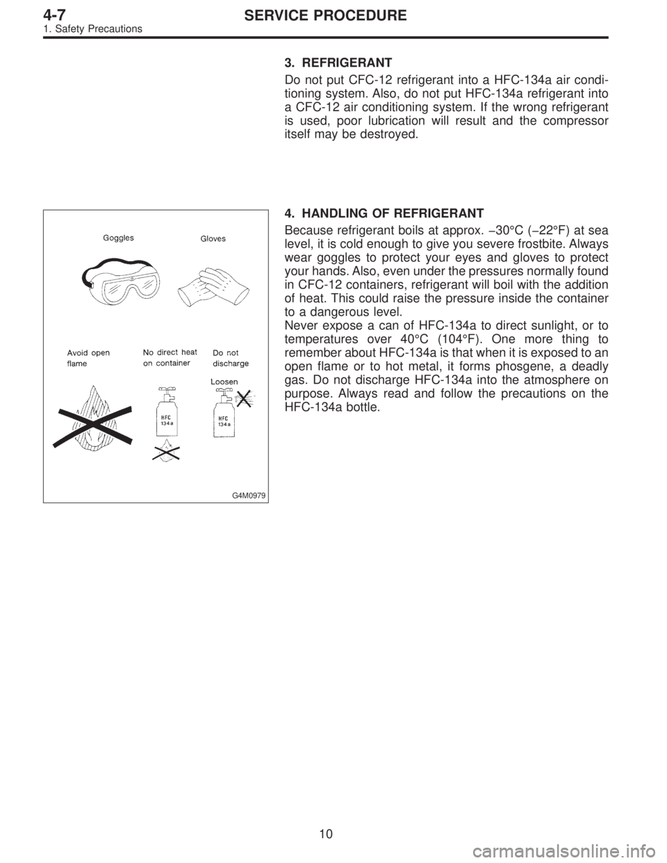
4. HANDLING OF REFRIGERANT
Because refrigerant boils at approx. �30°C (�22°F) at sea
level, it is cold enough to give you severe frostbite. Always
wear goggles to protect your eyes and gloves to protect
your hands. Also, even under the pressures normally found
in CFC-12 containers, refrigerant will boil with the addition
of heat. This could raise the pressure inside the container
to a dangerous level.
Never expose a can of HFC-134a to direct sunlight, or to
temperatures over 40°C (104°F). One more thing to
remember about HFC-134a is that when it is exposed to an
open flame or to hot metal, it forms phosgene, a deadly
gas. Do not discharge HFC-134a into the atmosphere on
purpose. Always read and follow the precautions on the
HFC-134a bottle.
10
4-7SERVICE PROCEDURE
1. Safety Precautions
Page 883 of 2248
8. Leak Testing
The following points should be kept in mind when conduct-
ing a refrigerant leak test.
1) The A/C system to be tested must have an adequate
refrigerant charge to begin with.
2) The area where the leak test is conducted must be free
of wind and drafts, with still air being the ideal condition.
3) The atmosphere where the leak test is conducted must
be free of refrigerant contamination.
4) Operate the A/C system for approx. 10 minutes, then
turn the engine off an begin the leak test.
5) Refrigerant gas is heavier than air, therefore always
hold the probe below the connection being tested.
6) When checking for a leak along a length of hose or
tube, the leak detector probe must be moved slowly,
approx. 25 mm (1 in) per second making sure probe does
not come in contact with the component being tested.
7) When checking for a leak at a certain point, the leak
detector probe must be held at that point for at least 5
seconds.
G4M0609
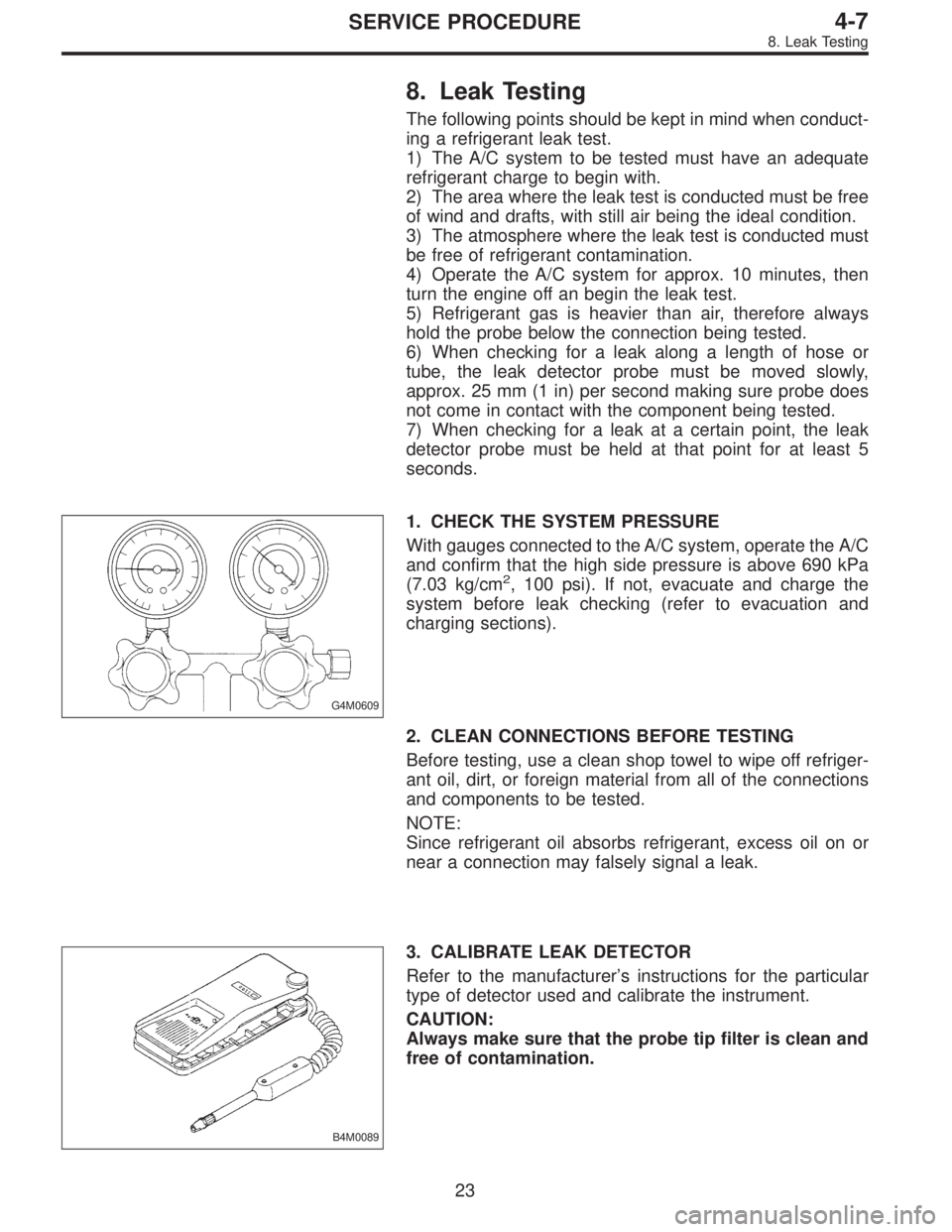
1. CHECK THE SYSTEM PRESSURE
With gauges connected to the A/C system, operate the A/C
and confirm that the high side pressure is above 690 kPa
(7.03 kg/cm
2, 100 psi). If not, evacuate and charge the
system before leak checking (refer to evacuation and
charging sections).
2. CLEAN CONNECTIONS BEFORE TESTING
Before testing, use a clean shop towel to wipe off refriger-
ant oil, dirt, or foreign material from all of the connections
and components to be tested.
NOTE:
Since refrigerant oil absorbs refrigerant, excess oil on or
near a connection may falsely signal a leak.
B4M0089
3. CALIBRATE LEAK DETECTOR
Refer to the manufacturer’s instructions for the particular
type of detector used and calibrate the instrument.
CAUTION:
Always make sure that the probe tip filter is clean and
free of contamination.
23
4-7SERVICE PROCEDURE
8. Leak Testing
Page 889 of 2248
10. Performance Test
1. VEHICLE SET UP
In order to obtain meaningful test results, the vehicle must
be set up to meet the following conditions:
1) Vehicle in shade
2) No wind
3) All vehicle doors closed
4) Front windows opened
5) Hood opened
6) Engine speed set at 1,500 rpm.
7) A/C ON
8) Temperature control lever—Maximum cold
9) Air source—Recirculation
10) Blower speed—4th position (High)
11) Operate A/C for 10 minutes (Minimum) before taking
measurement.
2. MEASUREMENTS
After 10 minutes (Minimum) of A/C operation and using
accurate test equipment, take the following measurements
(in order):
1) Evaporator intake air temperature at recirculation door.
2) Evaporator discharge air temperature at center grill.
3) Condenser (Ambient) intake air temperature measured
0.9 m (3 ft) in front and in line with the center of the con-
denser.
4) Suction (Low) side pressure
5) Discharge (High) side pressure
NOTE:
If only one thermometer is available; 1) take the ambient
measurement first; then 2) the intake air; and 3) dis-
charge air temperature.
29
4-7SERVICE PROCEDURE
10. Performance Test
Page 894 of 2248
2) Connect compressor harness.
3) Connect alternator harness.
4) Install compressor V-belt (Rear).
After adjusting belt tension, tighten tension pulley lock nut
securely.
G4M0632
5) Install alternator V-belt.
After adjusting V-belt tension, tighten alternator bracket
lock bolt securely.
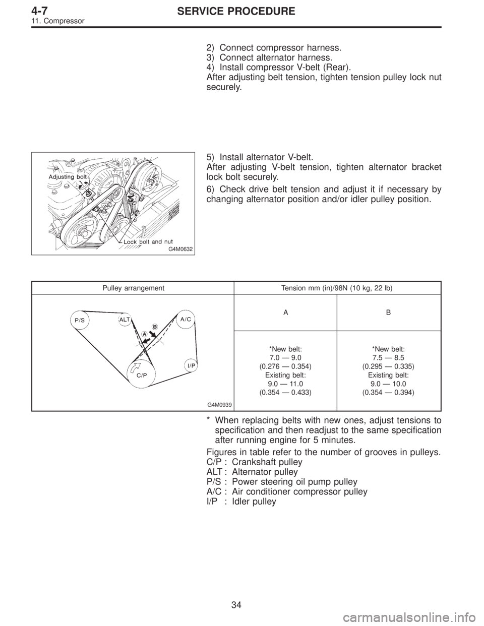
6) Check drive belt tension and adjust it if necessary by
changing alternator position and/or idler pulley position.
Pulley arrangement Tension mm (in)/98N (10 kg, 22 lb)
G4M0939
AB
*New belt:
7.0—9.0
(0.276—0.354)
Existing belt:
9.0—11.0
(0.354—0.433)*New belt:
7.5—8.5
(0.295—0.335)
Existing belt:
9.0—10.0
(0.354—0.394)
* When replacing belts with new ones, adjust tensions to
specification and then readjust to the same specification
after running engine for 5 minutes.
Figures in table refer to the number of grooves in pulleys.
C/P : Crankshaft pulley
ALT : Alternator pulley
P/S : Power steering oil pump pulley
A/C : Air conditioner compressor pulley
I/P : Idler pulley
34
4-7SERVICE PROCEDURE
11. Compressor
Page 905 of 2248
1. Air Conditioning System Diagnosis
43
4-7DIAGNOSTICS
1. Air Conditioning System Diagnosis
Page 906 of 2248
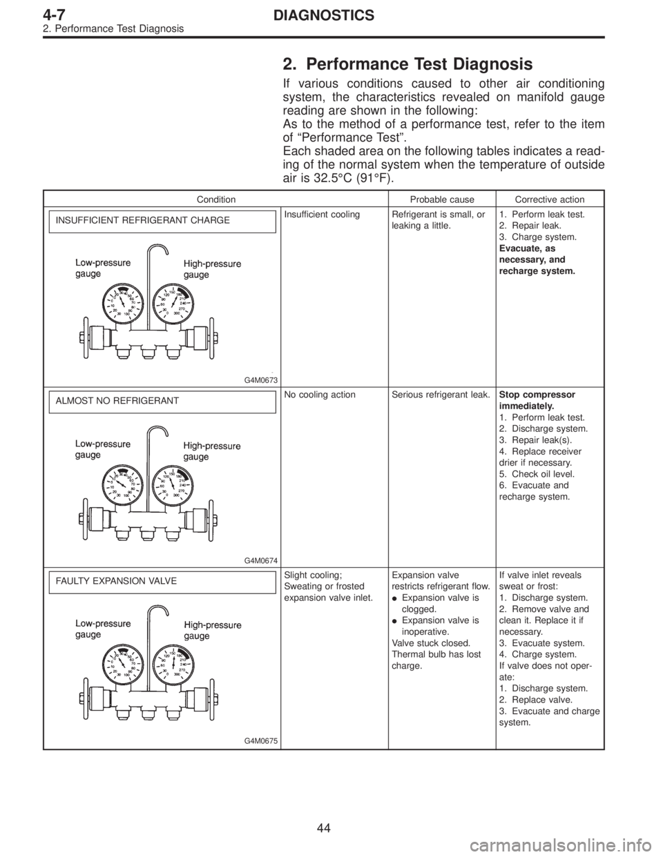
2. Performance Test Diagnosis
If various conditions caused to other air conditioning
system, the characteristics revealed on manifold gauge
reading are shown in the following:
As to the method of a performance test, refer to the item
of“Performance Test”.
Each shaded area on the following tables indicates a read-
ing of the normal system when the temperature of outside
air is 32.5°C (91°F).
Condition Probable cause Corrective action
INSUFFICIENT REFRIGERANT CHARGE
G4M0673
Insufficient cooling Refrigerant is small, or
leaking a little.1. Perform leak test.
2. Repair leak.
3. Charge system.
Evacuate, as
necessary, and
recharge system.
ALMOST NO REFRIGERANT
G4M0674
No cooling action Serious refrigerant leak.Stop compressor
immediately.
1. Perform leak test.
2. Discharge system.
3. Repair leak(s).
4. Replace receiver
drier if necessary.
5. Check oil level.
6. Evacuate and
recharge system.
FAULTY EXPANSION VALVE
G4M0675
Slight cooling;
Sweating or frosted
expansion valve inlet.Expansion valve
restricts refrigerant flow.
�Expansion valve is
clogged.
�Expansion valve is
inoperative.
Valve stuck closed.
Thermal bulb has lost
charge.If valve inlet reveals
sweat or frost:
1. Discharge system.
2. Remove valve and
clean it. Replace it if
necessary.
3. Evacuate system.
4. Charge system.
If valve does not oper-
ate:
1. Discharge system.
2. Replace valve.
3. Evacuate and charge
system.
44
4-7DIAGNOSTICS
2. Performance Test Diagnosis
Page 907 of 2248
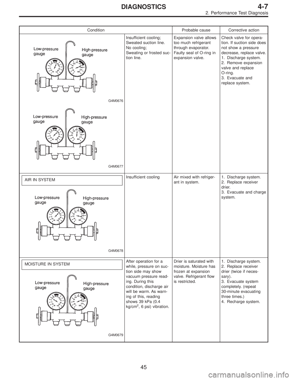
Condition Probable cause Corrective action
G4M0676
G4M0677
Insufficient cooling;
Sweated suction line.
No cooling;
Sweating or frosted suc-
tion line.Expansion valve allows
too much refrigerant
through evaporator.
Faulty seal of O-ring in
expansion valve.Check valve for opera-
tion. If suction side does
not show a pressure
decrease, replace valve.
1. Discharge system.
2. Remove expansion
valve and replace
O-ring.
3. Evacuate and
replace system.
AIR IN SYSTEM
G4M0678
Insufficient cooling Air mixed with refriger-
ant in system.1. Discharge system.
2. Replace receiver
drier.
3. Evacuate and charge
system.
MOISTURE IN SYSTEM
G4M0679
After operation for a
while, pressure on suc-
tion side may show
vacuum pressure read-
ing. During this
condition, discharge air
will be warm. As warn-
ing of this, reading
shows 39 kPa (0.4
kg/cm
2, 6 psi) vibration.Drier is saturated with
moisture. Moisture has
frozen at expansion
valve. Refrigerant flow
is restricted.1. Discharge system.
2. Replace receiver
drier (twice if neces-
sary).
3. Evacuate system
completely. (repeat
30-minute evacuating
three times.)
4. Recharge system.
45
4-7DIAGNOSTICS
2. Performance Test Diagnosis
Page 908 of 2248
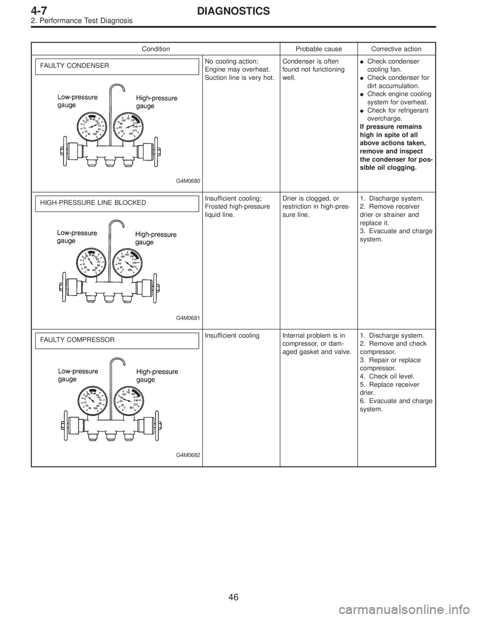
Condition Probable cause Corrective action
FAULTY CONDENSER
G4M0680
No cooling action;
Engine may overheat.
Suction line is very hot.Condenser is often
found not functioning
well.�Check condenser
cooling fan.
�Check condenser for
dirt accumulation.
�Check engine cooling
system for overheat.
�Check for refrigerant
overcharge.
If pressure remains
high in spite of all
above actions taken,
remove and inspect
the condenser for pos-
sible oil clogging.
HIGH-PRESSURE LINE BLOCKED
G4M0681
Insufficient cooling;
Frosted high-pressure
liquid line.Drier is clogged, or
restriction in high-pres-
sure line.1. Discharge system.
2. Remove receiver
drier or strainer and
replace it.
3. Evacuate and charge
system.
FAULTY COMPRESSOR
G4M0682
Insufficient cooling Internal problem is in
compressor, or dam-
aged gasket and valve.1. Discharge system.
2. Remove and check
compressor.
3. Repair or replace
compressor.
4. Check oil level.
5. Replace receiver
drier.
6. Evacuate and charge
system.
46
4-7DIAGNOSTICS
2. Performance Test Diagnosis