Page 117 of 2248
 Approx. 6.1 (6.4, 5.4)
Engine
coolant
pum")
1. Engine Cooling System
A: SPECIFICATIONS
Cooling systemElectric fan + Forced engine coolant circulation
system
Total engine coolant capacity�(US qt, Imp qt) Approx. 6.1 (6.4, 5.4)
Engine
coolant
pumpTypeCentrifugal impeller type
Discharge performance IDischarge 20�(5.3 US gal, 4.4 Imp gal)/min.
Pump speed—total engine cool-
ant head760 rpm — 0.3 mAq (1.0 ftAq)
Engine coolant temperature 85°C (185°F)
Discharge performance IIDischarge 100�(26.4 US gal, 22.0 Imp gal)/min.
Pump speed—total engine cool-
ant head3,000 rpm — 5.0 mAq (16.4 ftAq)
Engine coolant temperature 85°C (185°F)
Discharge performance IIIDischarge 200�(52.8 US gal, 44.0 Imp gal)/min.
Pump speed—total engine cool-
ant head6,000 rpm — 23.0 mAq (75.5 ftAq)
Engine coolant temperature 85°C (185°F)
Impeller diameter 76 mm (2.99 in)
Number of impeller vanes 8
Pump pulley diameter 60 mm (2.36 in)
ThermostatTypeWax pellet type
Starts to open 76 — 80°C (169 — 176°F)
Fully opened91°C (196°F)
Valve lift9.0 mm (0.354 in) or more
Valve bore35 mm (1.38 in)
Radiator fanMotor120 W
Fan diameter x Blade 320 mm (12.60 in) x 5
RadiatorTypeCross flow, pressure type
Core dimensions670x361x16mm
(26.38 x 14.21 x 0.63 in)
Pressure range in which cap valve is openAbove: 88±10 kPa
(0.9±0.1 kg/cm
2, 12.8±1.4 psi)
Below: �4.9 to �9.8 kPa
(�0.05 to �0.1 kg/cm
2, �0.7 to �1.4 psi)
FinsCorrugated fin type
Reservoir
tankCapacity 0.5�(0.5 US qt, 0.4 Imp qt)
B: SERVICE DATA
Engine
coolant
pumpClearance between impeller and caseStandard
Limit0.5 — 0.7 mm (0.020 — 0.028 in)
1.0 mm (0.039 in)
“Thrust” runout of impeller end 0.5 mm (0.020 in)
2
2-5SPECIFICATIONS AND SERVICE DATA
1. Engine Cooling System
Page 119 of 2248
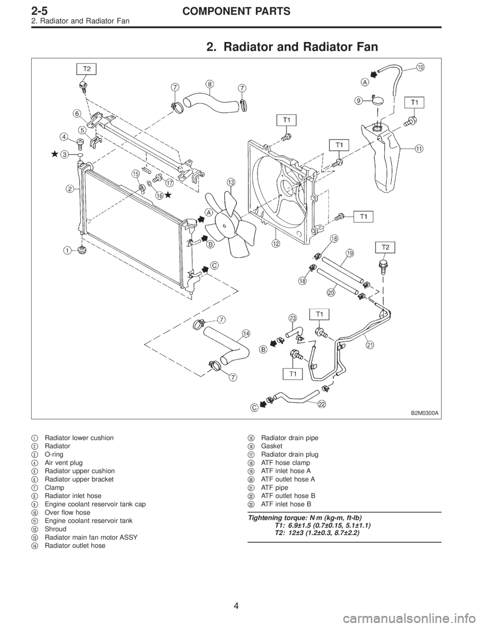
2. Radiator and Radiator Fan
B2M0300A
�1Radiator lower cushion
�
2Radiator
�
3O-ring
�
4Air vent plug
�
5Radiator upper cushion
�
6Radiator upper bracket
�
7Clamp
�
8Radiator inlet hose
�
9Engine coolant reservoir tank cap
�
10Over flow hose
�
11Engine coolant reservoir tank
�
12Shroud
�
13Radiator main fan motor ASSY
�
14Radiator outlet hose�
15Radiator drain pipe
�
16Gasket
�
17Radiator drain plug
�
18ATF hose clamp
�
19ATF inlet hose A
�
20ATF outlet hose A
�
21ATF pipe
�
22ATF outlet hose B
�
23ATF inlet hose B
Tightening torque: N⋅m (kg-m, ft-lb)
T1: 6.9±1.5 (0.7±0.15, 5.1±1.1)
T2: 12±3 (1.2±0.3, 8.7±2.2)
4
2-5COMPONENT PARTS
2. Radiator and Radiator Fan
Page 121 of 2248
1. On-Car Service
A: DRAINING OF ENGINE COOLANT
1) Lift-up the vehicle.
B2M0133A
2) Fit vinyl tube to drain pipe.
B2M0015A
3) Loosen drain cock to drain engine coolant into con-
tainer.
NOTE:
Remove radiator cap so that engine coolant will drain
faster.
B2M0301
B: FILLING OF ENGINE COOLANT
1) Remove air vent plug from radiator.
B2M0135
2) Fill engine coolant into radiator up to filler neck position.
6
2-5SERVICE PROCEDURE
1. On-Car Service
Page 122 of 2248
 Fill engine coolant into reservoir tank up to upper level.
4) Attach radiator cap and reservoir tank cap properly.
5) Install air vent plug.
6) Warm-up engine completely for more than five")
B2M0140
3) Fill engine coolant into reservoir tank up to upper level.
4) Attach radiator cap and reservoir tank cap properly.
5) Install air vent plug.
6) Warm-up engine completely for more than five minutes
at 2,000 to 3,000 rpm.
7) Stop engine and wait until temperature drops to a safe
level.
8) If engine coolant level drops in radiator, add engine
coolant to filler neck position.
9) If engine coolant level drops from upper level of reser-
voir tank, add engine coolant to upper level.
10) Attach radiator cap and reservoir tank cap properly.
B2M0136
C: CHECKING OF COOLING SYSTEM
1) Remove radiator cap, top off radiator, and attach tester
to radiator in place of cap.
2) Apply a pressure of 157 kPa (1.6 kg/cm
2, 23 psi) to
radiator to check if:
(1) Engine coolant leaks at/around radiator.
(2) Engine coolant leaks at/around hoses or connec-
tions.
CAUTION:
�Engine should be off.
�Wipe engine coolant from check points in advance.
�Be careful to prevent engine coolant from spurting
out when removing tester.
�Be careful also not to deform filler neck of radiator
when installing or removing tester.
7
2-5SERVICE PROCEDURE
1. On-Car Service
Page 131 of 2248
G2M0223
5. Radiator Cap
A: INSPECTION
1) Attach radiator cap to tester.
2) Increase pressure until tester gauge pointer stops.
Radiator cap is functioning properly if it holds the service
limit pressure for five to six seconds.
Standard pressure:
78—98 kPa (0.8—1.0 kg/cm
2,11—14 psi)
Service limit pressure:
69 kPa (0.7 kg/cm
2, 10 psi)
CAUTION:
Be sure to remove foreign matter and rust from the cap
in advance; otherwise, results of pressure test will be
incorrect.
G2M0263
6. Radiator Fan and Fan Motor
A: REMOVAL
1) Disconnect ground cable from battery terminal.
2) Disconnect connector of fan motor.
G2M0224
3) Remove reservoir tank.
B2M0308
4) Remove four bolts holding shroud to radiator.
15
2-5SERVICE PROCEDURE
5. Radiator Cap - 6. Radiator Fan and Fan Motor
Page 132 of 2248
G2M0223
5. Radiator Cap
A: INSPECTION
1) Attach radiator cap to tester.
2) Increase pressure until tester gauge pointer stops.
Radiator cap is functioning properly if it holds the service
limit pressure for five to six seconds.
Standard pressure:
78—98 kPa (0.8—1.0 kg/cm
2,11—14 psi)
Service limit pressure:
69 kPa (0.7 kg/cm
2, 10 psi)
CAUTION:
Be sure to remove foreign matter and rust from the cap
in advance; otherwise, results of pressure test will be
incorrect.
G2M0263
6. Radiator Fan and Fan Motor
A: REMOVAL
1) Disconnect ground cable from battery terminal.
2) Disconnect connector of fan motor.
G2M0224
3) Remove reservoir tank.
B2M0308
4) Remove four bolts holding shroud to radiator.
15
2-5SERVICE PROCEDURE
5. Radiator Cap - 6. Radiator Fan and Fan Motor
Page 347 of 2248

Automatic
transmis-
sionOil pumpType Variable-capacity type vane pump
Driving method Driven by engine
Number of vanes 9 pieces
Hydraulic
controlTypeElectronic/hydraulic control
[Four forward speed changes by electrical signals
of car speed and accelerator (throttle) opening]
Fluid Dexron II type Automatic transmission fluid
Fluid capacity 7.9�(8.4 US qt, 7.0 Imp qt)
LubricationLubrication system Forced feed lubrication with oil pump
Oil Automatic transmission fluid (above mentioned.)
Cooling Cooling system Liquid-cooled cooler incorporated in radiator
HarnessInhibitor switch 12 poles
Transmission harness polesFWD ... 11
AWD ... 13
TransferTransfer clutch Hydraulic multi-plate clutch
Control method Electronic, hydraulic type
LubricantThe same Automatic Transmission Fluid used in
automatic transmission.
1st reduction gear ratio 1.000 (53/53)
Final
reductionFinal gear
ratioFront driveFWD 3.900 (39/10)
AWD 4.111 (37/9)
Speedometer gear ratio 0.83 (19/23)
Lubrication oil API, GL-5
Oil
capacityFront drive 1.2�(1.3 US qt, 1.1 Imp qt)
AT F
cooling
systemRadiation capacity 1.651 kW (1,420 kcal/h, 5,635 BTU/h)
3
3-2SPECIFICATIONS AND SERVICE DATA
1. Automatic Transmission and Differential
Page 862 of 2248
4.885 kW
(4,200 kcal/h, 16,666 BTU/h)
RefrigerantHFC-134a (CH
2FCF3)")
1. Air Conditioning System
A: SPECIFICATIONS
Item Specifications
Type of air conditionerReheat air-mix type
Cooling capacity (IMACA)4.885 kW
(4,200 kcal/h, 16,666 BTU/h)
RefrigerantHFC-134a (CH
2FCF3)
[0.6 — 0.7 kg
(1.3 — 1.5 lb)]
CompressorType Swash plate type (DKS-15CH)
Discharge 147 cm
3(8.97 cu in)/rev
Max. permissible speed 7,000 rpm
Magnet clutchTy p eDry, single-disc type
Power consumption 44 W
Type of belt V-Ribbed 4 PK
Pulley dia. (effective dia.) 115 mm (4.53 in)
Pulley ratio1.16
CondenserType Corrugated fin (Multi-flow)
Core face area 0.215 m
2(2.31 sq ft)
Core thickness 19 mm (0.75 in)
Radiation area 4.7 m
2(51 sq ft)
Receiver drier Effective inner capacity 290 cm3(17.70 cu in)
Expansion valve TypeExternal equalizing
EvaporatorTy p eA�-laminate
Dimensions (W x H x T)74 x 224 x 235 mm
(2.91 x 8.82 x 9.25 in)
Blower fanFan typeSirocco fan
Outer diameter x width 150 x 75 mm (5.91 x 2.95 in)
Power consumption 230 W at 12 V
Condenser fan
(Sub fan)Motor typeMagnet
Power consumption 120 W at 12 V
Fan outer diameter 320 mm (12.60 in)
Radiator fan
(Main fan)Motor typeMagnet
Power consumption 120 W at 12 V
Fan outer diameter 320 mm (12.60 in)
Idling speed with
F.I.C.D. in operationMPFI model 850±50 rpm (700±50 rpm “D” range in AT model)
Dual switch
(Pressure switch)
High-pressure line
B4M0083A
Compressor relief valve
blow-out pressure
B4M0084A
Thermo control
amplifier working
temperature
(Evaporator outlet air)
G4M0938
2
4-7SPECIFICATIONS
1. Air Conditioning System
 Lift-up the vehicle.
B2M0133A
2) Fit vinyl tube to drain pipe.
B2M0015A
3) Loosen drain cock to drain engine coolant into con-
tainer.
NOTE:
Remove r")
 Attach radiator cap to tester.
2) Increase pressure until tester gauge pointer stops.
Radiator cap is functioning properly if it holds the service
limit pressu")
 Attach radiator cap to tester.
2) Increase pressure until tester gauge pointer stops.
Radiator cap is functioning properly if it holds the service
limit pressu")