Page 713 of 2248

Whine or growl (continuous or
intermittent)
While engine is running with/
without steering turned.Loosened installation of oil pump,
oil pump bracketRetighten.
*8
Abnormal inside of oil pump, hoseReplace oil pump, hose, if the
noise can be heard when running
as well as stand still.
Torque converter growl
air conditioner compression growlRemove power steering pulley
belt and confirm.
Creaking noise (intermittent)
While engine is running with
steering turned.Abnormal inside of gearboxReplace bad parts of gearbox.
Abnormal bearing for steering
shaftApply grease or replace.
*9
Generates when turning steering
wheel with brake (service or park-
ing) applied.If the noise goes off when brake
is released, it is normal.
*10
Vibration
While engine is running with/
without steering turned.
Too low engine speed at startAdjust and instruct customers.
Vane pump aerationFix wrong part.
Vent air.
Damaged valve in oil pump, gear-
boxReplace oil pump, bad parts of
gearbox.
Looseness of play of steering,
suspension partsRetighten.
*8 Oil pump makes whine or growl noise slightly due to its mechanism. Even if the noise can be heard when steering wheel
is turned at stand still there is no abnormal function in the system provided that the noise eliminates when the vehicle is
running.
*9 When stopping with service brake and/or parking brake applied, power steering can be operated easily due to its light
steering effort. If doing so, the disk rotates slightly and makes creaking noise. The noise is generated by creaking between
the disk and pads. If the noise goes off when the brake is released, there is no abnormal function in the system.
*10 There may be a little vibration around the steering devices when turning steering wheel at standstill, even though the com-
ponent parts are properly adjusted and have no defects.
Hydraulic systems are likely to generate this kind of vibration as well as working noise and fluid noise because of com-
bined conditions, i.e., road surface and tire surface, engine speed and turning speed of steering wheel, fluid temperature
and braking condition.
This phenomena does not indicate there is some abnormal function in the system.
The vibration can be known when steering wheel is turned repeatedly at various speeds from slow to rapid step by step
with parking brake applied on concrete road and in“D”range for automatic transmission vehicle.
97
4-3DIAGNOSTICS
1. Power Steering
Page 735 of 2248
G4M0361
A: ON-CAR SERVICE
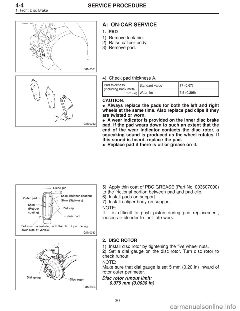
1. PAD
1) Remove lock pin.
2) Raise caliper body.
3) Remove pad.
G4M0362
4) Check pad thickness A.
Pad thickness
(including back metal)
mm (in)Standard value 17 (0.67)
Wear limit 7.5 (0.295)
CAUTION:
�Always replace the pads for both the left and right
wheels at the same time. Also replace pad clips if they
are twisted or worn.
�A wear indicator is provided on the inner disc brake
pad. If the pad wears down to such an extent that the
end of the wear indicator contacts the disc rotor, a
squeaking sound is produced as the wheel rotates. If
this sound is heard, replace the pad.
�Replace pad if there is oil or grease on it.
G4M0363
5) Apply thin coat of PBC GREASE (Part No. 003607000)
to the frictional portion between pad and pad clip.
6) Install pads on support.
7) Install caliper body on support.
NOTE:
If it is difficult to push piston during pad replacement,
loosen air bleeder to facilitate work.
G4M0364
2. DISC ROTOR
1) Install disc rotor by tightening the five wheel nuts.
2) Set a dial gauge on the disc rotor. Turn disc rotor to
check runout.
NOTE:
Make sure that dial gauge is set 5 mm (0.20 in) inward of
rotor outer perimeter.
Disc rotor runout limit:
0.075 mm (0.0030 in)
20
4-4SERVICE PROCEDURE
1. Front Disc Brake
Page 739 of 2248
B4M0074A
G4M0363
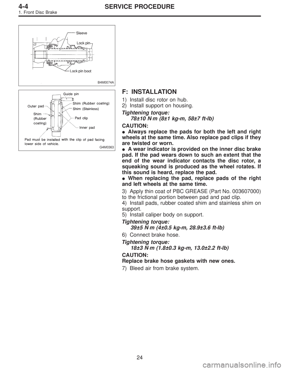
F: INSTALLATION
1) Install disc rotor on hub.
2) Install support on housing.
Tightening torque:
78±10 N⋅m (8±1 kg-m, 58±7 ft-lb)
CAUTION:
�Always replace the pads for both the left and right
wheels at the same time. Also replace pad clips if they
are twisted or worn.
�A wear indicator is provided on the inner disc brake
pad. If the pad wears down to such an extent that the
end of the wear indicator contacts the disc rotor, a
squeaking sound is produced as the wheel rotates. If
this sound is heard, replace the pad.
�When replacing the pad, replace pads of the right
and left wheels at the same time.
3) Apply thin coat of PBC GREASE (Part No. 003607000)
to the frictional portion between pad and pad clip.
4) Install pads, rubber coated shim and stainless shim on
support.
5) Install caliper body on support.
Tightening torque:
39±5 N⋅m (4±0.5 kg-m, 28.9±3.6 ft-lb)
6) Connect brake hose.
Tightening torque:
18±3 N⋅m (1.8±0.3 kg-m, 13.0±2.2 ft-lb)
CAUTION:
Replace brake hose gaskets with new ones.
7) Bleed air from brake system.
24
4-4SERVICE PROCEDURE
1. Front Disc Brake
Page 741 of 2248
G4M0379
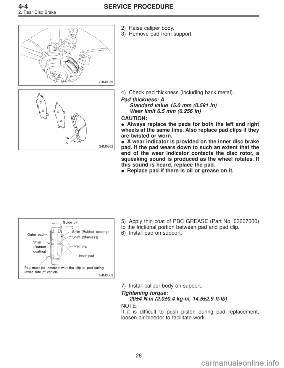
2) Raise caliper body.
3) Remove pad from support.
G4M0362
4) Check pad thickness (including back metal).
Pad thickness: A
Standard value 15.0 mm (0.591 in)
Wear limit 6.5 mm (0.256 in)
CAUTION:
�Always replace the pads for both the left and right
wheels at the same time. Also replace pad clips if they
are twisted or worn.
�A wear indicator is provided on the inner disc brake
pad. If the pad wears down to such an extent that the
end of the wear indicator contacts the disc rotor, a
squeaking sound is produced as the wheel rotates. If
this sound is heard, replace the pad.
�Replace pad if there is oil or grease on it.
G4M0363
5) Apply thin coat of PBC GREASE (Part No. 03607000)
to the frictional portion between pad and pad clip.
6) Install pad on support.
7) Install caliper body on support.
Tightening torque:
20±4 N⋅m (2.0±0.4 kg-m, 14.5±2.9 ft-lb)
NOTE:
If it is difficult to push piston during pad replacement,
loosen air bleeder to facilitate work.
26
4-4SERVICE PROCEDURE
2. Rear Disc Brake
Page 745 of 2248

F: INSTALLATION
1) Install disc rotor on hub.
2) Install support on back plate.
Tightening torque:
52±6 N⋅m (5.3±0.6 kg-m, 38.3±4.3 ft-lb)
CAUTION:
�Always replace the pads for both the left and right
wheels at the same time. Also replace pad clips if they
are twisted or worn.
�A wear indicator is provided on the inner disc brake
pad. If the pad wears down to such an extent that the
end of the wear indicator contacts the disc rotor, a
squeaking sound is produced as the wheel rotates. If
this sound is heard, replace the pad.
�Replace pads if there is oil or grease on them.
3) Apply thin coat of PBC GREASE (Part No. 003607000)
to the frictional portion between pad and pad clip.
G4M0363
4) Install pads on support.
5) Install caliper body on support.
Tightening torque:
20±4 N⋅m (2.0±0.4 kg-m, 14.5±2.9 ft-lb)
6) Connect brake hose.
Tightening torque:
18±3 N⋅m (1.8±0.3 kg-m, 13.0±2.2 ft-lb)
CAUTION:
�The brake hose must be connected without any
twist.
�Replace brake hose gaskets with new ones.
7) Bleed air from brake system.
30
4-4SERVICE PROCEDURE
2. Rear Disc Brake
Page 834 of 2248
G4M0325
G4M0326
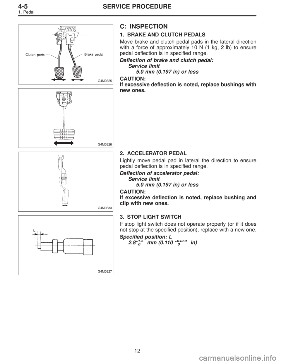
C: INSPECTION
1. BRAKE AND CLUTCH PEDALS
Move brake and clutch pedal pads in the lateral direction
with a force of approximately 10 N (1 kg, 2 lb) to ensure
pedal deflection is in specified range.
Deflection of brake and clutch pedal:
Service limit
5.0 mm (0.197 in) or less
CAUTION:
If excessive deflection is noted, replace bushings with
new ones.
G4M0333
2. ACCELERATOR PEDAL
Lightly move pedal pad in lateral the direction to ensure
pedal deflection is in specified range.
Deflection of accelerator pedal:
Service limit
5.0 mm (0.197 in) or less
CAUTION:
If excessive deflection is noted, replace bushing and
clip with new ones.
G4M0327
3. STOP LIGHT SWITCH
If stop light switch does not operate properly (or if it does
not stop at the specified position), replace with a new one.
Specified position: L
2.8
+1.5
0mm (0.110+0.059
0in)
12
4-5SERVICE PROCEDURE
1. Pedal