Page 346 of 2248

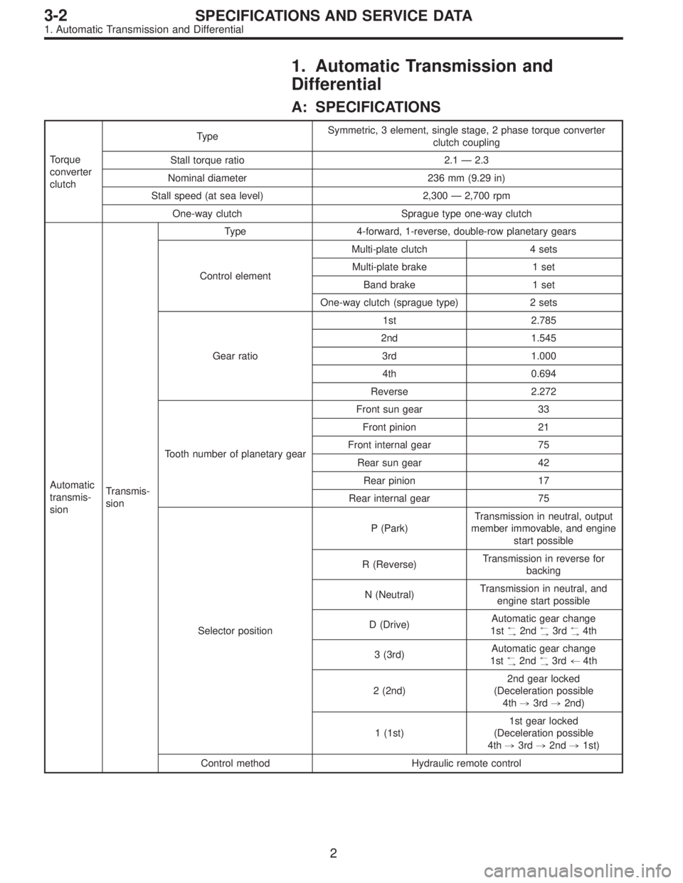
1. Automatic Transmission and
Differential
A: SPECIFICATIONS
Torque
converter
clutchTypeSymmetric, 3 element, single stage, 2 phase torque converter
clutch coupling
Stall torque ratio 2.1 — 2.3
Nominal diameter 236 mm (9.29 in)
Stall speed (at sea level) 2,300 — 2,700 rpm
One-way clutch Sprague type one-way clutch
Automatic
transmis-
sionTransmis-
sionType 4-forward, 1-reverse, double-row planetary gears
Control elementMulti-plate clutch 4 sets
Multi-plate brake 1 set
Band brake 1 set
One-way clutch (sprague type) 2 sets
Gear ratio1st 2.785
2nd 1.545
3rd 1.000
4th 0.694
Reverse 2.272
Tooth number of planetary gearFront sun gear 33
Front pinion 21
Front internal gear 75
Rear sun gear 42
Rear pinion 17
Rear internal gear 75
Selector positionP (Park)Transmission in neutral, output
member immovable, and engine
start possible
R (Reverse)Transmission in reverse for
backing
N (Neutral)Transmission in neutral, and
engine start possible
D (Drive)Automatic gear change
1st
+
,2nd+
,3rd+
,4th
3 (3rd)Automatic gear change
1st
+
,2nd+
,3rd+4th
2 (2nd)2nd gear locked
(Deceleration possible
4th,3rd,2nd)
1 (1st)1st gear locked
(Deceleration possible
4th,3rd,2nd,1st)
Control method Hydraulic remote control
2
3-2SPECIFICATIONS AND SERVICE DATA
1. Automatic Transmission and Differential
Page 969 of 2248
B6M0146
13. Door Mirror
A: REMOVAL
1) Remove the gusset cover.
B5M0296
2) Remove inner remote control switch cover.
B5M0297
3) Remove inner remote control switch.
4) Remove front door trim.
B5M0298A
5) Disconnect the door mirror connector.
6) Remove the door mirror installation screws.
B: INSTALLATION
Installation is in the reverse order of removal.
49
5-1SERVICE PROCEDURE
13. Door Mirror
Page 1144 of 2248
![SUBARU LEGACY 1995 Service Repair Manual B6M0133
B: INSPECTION
1. DOOR LOCK SWITCH (DRIVER’S DOOR)
1) Remove door trim panel. <Ref. to 5-2 [W2A2].>
2) Disconnect connector of door switch.
3) Set switch to each position and check continuity SUBARU LEGACY 1995 Service Repair Manual B6M0133
B: INSPECTION
1. DOOR LOCK SWITCH (DRIVER’S DOOR)
1) Remove door trim panel. <Ref. to 5-2 [W2A2].>
2) Disconnect connector of door switch.
3) Set switch to each position and check continuity](/manual-img/17/57432/w960_57432-1143.png)
B6M0133
B: INSPECTION
1. DOOR LOCK SWITCH (DRIVER’S DOOR)
1) Remove door trim panel.
2) Disconnect connector of door switch.
3) Set switch to each position and check continuity
between terminals as indicated in table below:
Terminal
Switch position12
UNLOCK��
LOCK
B6M0135
2. ACTUATOR
1) Remove door trim panel.
2) Disconnect connector of actuator.
3) Make sure that door link moves to LOCK or UNLOCK
position when battery voltage is applied between terminals
as described below:
�Connect battery positive (+) terminal to terminal No. 2,
and negative (�) terminal to terminal No. 4 at a moment.
�Connect battery positive (+) terminal to terminal No. 4,
and negative terminal (�) to terminal No. 2 at a moment.
B6M0352A
18. Remote Controlled Rearview Mirror
A: REMOVAL AND INSTALLATION
1. REMOTE CONTROLLED REARVIEW MIRROR
SWITCH
1) Remove rearview mirror switch from instrument panel
by using a small standard screwdriver.
CAUTION:
Do not pry rearview mirror switch forcefully as this
may scratch instrument panel.
2) Remove rearview mirror switch while disconnecting
connector.
42
6-2SERVICE PROCEDURE
17. Power Door Lock - 18. Remote Controlled Rearview Mirror
Page 1145 of 2248
![SUBARU LEGACY 1995 Service Repair Manual B6M0133
B: INSPECTION
1. DOOR LOCK SWITCH (DRIVER’S DOOR)
1) Remove door trim panel. <Ref. to 5-2 [W2A2].>
2) Disconnect connector of door switch.
3) Set switch to each position and check continuity SUBARU LEGACY 1995 Service Repair Manual B6M0133
B: INSPECTION
1. DOOR LOCK SWITCH (DRIVER’S DOOR)
1) Remove door trim panel. <Ref. to 5-2 [W2A2].>
2) Disconnect connector of door switch.
3) Set switch to each position and check continuity](/manual-img/17/57432/w960_57432-1144.png)
B6M0133
B: INSPECTION
1. DOOR LOCK SWITCH (DRIVER’S DOOR)
1) Remove door trim panel.
2) Disconnect connector of door switch.
3) Set switch to each position and check continuity
between terminals as indicated in table below:
Terminal
Switch position12
UNLOCK��
LOCK
B6M0135
2. ACTUATOR
1) Remove door trim panel.
2) Disconnect connector of actuator.
3) Make sure that door link moves to LOCK or UNLOCK
position when battery voltage is applied between terminals
as described below:
�Connect battery positive (+) terminal to terminal No. 2,
and negative (�) terminal to terminal No. 4 at a moment.
�Connect battery positive (+) terminal to terminal No. 4,
and negative terminal (�) to terminal No. 2 at a moment.
B6M0352A
18. Remote Controlled Rearview Mirror
A: REMOVAL AND INSTALLATION
1. REMOTE CONTROLLED REARVIEW MIRROR
SWITCH
1) Remove rearview mirror switch from instrument panel
by using a small standard screwdriver.
CAUTION:
Do not pry rearview mirror switch forcefully as this
may scratch instrument panel.
2) Remove rearview mirror switch while disconnecting
connector.
42
6-2SERVICE PROCEDURE
17. Power Door Lock - 18. Remote Controlled Rearview Mirror
Page 1146 of 2248
B6M0137
2. REARVIEW MIRROR
1) Remove door trim panel.
2) Disconnect connector of rearview mirror.
3) Remove screws which secure rearview mirror, and then
remove rearview mirror.
B6M0139A
B: INSPECTION
1. REARVIEW MIRROR SWITCH
Move rearview mirror switch to each position and check
continuity between terminals as indicated in table below:
Switch
position
TerminalMirror switch Left/Right changing switch
OFF Right Left Up Down Left N Right
7�
9�
6�
8�
2����
����
1�
���
��� �
4����
3
B6M0140
2. REARVIEW MIRROR
Check to ensure that rearview mirror moves properly when
battery voltage is applied to terminals as indicated in table
below:
OperationTerminal connection
(+) (�)
UP 3 1
DOWN 1 3
RIGHT 1 2
LEFT 2 1
43
6-2SERVICE PROCEDURE
18. Remote Controlled Rearview Mirror
Page 1185 of 2248

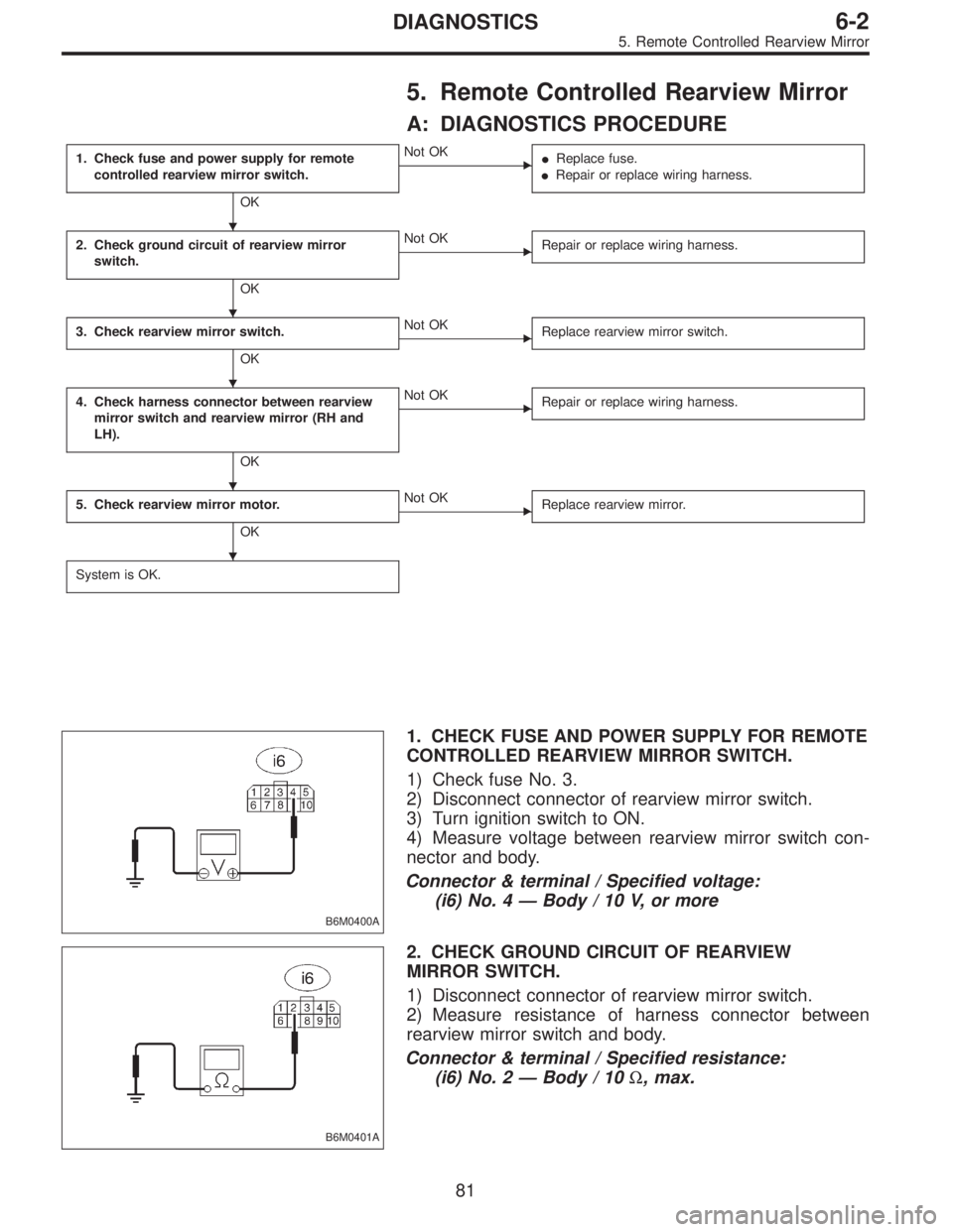
5. Remote Controlled Rearview Mirror
A: DIAGNOSTICS PROCEDURE
1. Check fuse and power supply for remote
controlled rearview mirror switch.
OK
�Not OK
�Replace fuse.
�Repair or replace wiring harness.
2. Check ground circuit of rearview mirror
switch.
OK
�Not OK
Repair or replace wiring harness.
3. Check rearview mirror switch.
OK
�Not OK
Replace rearview mirror switch.
4. Check harness connector between rearview
mirror switch and rearview mirror (RH and
LH).
OK
�Not OK
Repair or replace wiring harness.
5. Check rearview mirror motor.
OK
�Not OK
Replace rearview mirror.
System is OK.
B6M0400A
1. CHECK FUSE AND POWER SUPPLY FOR REMOTE
CONTROLLED REARVIEW MIRROR SWITCH.
1) Check fuse No. 3.
2) Disconnect connector of rearview mirror switch.
3) Turn ignition switch to ON.
4) Measure voltage between rearview mirror switch con-
nector and body.
Connector & terminal / Specified voltage:
(i6) No. 4—Body / 10 V, or more
B6M0401A
2. CHECK GROUND CIRCUIT OF REARVIEW
MIRROR SWITCH.
1) Disconnect connector of rearview mirror switch.
2) Measure resistance of harness connector between
rearview mirror switch and body.
Connector & terminal / Specified resistance:
(i6) No. 2—Body / 10Ω, max.
�
�
�
�
�
81
6-2DIAGNOSTICS
5. Remote Controlled Rearview Mirror
Page 1186 of 2248
![SUBARU LEGACY 1995 Service Repair Manual 3. CHECK REARVIEW MIRROR SWITCH.
Refer to 6-2 [W18B1] for inspection of rearview mirror
switch.
B6M0402A
B6M0469A
4. CHECK HARNESS CONNECTOR BETWEEN
REARVIEW MIRROR SWITCH AND REARVIEW
MIRROR (RH AND SUBARU LEGACY 1995 Service Repair Manual 3. CHECK REARVIEW MIRROR SWITCH.
Refer to 6-2 [W18B1] for inspection of rearview mirror
switch.
B6M0402A
B6M0469A
4. CHECK HARNESS CONNECTOR BETWEEN
REARVIEW MIRROR SWITCH AND REARVIEW
MIRROR (RH AND](/manual-img/17/57432/w960_57432-1185.png)
3. CHECK REARVIEW MIRROR SWITCH.
Refer to 6-2 [W18B1] for inspection of rearview mirror
switch.
B6M0402A
B6M0469A
4. CHECK HARNESS CONNECTOR BETWEEN
REARVIEW MIRROR SWITCH AND REARVIEW
MIRROR (RH AND LH).
1) Disconnect connectors of rearview mirror switch and
rearview mirror.
2) Measure resistance of harness connector between
rearview mirror switch and rearview mirror.
Connector & terminal / Specified resistance:
LHD model:
(i6) No. 1—(D15) No.1/10Ω, max. (RH)
(i6) No. 8—(D15) No.2/10Ω, max. (RH)
(i6) No. 6—(D15) No.3/10Ω, max. (RH)
(i6) No. 1—(D5)No.1/10Ω, max. (LH)
(i6) No. 9—(D5)No.2/10Ω, max. (LH)
(i6) No. 7—(D5)No.3/10Ω, max. (LH)
RHD model:
(i6) No. 1—(D5) No.1/10Ω, max. (RH)
(i6) No. 8—(D5) No.2/10Ω, max. (RH)
(i6) No. 6—(D5) No.3/10Ω, max. (RH)
(i6) No. 1—(D15) No.1/10Ω, max. (LH)
(i6) No. 9—(D15) No.2/10Ω, max. (LH)
(i6) No. 7—(D15) No.3/10Ω, max. (LH)
5. CHECK REARVIEW MIRROR MOTOR.
Refer to 6-2 [W18B2] for inspection of rearview mirror
motor.
82
6-2DIAGNOSTICS
5. Remote Controlled Rearview Mirror
Page 1906 of 2248

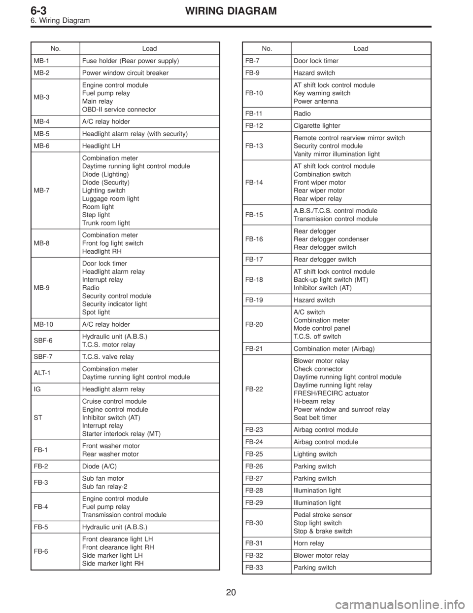
No. Load
MB-1 Fuse holder (Rear power supply)
MB-2 Power window circuit breaker
MB-3Engine control module
Fuel pump relay
Main relay
OBD-II service connector
MB-4 A/C relay holder
MB-5 Headlight alarm relay (with security)
MB-6 Headlight LH
MB-7Combination meter
Daytime running light control module
Diode (Lighting)
Diode (Security)
Lighting switch
Luggage room light
Room light
Step light
Trunk room light
MB-8Combination meter
Front fog light switch
Headlight RH
MB-9Door lock timer
Headlight alarm relay
Interrupt relay
Radio
Security control module
Security indicator light
Spot light
MB-10 A/C relay holder
SBF-6Hydraulic unit (A.B.S.)
T.C.S. motor relay
SBF-7 T.C.S. valve relay
ALT-1Combination meter
Daytime running light control module
IG Headlight alarm relay
STCruise control module
Engine control module
Inhibitor switch (AT)
Interrupt relay
Starter interlock relay (MT)
FB-1Front washer motor
Rear washer motor
FB-2 Diode (A/C)
FB-3Sub fan motor
Sub fan relay-2
FB-4Engine control module
Fuel pump relay
Transmission control module
FB-5 Hydraulic unit (A.B.S.)
FB-6Front clearance light LH
Front clearance light RH
Side marker light LH
Side marker light RHNo. Load
FB-7 Door lock timer
FB-9 Hazard switch
FB-10AT shift lock control module
Key warning switch
Power antenna
FB-11 Radio
FB-12 Cigarette lighter
FB-13Remote control rearview mirror switch
Security control module
Vanity mirror illumination light
FB-14AT shift lock control module
Combination switch
Front wiper motor
Rear wiper motor
Rear wiper relay
FB-15A.B.S./T.C.S. control module
Transmission control module
FB-16Rear defogger
Rear defogger condenser
Rear defogger switch
FB-17 Rear defogger switch
FB-18AT shift lock control module
Back-up light switch (MT)
Inhibitor switch (AT)
FB-19 Hazard switch
FB-20A/C switch
Combination meter
Mode control panel
T.C.S. off switch
FB-21 Combination meter (Airbag)
FB-22Blower motor relay
Check connector
Daytime running light control module
Daytime running light relay
FRESH/RECIRC actuator
Hi-beam relay
Power window and sunroof relay
Seat belt timer
FB-23 Airbag control module
FB-24 Airbag control module
FB-25 Lighting switch
FB-26 Parking switch
FB-27 Parking switch
FB-28 Illumination light
FB-29 Illumination light
FB-30Pedal stroke sensor
Stop light switch
Stop & brake switch
FB-31 Horn relay
FB-32 Blower motor relay
FB-33 Parking switch
20
6-3WIRING DIAGRAM
6. Wiring Diagram